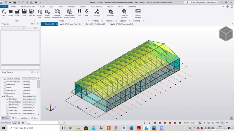
Project 1
Analyze and design a steel building to 10T CRANE as per IS standard code in TEKLA STRUCTURAL DESIGNER. Refer the attached plan and elevation. Provide bracings and moment connection for lateral stability.
Consider dead, live, equipment and wind loading. Consider the brick wall loading for 150mm thick and 1.5 KN per sq m for wall and roof cladding.
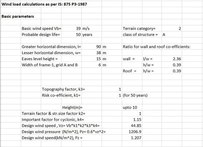
Assume wind loading basic speed as 39m/s
Report of each member to be generated and extract drawings of structural plans from the software
AIM : To analyze and design a steel building to 10T CRANE as per IS standard code in TSD.
TOOLS USED : New, Construction levels, Grids, Parllel(quick), Manage propertysets, beam, column,X brace, wall panel, slab on beams, roof panel , frame, Copy, Load case, Full UDL, Area load, Slab load, Settings, Seismic wizard, Analyze, Property window, Structure window, Status window, Validate.
PROCEDURE :
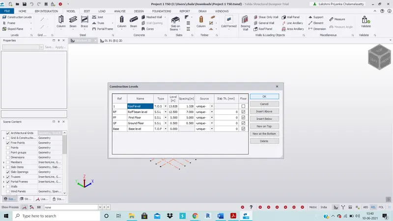
1. Open a new file in the TSD and create levels as per the crossectional view provided.
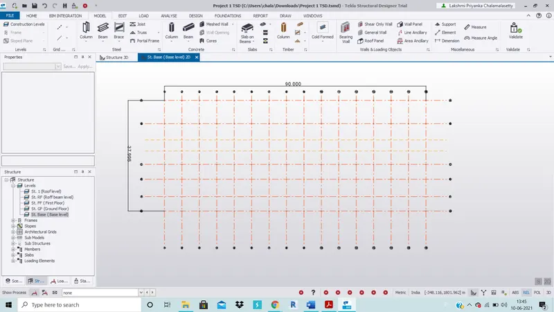
2. Click on base level in the structure window , and draw grids by clicking on Grid tool and Parallel(quick) tool in the Model tab refeering the plan views in the attachment provided.
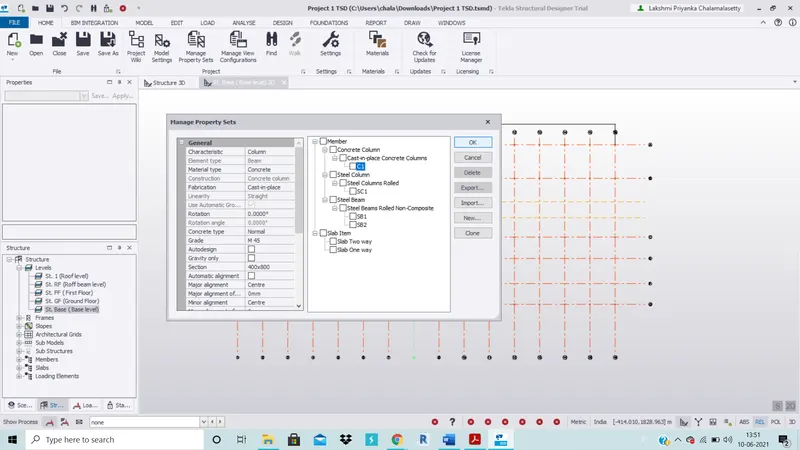
3. Now, click on Manage property sets in the Home tab and create Concrete column, steel column and steel beams as required. Also create slabs. Deselect the Autodesign option, Set the Grade as ISMB and select the appropraite section for the members. Also check the releases of beams and columns. Set the major alignment as bottom and minor as centre. Then click ok.
4. Now, click on column in model tab and select the concrete column in the dropdown in property window and select the points wherver columns are required as per the attachment plan. Set the top constraint as ground floor level.
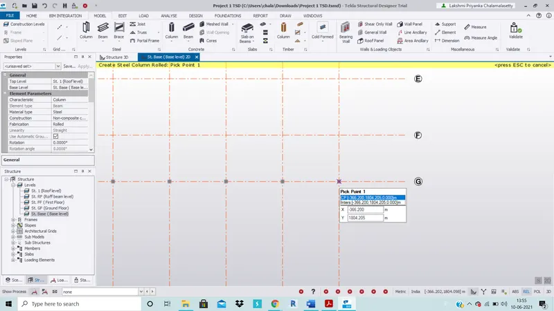
5. Check the concrete columns created in the structure 3D view.
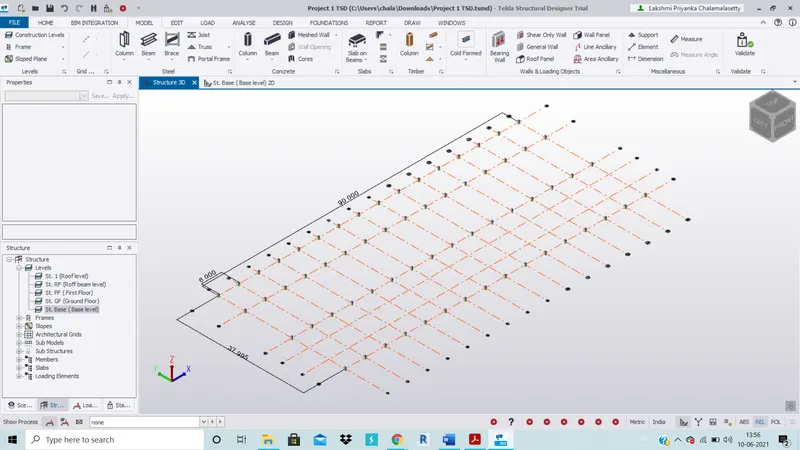
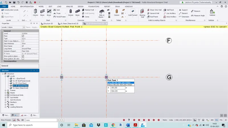
6. Now in the ground floor level, again click on column in model and choose steel column and set the constraints as from ground floor level to roof beam level.
7. Check the steel beams as well in the Structure 3D view.
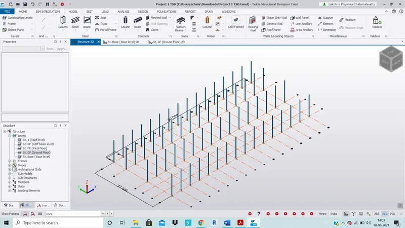
8. Now, click on beams in the model tab and select the steel beam that is created and draw beams between the columns as per the plan attachment.Similarly, draw beams in all the floors.
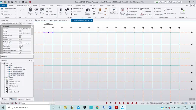
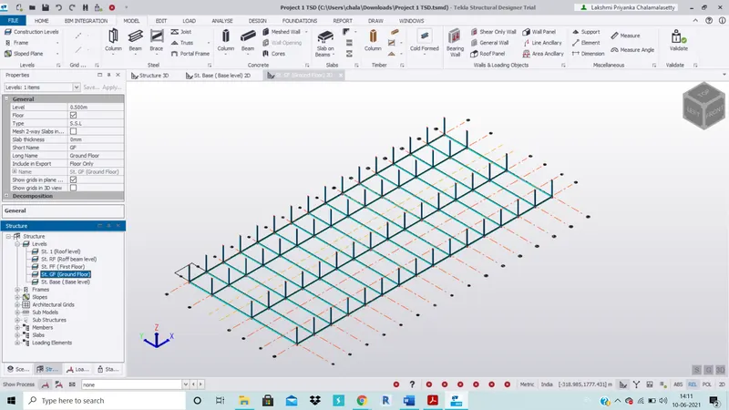
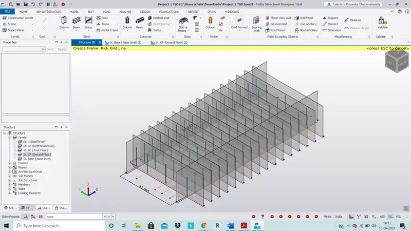
10. Now in the structure 3D view, click on Frame tool in the model tab and create frames for the grid lines.
11. Open the frame in which the grids A, B, C, D, E , F and G are visbile as the crossectional view given has these grids shown. ( Frame 1 is opened ). Draw the construction lines as per the crossection of the attachement and draw steel beams to create roof of the structure.
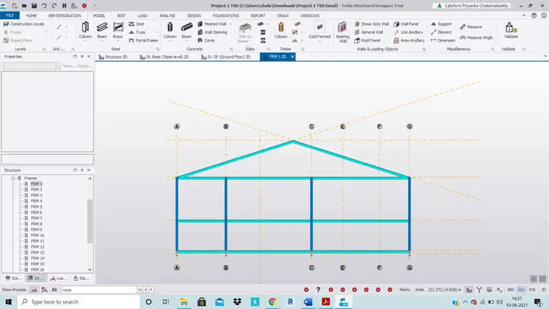
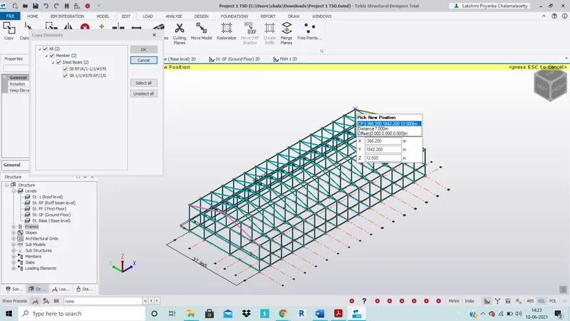
12. Now, in the 3D view copy and paste the roof to all points i.e., point 2,3,4,5,6,7,8,9,10,11,12,13,14,15 and 16. And also join the top points of intersection using a steel beam to create rafter.
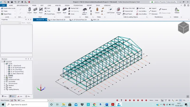
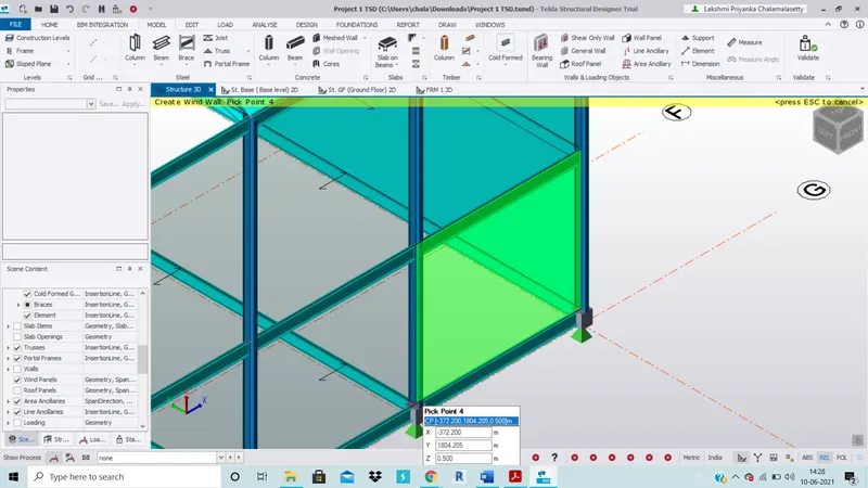
13. Now, click on wall panel in model tab and create panels for all the walls by slecting all 4 points of each panel.
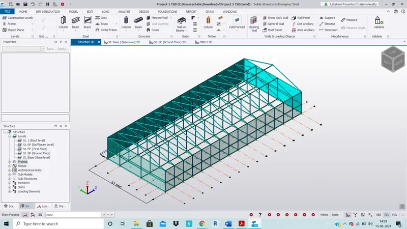
14. Now, click on roof panel in the model tab and create roof panels for the roof of structure.
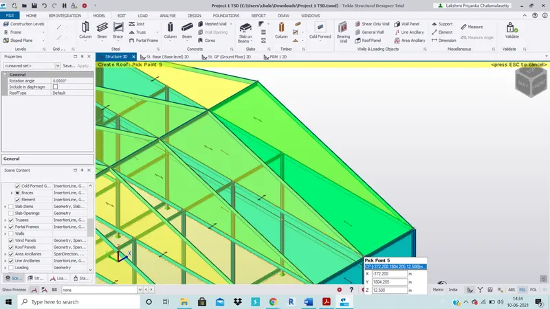
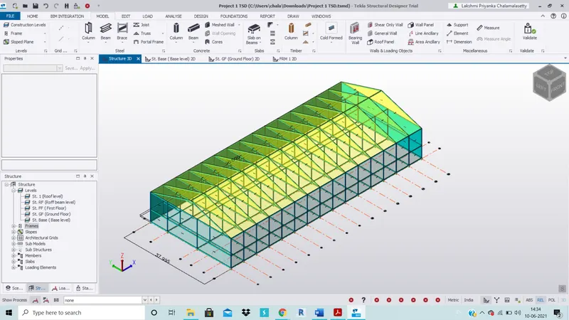
15. Click on brace tool and select X brace and create braces by slecting 4 points on panels and click enter.
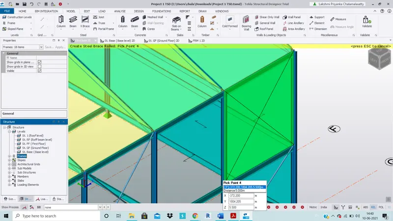
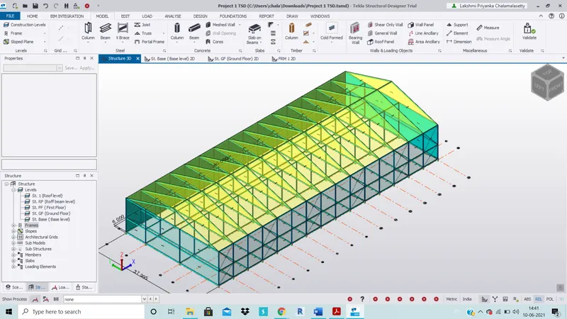
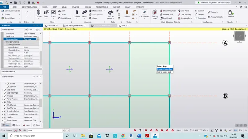
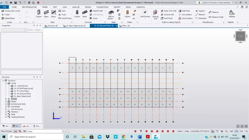
16. Click on slab on beams tool and select 1 way or 2 way slab according to the dimensions and select the bay to create slabs. similarly create for all floors.
17. Click on load cases in the load tab and select Dead load and click on slab load and enter the value of load as 15 KN/m for ground floor beams and 21KN/m for first floor beams as per the calculation performed.
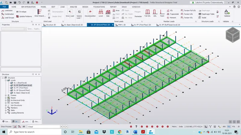
18. NOw, as per the IS 875 code, apply live load by selecting the area load and slecting live load in the load case and entering the values asper the plan .
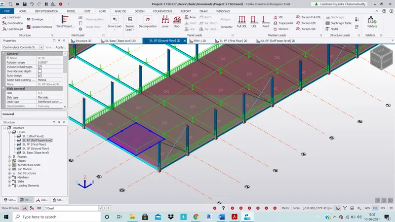
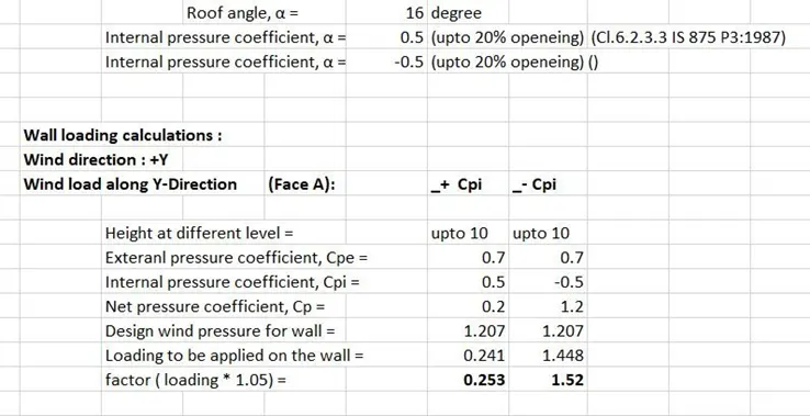
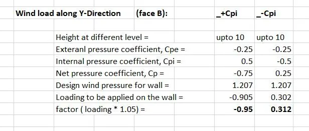
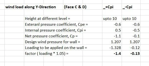
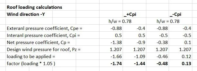
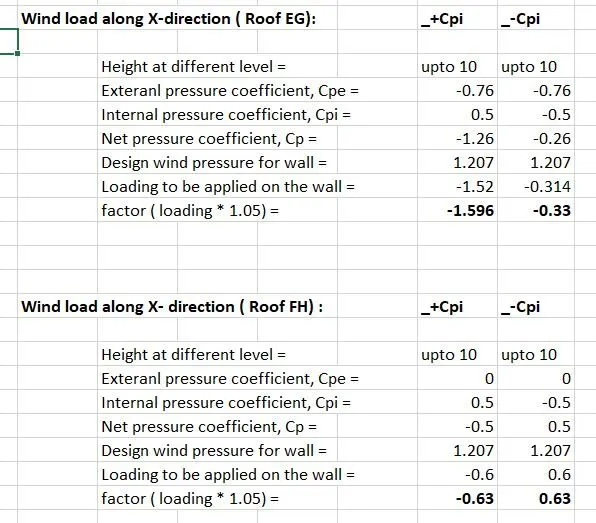
19. now, create a load case named crane load and apply to the plan as line load in the roof beam level. also create wind loads and apply as per the calculated values.
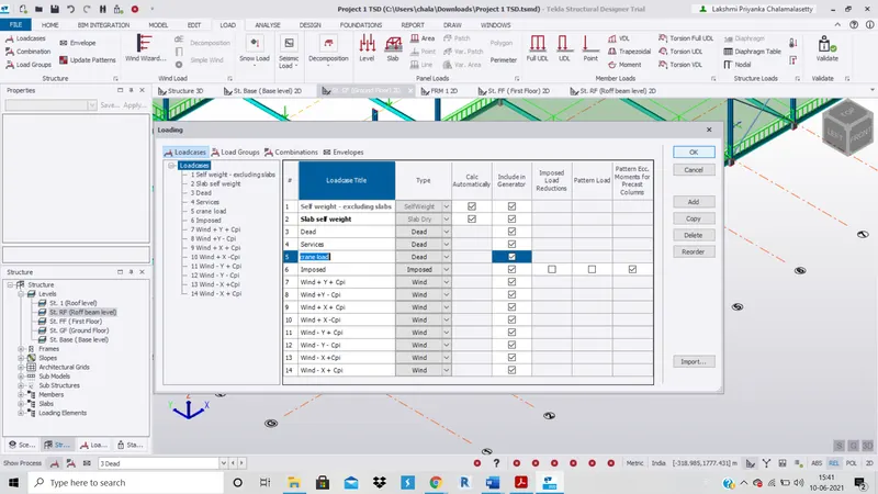
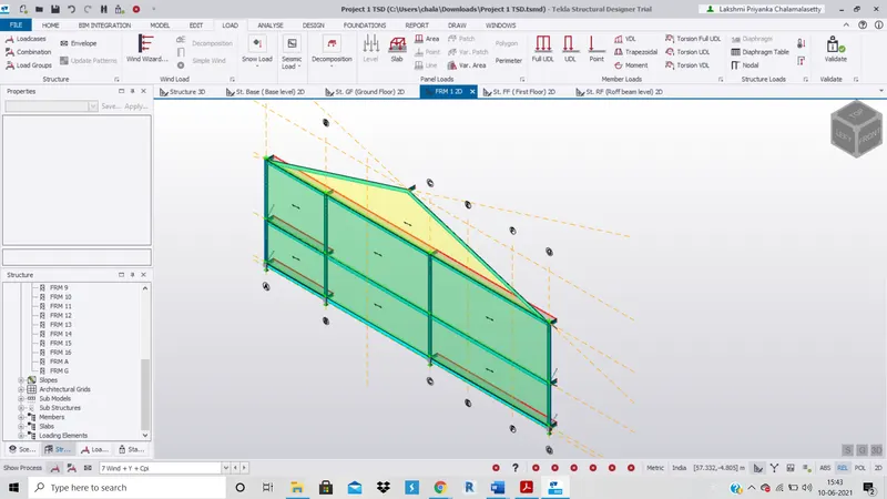
20. Now, click on seismic wizard in seismic load dropdown in the load tab.
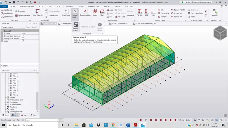
21. And follow the following steps in pictures to craete effective seisemic loading.
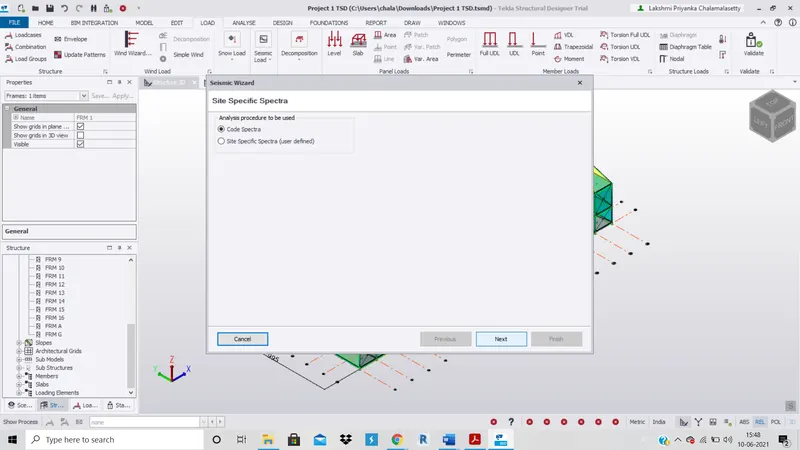
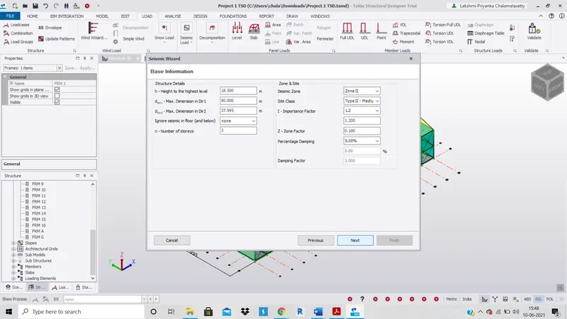
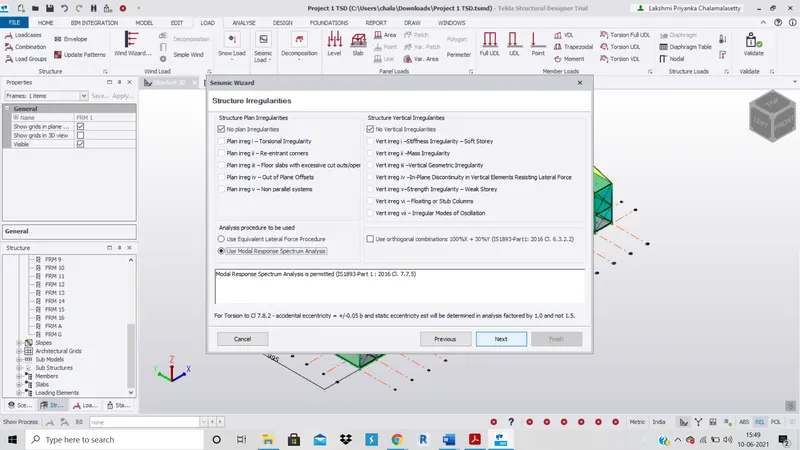
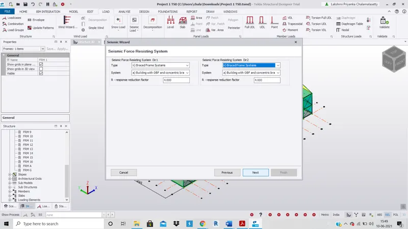
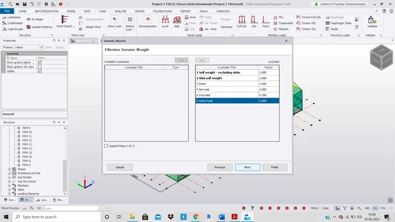
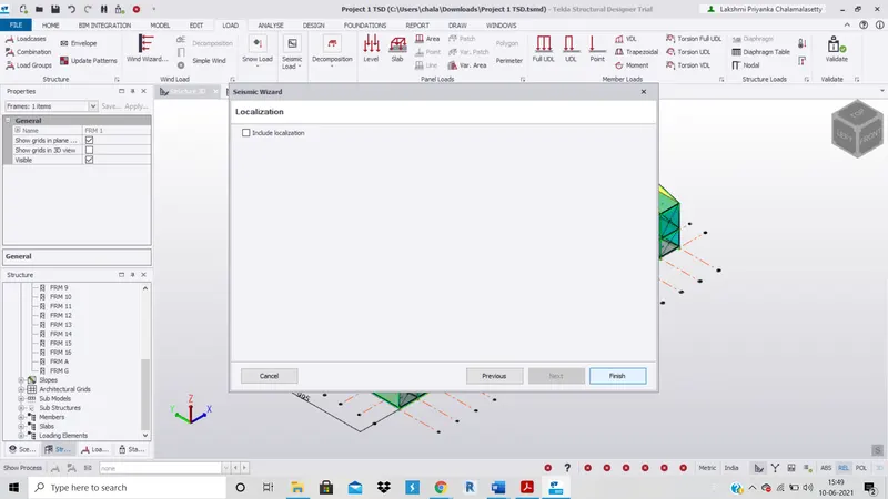
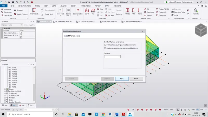
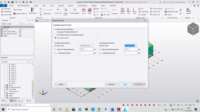
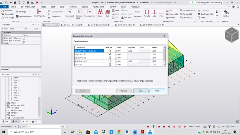
22. Now, click on analysis and check the analysis settings if modular ratios are 1 or not. if not set them to 1 and click ok.
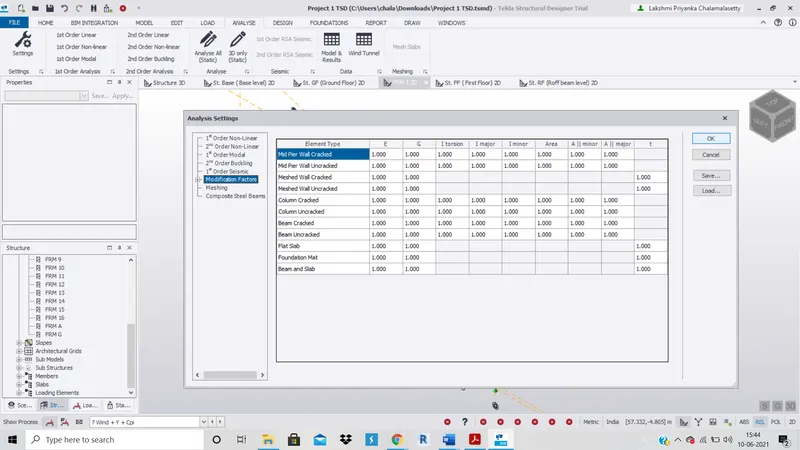
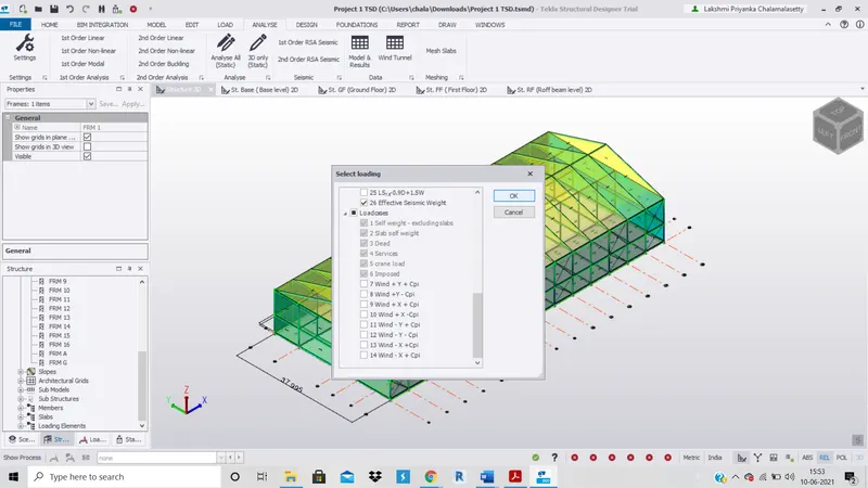
23. Now, click on 1st order linear in the 1st order analysis and click on effective seismic load and click ok.
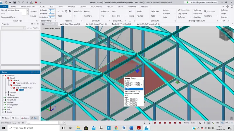
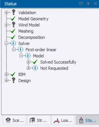
24. Check if there are any errors in the status window and solve them accordingly. I got slab size error so i have solved it by assigning the slab size as 100mm.
25. Again perform the analysis and check if there exixts anymore eroors. ( No errors were shown in my case).
LOAD CALCULATIONS :
DEAD LOAD :
Slab load = (model slab in software)
Finishes loading ( 50 mm thickness ) = 0.05m x 24 KN/m^2.
= 1.2 KN/m^2. (AREA LOADING)
Brickwall with cement plaster thickess = 150 mm .
Unit weight = 20 KN/m^3. (IS:857 Part1 ; Table 1)
Floor height (Ground floor to First floor) = 5.0m
Brick wall loading = (150 x 20 x 5.0)/1000 = 15 KN/m.
Floor height (First floor to Roof beam level) = 7.0m
Brick wall loading = (150 x 20 x 7.0)/1000 = 21 KN/m.
Ceiling loading = 0.3 KN/m.
Roof Loading = 1.5 KN/m.
LIVE LOAD : To be taken from IS 875 code.
Store room = 5 KN/m^2
Office = 3 KN/m^2
Rest room = 2 KN/m^2
Toilets = 2 KN/m^2
Pantry = 3 KN/m^2
Corridor = 4 KN/m^2
Meeting Room = 2KN\m^2
Maintainance Rom = 2.5KN\m
Equipment room = 10 KN/m^2
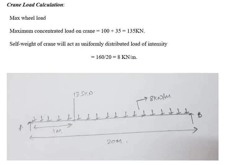
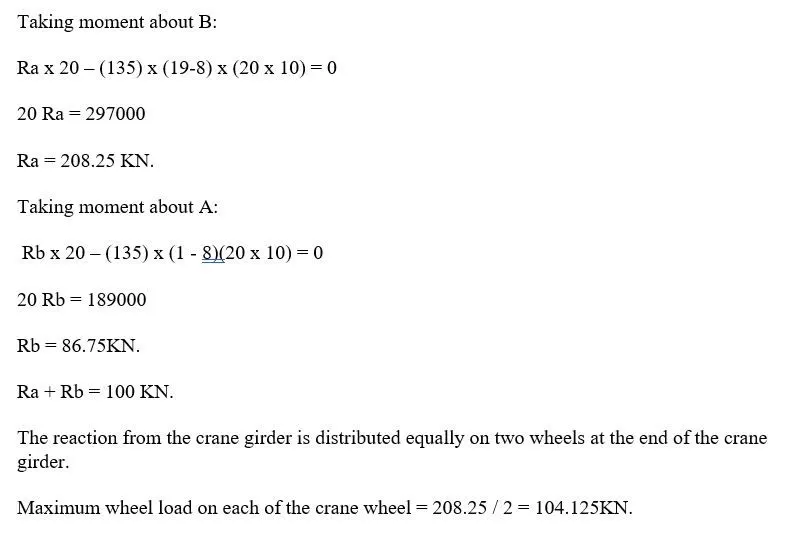
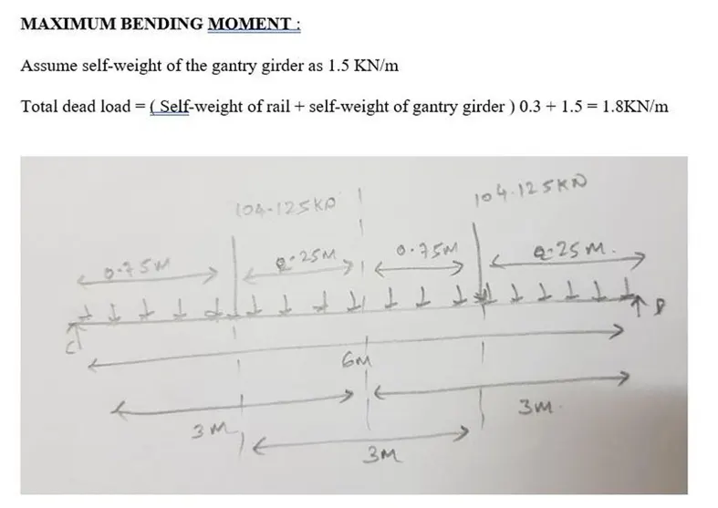
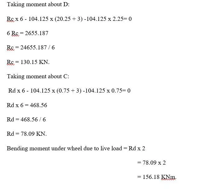
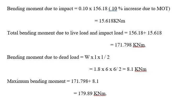
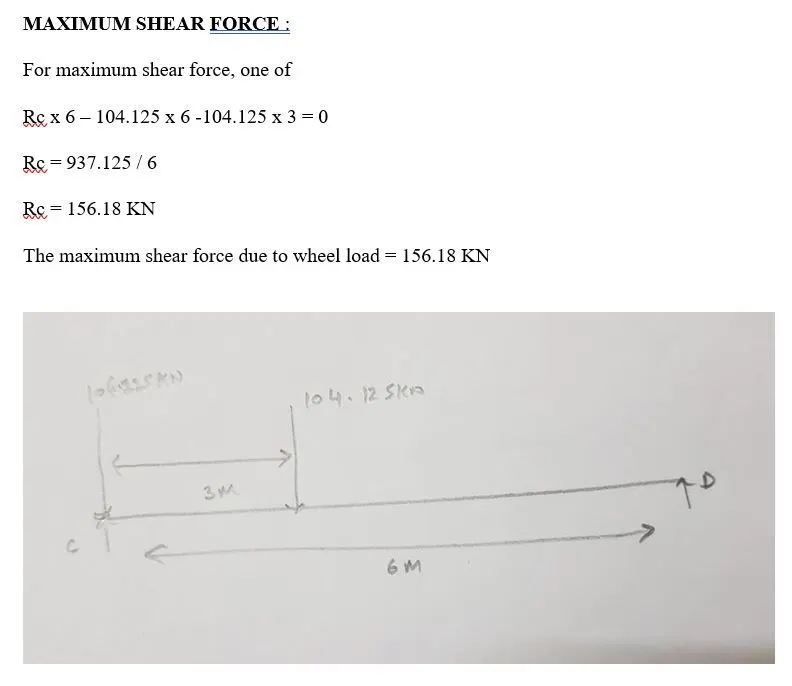
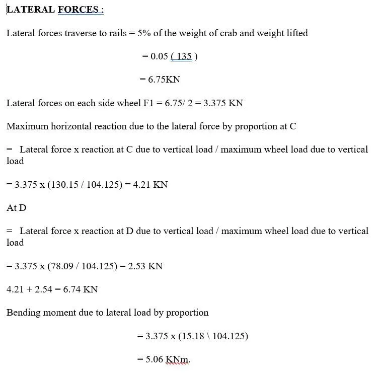
CRANE LOAD :
WIND LOAD :
RESULTS : Steel building was designed and analysed and were to be error free.
STRUCTURE :