Project 1
1. Design a battery pack for a car of roughly 150 kW with 120 V. Use 3500 mAh 3.6V nominal NMC chemistry cell.
a. Design the battery pack configuration.
b. Draw the BMS topology for this battery pack.
Theory :-
A battery pack, or battery pack, is an assembly of battery cells that has been electrically organised into a row by column matrix configuration. This matrix configuration enables the delivery of a targeted range of voltage and current for a period of time against anticipated load scenarios. This technology is known as a battery management system (BMS).
A BMS often offers the following oversight:-
looking after the battery
protecting the batteries
determining a battery's operating status estimate
enhancing battery performance continuously
updating external devices on operational status
Although the word "battery" in this context refers to the whole pack, the monitoring and control features are particularly used to refer to individual cells or collections of cells known as modules in the overall battery pack assembly. With the maximum energy density, lithium-ion rechargeable cells are the go-to option for battery packs in a wide range of consumer goods, from laptops to electric automobiles. Even while they work very well, they may be rather harsh if used outside of a relatively small safe operating area (SOA), with results that can range from impairing battery performance to seriously harmful outcomes. The job description for the BMS is undoubtedly difficult, and both its general complexity and its scope of supervision may touch on a variety of disciplines, including electrical, digital, control, thermal, and hydraulic.
There is no set of requirements that must be followed in order for battery management systems to function. The extent of the technological design and the features actually used often connect with:
the battery pack's price, complexity, and size
Use of the battery and any safety, durability, and warranty issues
Certification requirements from different government legislation where there are severe financial consequences for failing to implement acceptable functional safety measures.
Battery pack protection management and capacity management are two crucial BMS design elements among many others. Here, we'll go through how these two features function. Electrical protection, which means preventing the battery from being harmed by use outside of its SOA, and thermal protection, which entails passive and/or active temperature regulation to keep or bring the pack within its SOA, are the two fundamental facets of battery pack protection management.
Solution :-
Given data:-
Power Needed = 150 KW
Required Voltage = 120 V.
Specs on the battery:
Capacity of battery = 3500 mAh = 3.5 Ah
Battery Nominal Voltage =3.6V
First, use the following steps to find the two parameters:
I Number of cells linked together in a line
ii) The number of parallel connections.
Number of cells linked together in a row
Cells hooked up in series = Required voltage / Nominal cell voltage
=120/3.6=33.33.
Nominal battery voltage =no.of cells in series *cell nominal voltage
= 34*3.6=122.4
So, more voltage is always better.
Number of cells in a row: 34
How many cells are linked together in parallel:
Current =Power/Voltage
=150*1000/120
=1250A
Capacity of battery = 3500 mAh = 3.5 Ah
Battery Nominal Voltage =3.6V
No. of parallel cell=motor continuous current/cell nominal capacity
=1250/3.6
358 cells are next to each other.
∴ The type of battery pack is 34S358P.
BMS topology for this battery pack:
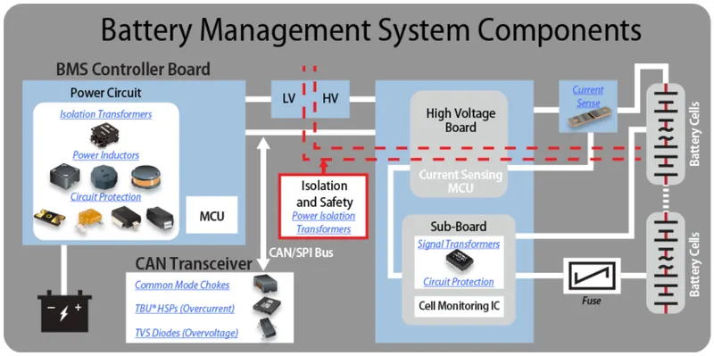
Based on these cells connected in series and the Architecture of BMS we Choose the Master and Slave topology of BMS for this Ev battery pack Topology design.
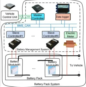
A modular BMS is a mix of the two topologies listed above. This set-up is also called the master and slaves topology or the star topology. There are several control units (slaves) that are all linked together. Each slave is in charge of a group of cells in a battery. The slaves are linked to the master, which is the main control unit. The master is in charge of keeping the whole battery safe and making sure it works right. A modular BMS topology can help find a good balance between price and complexity of design.
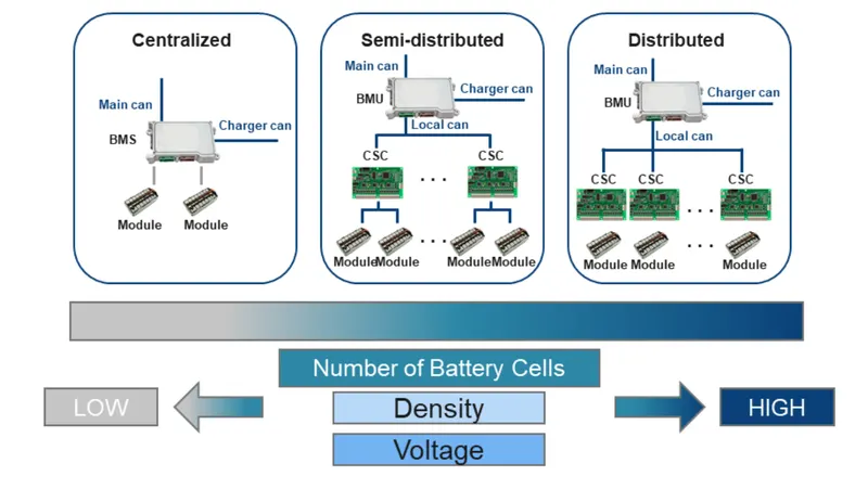
A better variant of a modular BMS is a master-slave BMS. This system resembles a modular one.
We divide the modules into the various master-slave functions and get rid of the ones that the slave modules don't require.
Advantages:-
Save a lot of money.
The primary BMS is in charge of a sizable number of tasks, such as computation, prediction, decision-making, and communication.
Essentially, the slave unit is simply in charge of measuring.
In this sense, it may be considered to inherit the majority of the benefits of a modular construction while also lowering expansion costs.
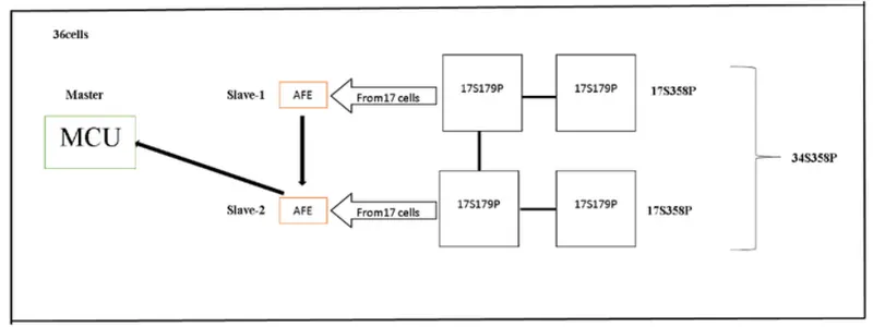
by looking at the above graph
slave 1 gets the information from the 17 cells that are connected to it and sends it to slave 2.
The slave 2 reads the information from 17 cells connected to it and from the slave 1 and sends the information to the master.
The master reads the information from slave 2, which includes both slave 2 and slave 1 information.
So, the master runs the battery pack by getting information.
2. Building a 3S2P battery pack configuration with a generic battery block using Matlab/Simulink:-
Procedure:-
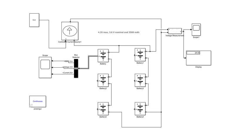
Matlab/Simulink batteries set up in a 3S2P configuration. That means you should connect 3 cells in a row and 2 cells in a parallel line.
So, the total number of cells in the battery pack is 3 x 2 = 6.
It's a 3s2p connection, where the negative end of one battery is connected to the positive end of another battery in series.
Blocks used:-
1. Battery: The Battery block implements a generic dynamic model that represents most popular types of rechargeable batteries.
from this battery model, we will get 3 output value
1. SoC%
2. Current &
3. Voltage
2.Voltage Measurement Block: Used to measure the battery pack's voltage.
3. Controlled current source: We need a controlled current source to drain the battery.
Model Explanation:-
To measure the voltage of the battery pack, the voltage measurement block is connected across the pack. The battery pack's SOC (State of Charge), current, and voltage are shown on the scope's output. The load on the battery pack is the controlled current signal. The capacity of the battery is used to figure out what the constant block is, and it is then given to the controlled current block.
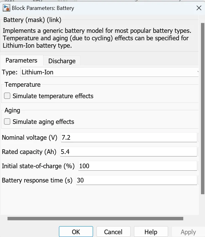
Here are the parameters given inside the battery:
A cell's normal voltage is 7.2V.
5.4Ah is how much a cell can hold.
The most voltage a cell can have is 8.3V.
Nominal voltage of the battery pack = number of cells in series * nominal voltage of a cell = 3 * 7.2v
= 21.6 V
Rated capacity of the battery pack = number of cells in parallel * rated capacity of a cell = 2 * 5.4Ah
= 10.8Ah
This battery pack has a 10.8Ah battery capacity and 21.6V.
The total voltage of the battery pack is the maximum voltage of the battery multiplied by the number of cells connected in series.
= 24.9 v
Overall voltage = 25 V.
Result:-
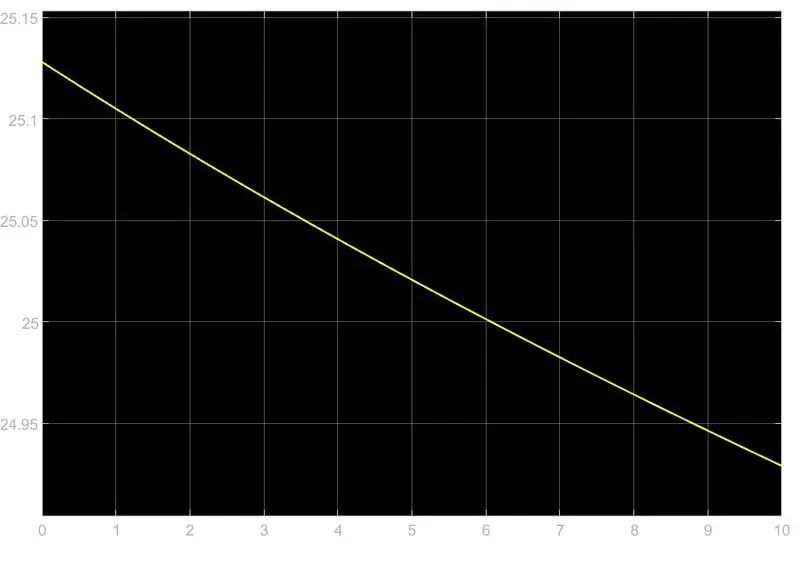
From the above graph, it's clear that when we put a load of 5.4, voltage and soc went down.
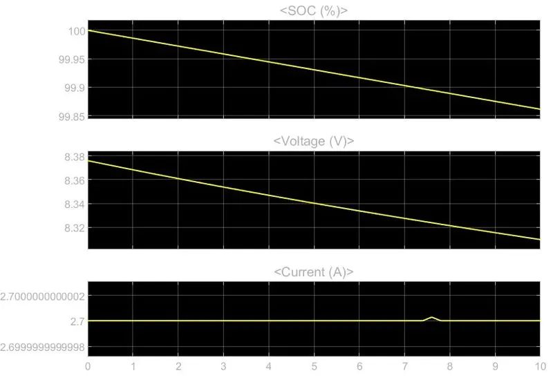
From the above plot, we can see that the total voltage of the battery pack has dropped by 10% of what it was at first.
Conclusion:-
With the help of Simulink, we were able to see the SOC voltage and current of the 3s2p battery pack configuration.
Reference:-
https://www.kemet.com/en/us/technical-resources/bms-and-kemet-metcom-inductors.html
https://www.dnkpower.com/li-ion-bms/
Khalid, A., et al. (2020). Simulation-Based Analysis of Equalization Algorithms on Active Balancing Battery Topologies for Electric Vehicles, Cham, Springer International Publishing.