Project 1
ENGINE HARNESS ROTING
AIM:
- To route the wiring harness on given Engine and flatten view drawing in CATIA V5.
Given data:
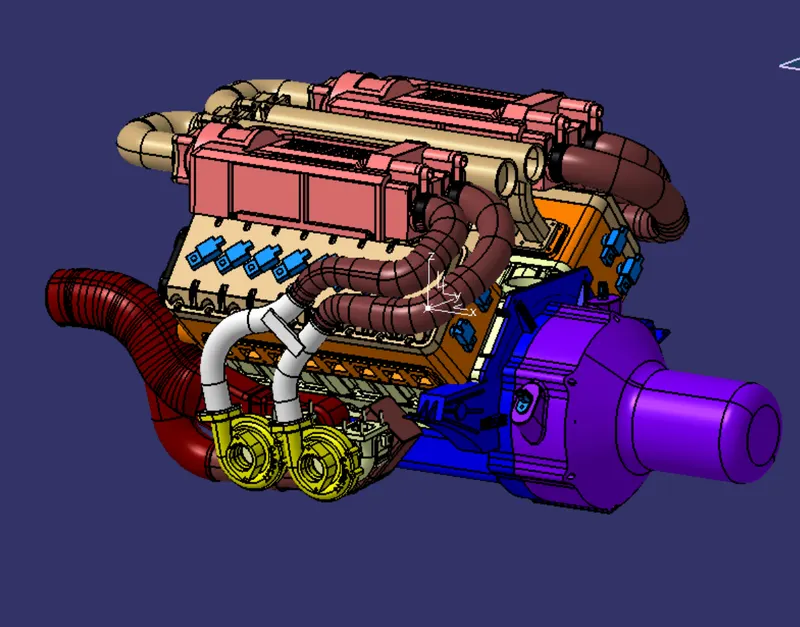
Objective:
- The objective of the project is to route the wiring harness on given Bugatti V16 Engine and prepare flatten view drawing in CATIA V5. All types of packaging rules have to be considered while routing the harness.
- Also, Industry best practices should be demonstrated in design. All the necessary details like clearance, clipping/clamping selection, harness fixing requirements, harness continuity should be provided in order to design wiring harness.
- The above figure shows the 16 valve Bugatti Engine where 8 cylinders are placed on the right side and 8 cylinders are placed on the left side.
- There are total 16 injectors where 8 injectors are used for 8 cylinders on right side and 8 injectors are used for another 8 cylinders on left side.
- Also there are 4 cam-shaft sensors, so there are total 20 sensors that we have to connected electrically.
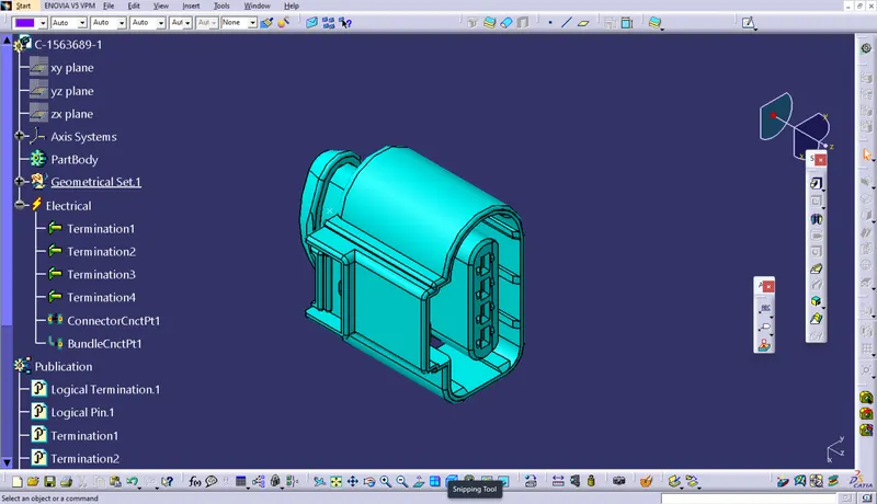
- Generally, 4-pole connectors are used for fuel injectors of the engine.
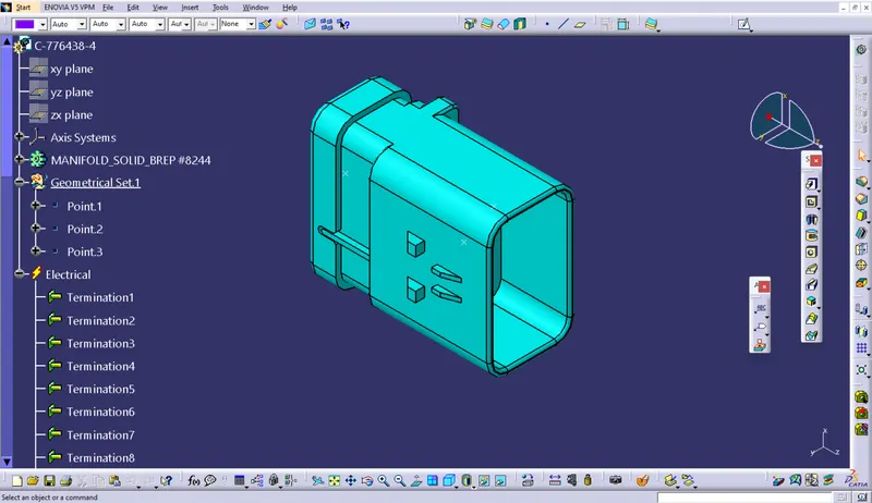
- The engine will also have an interconnection connector which will connect the engine to other parts of the vehicle. We will be using a 12-pole electrical connector with a mounting clip feature as an interconnection connector.
- The plastic guiding channel used in this harness should bemade of a Material that can withstand at least 150 degree Celcius.
- The bend ratio for the all bundle segmets should be 1.4.
Parts used in engine routing:
Connectors:
- Determining the appropriate type of connector depends on multiple performance factors, such as mating type, insulation needs, power contacts, and signal contacts. Configurations may also vary, with options including wire-to-wire, board-to-board, or board-to-wire.
- Connectors come in multiple designs, with 2-, 3- or 4-pin connectors being standard. When selecting a connector, it is crucial to know the necessary:
- Current rating
- Circuit density and size
- Engagement force
- Wire size
- Operating voltage
- Agency approvals
- Price per circuit
Connectors definition:
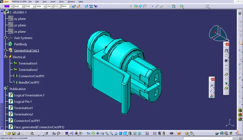
The following parameters are required to define any connector:
Geometry Parameters: Points & Co - ordinate system ( Axis ) .
Connector connection points: This point is used for the connection of one connector to another connector.
Harness bundle entry point: This point defines where the harness bundle segment point will end when routed to the electrical connector .
Cavity connection point (Optional ) : This point is used to define the connection of a connector to a connector clip . This only applies to connectors that have the mounting feature for a connector clip
Clips & Clamps:
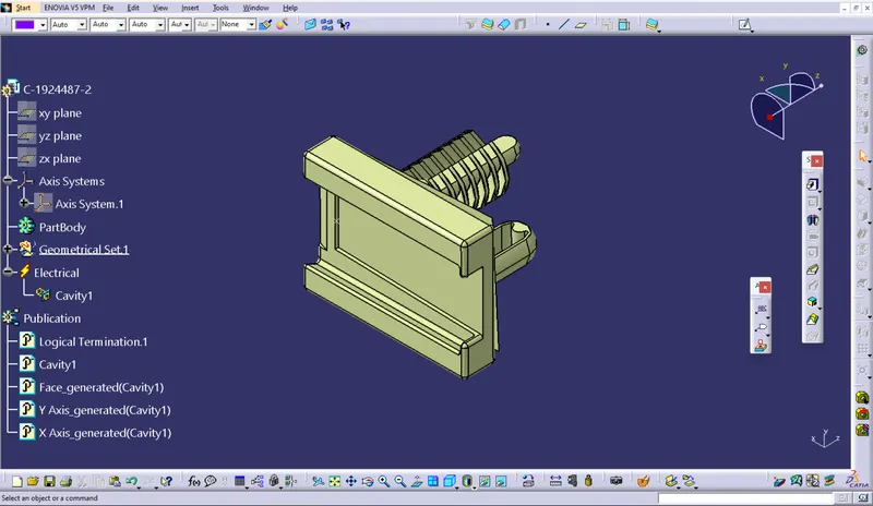
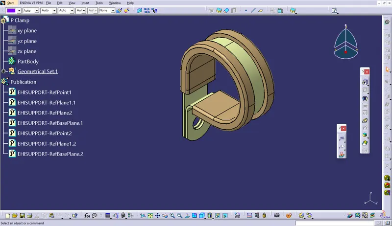
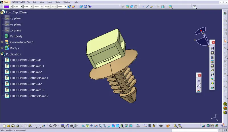
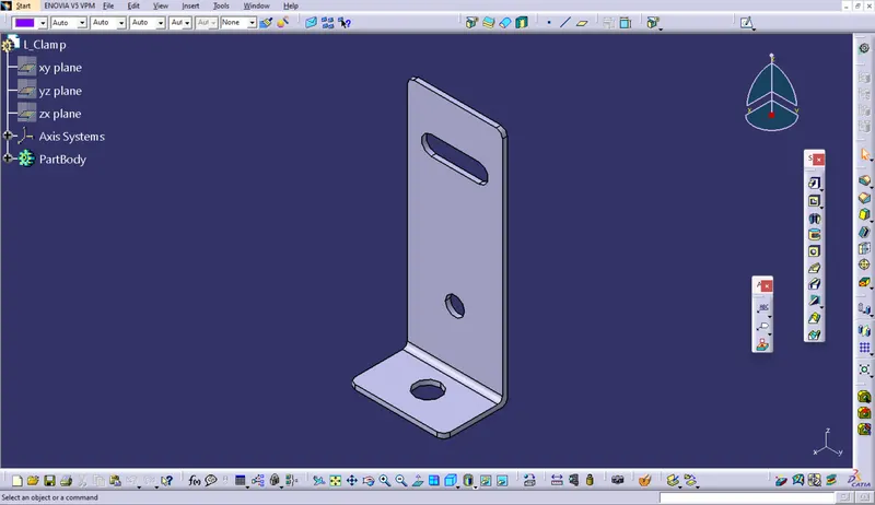
- Create Entry and Exit point
- Create two plane at the point and another plane in the base
- Switch into electrical part design
- Click on support definition - select part - select entry point - select entry plane, exit and base plane.
- Again Click on support definition - select part - select exit point - select exit plane and base plane as secondary plane is automatically taken.
Protect coverings:
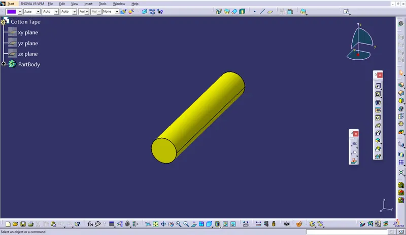
- Switch to Electrical part design
- Select Define protection Part
- Click on part (on file name in specification tree)
- Provide given parameters and bend radius as '1.5 x Outer Dia'.
Catalogue Creation:
- new part - catalogue document - add family - give name - type - select Conduit - save.
- Open part to add catalogue - store device command - select catalogue - family – Slit-cot-tube - ok.
Plastic Guiding channel:
-
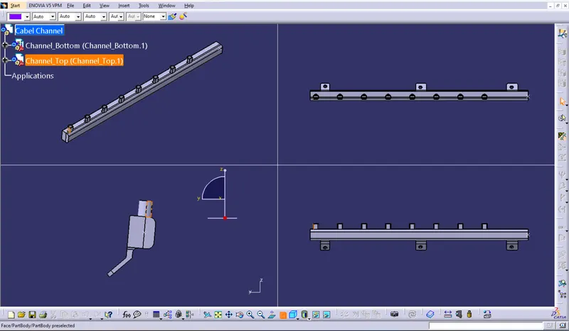
We have to add now plastic guiding channel because V16 engine has 8 injectors on right side and 8 injectors on left side which are very close to each other.
-
Hence plastic guiding channel is best option for proper and easy routing of the wiring harness.
-
It will reduce the complex wiring harness routing. We will require two different guiding channel for both right and left side of the engine.
-
Now, before placing guiding channel, we have to define geometrical parameters of guiding channel as below.
Geometrical bundle creation:
Step 1
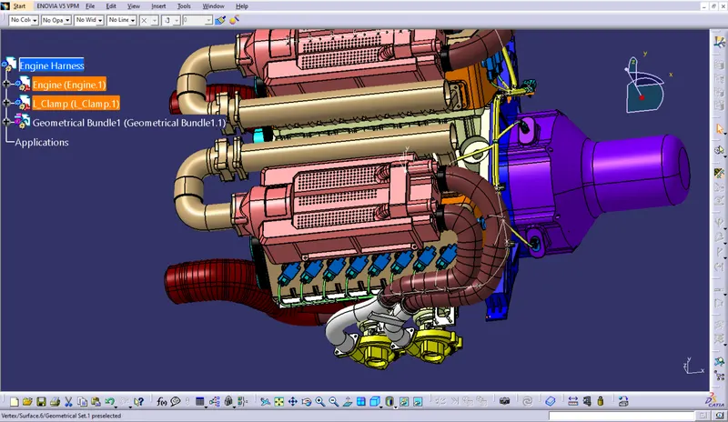
- Create harness using the electrical harness workbench.
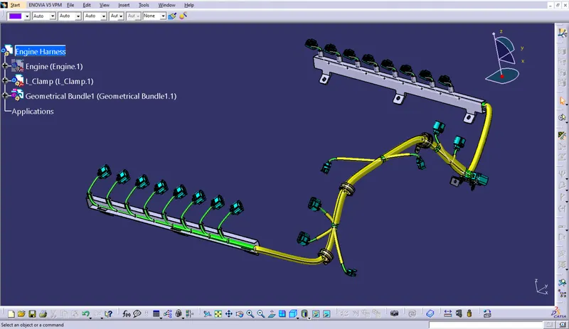
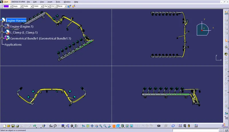
- First, all the connectors are placed at their desired locations. Second, bundle segments are created between the connectors with branch points and branches.
Step 2
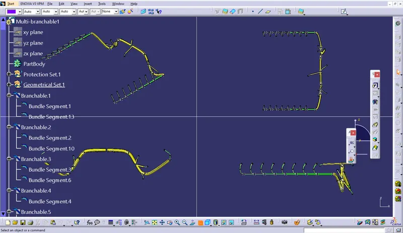
- After Harness A and Harness B are created the next step is to check the bundle continuity.
- First, we have to make sure multi-branchable is selected and then we have to go in Edit>Search>Advanced>Electrical Workbench>Type-Bundle Segment>Attribute-Fully Connected.
- Selecting the "FALSE" option will show all the connected bundle segments while selecting the "FALSE" option will show all the non-connected bundle-segments.
Step 3
- In this step, we have to interconnect the Wiring Harness electrically.
- copy both harness A and harness B and paste it into the newly created product file to make the final harness assembly.
Step 4
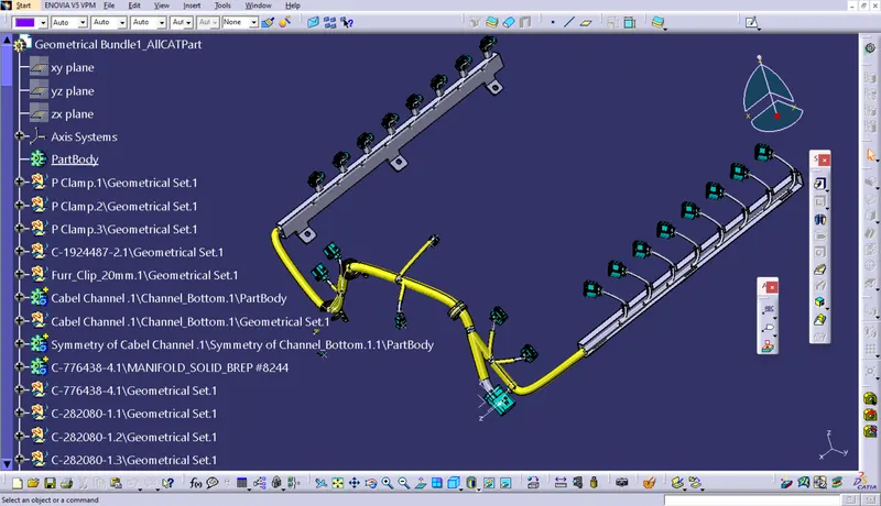
- In this last step we have to convert out Final Harness Assembly file into IGS format.
- The CAT part is created the whole product file is converted into a single part.
Flatterning:
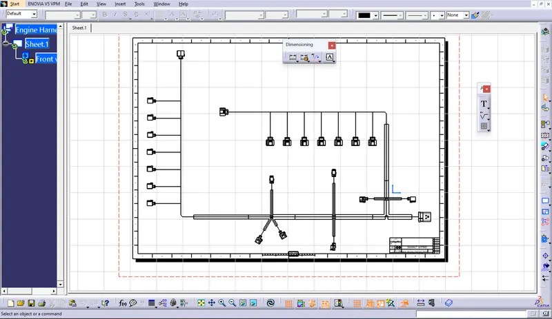
- Create a product file and navigate to the Electrical Harness Flattening for wire harness flattening option and save it in the same location where the wire harness or routing assembly is stored.
- Define the 'Harness flattening parameters' in order to flatten the required wire harness assembly.
- While defining the harness flattening parameters in the drawing menu single line is selected for bundle segment and double line is selected for protective coverings in order to differentiate between the wire bundle and cot tubes in drafting.
- Select the 'Extract' option from the Electrical Harness flattening workbench and select the Geometric bundle product in the wire harness assembly product file.
- Then wire harness assembly is imported to the Wire flattening product file with 'EHF' extension added to the geometric bundle assembly name.
- Select the 'Flatten' option to flatten the wire harness assembly.
- Then select the active plane, then select any one branch and then select the 'select all branches'.
- Save the product file using 'Save management' option so that all the related product files and part files are stored in single directory.
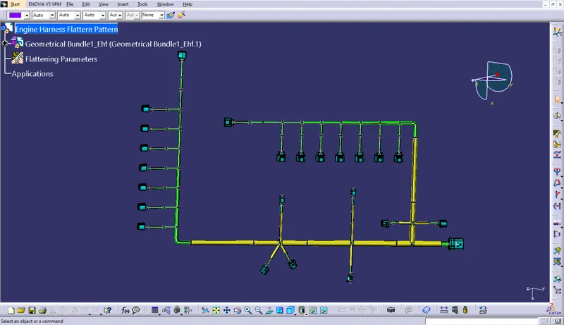
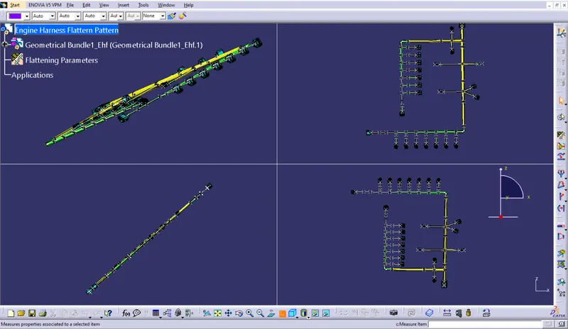
DRAFTING THE FLATTENING HARNESS ASSEMBLY
- Create a new drawing file and save the file in the same location.
- Add the front view of the harness assembly by selecting any one of the flat faces of the connector and orient the view as per the requirement.