Project 1
AIM OF THE PROJECT:
Design a battery pack for a car of roughly 150 kW with 120 V. Use 3500 mAh 3.6V nominal NMC chemistry cell.
a. Design the battery pack configuration.
b. Draw the BMS topology for this battery pack.
THEORY:
Battery management system (BMS) is technology dedicated to the oversight of a battery pack, which is an assembly of battery cells, electrically organized in a row x column matrix configuration to enable the delivery of a targeted range of voltage and current for a duration of time against expected load scenarios.
The oversight that a BMS provides usually includes:
- Monitoring the battery
- Providing battery protection
- Estimating the battery’s operational state
- Continually optimizing battery performance
- Reporting operational status to external devices
Here, the term “battery” implies the entire pack; however, the monitoring and control functions are specifically applied to individual cells, or groups of cells called modules in the overall battery pack assembly. Lithium-ion rechargeable cells have the highest energy density and are the standard choice for battery packs for many consumer products, from laptops to electric vehicles. While they perform superbly, they can be rather unforgiving if operated outside a generally tight safe operating area (SOA), with outcomes ranging from compromising the battery performance to outright dangerous consequences. The BMS certainly has a challenging job description, and its overall complexity and oversight outreach may span many disciplines such as electrical, digital, control, thermal, and hydraulic.
- The costs, complexity, and size of the battery pack
- Application of the battery and any safety, lifespan, and warranty concerns
- Certification requirements from various government regulations where costs and penalties are paramount if inadequate functional safety measures are in place
There are many BMS design features, with battery pack protection management and capacity management being two essential features. We’ll discuss how these two features work here. Battery pack protection management has two key areas: electrical protection, which implies not allowing the battery to be damaged via usage outside its SOA, and thermal protection, which involves passive and/or active temperature control to maintain or bring the pack into its SOA.
SOLUTION:
Given data:-
Required Power = 150 KW
Required Voltage = 120 V.
Battery details:-
Batatry capacity = 3500 mAh= 3.5 Ah
Battery Nominal Voltage =3.6V
First, find the two parameters as follows:-
i) Number of cells connected in Series
ii) Number of cells connected in Parallel.
Number of cells connected in Series
Cells connected in series =Required voltage /Nominal cell voltage
=120/3.6=33.33.
Rounding it off to 33 or 34
| Parameter |
Case I: 33 |
Case I: 34 |
| nominal battery voltage =no.of cells in series *cell nominal voltage | 33*3.6=118.8 | 34*3.6=122.4 |
When compared with the rated voltage, the battery voltage is greater in case 2 than in case 1.
So, Its always better to have more voltage
No.of cells in series= 34
Number of cells connected in Parallel:-
Required Power = 150 KW
Required Voltage = 120 V.
∴ current =power/voltage
=150*1000/120
=1250A
Batatry capacity = 3500 mAh= 3.5 Ah
Battery Nominal Voltage =3.6V
No. of parallel cell=motor continuous current/cell nominal capacity
=1250/3.5
No. of parallel cells =358
∴ The battery pack configuration is 34S358P
BMS topology for this battery pack
Generalized topology of BMS:
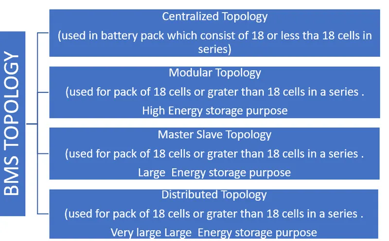
Based on these cells connected in series and the Architecture of BMS we Choose the Master and Slave topology of BMS for this Ev battery pack Topology design.
BMS Topology MODEL:-
Master and Slave Topology:-
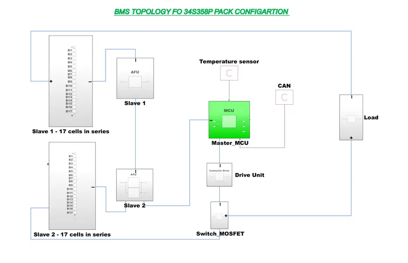
>>This Topology consists of 2 numbers of slaves of AFU units with each AFU unit's slave Consisting of 17 numbers Of Cells connected in series.
Conclusion:-
We can conclude from the above calculations the battery Pack configuration is 34S358P
Well-suited Battery BMS Topology is a "Master and Slave " Topology.
2. Build a 3S2P battery pack configuration with a generic battery block using Matlab/Simulink.
Aim: Building a 3S2P battery pack configuration with a generic battery block using Matlab/Simulink.
Procedure:-
Batteries in 3S2P configuration in Matlab/Simulink. That is 3 cells should be connected in series and 2 cells should be connected in parallel.
Hence total no. of cells in battery pack =3*2= 6 cells.
It is 3s2p connection, In the series, negative terminal of a battery is connected to the positive terminal of the battery,
The figure shows the battery connected in series and parallel combinations. 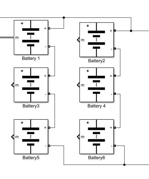
Model Explanation:-
The voltage measurement block is connected across the battery pack to measure the battery pack voltage. The scope output used for the battery pack consists of SOC (State of Charge), Current, and voltage. The controlled current signal is given as the load to the battery pack. The constant block is determined with battery capacity and it is given to the controlled current block.
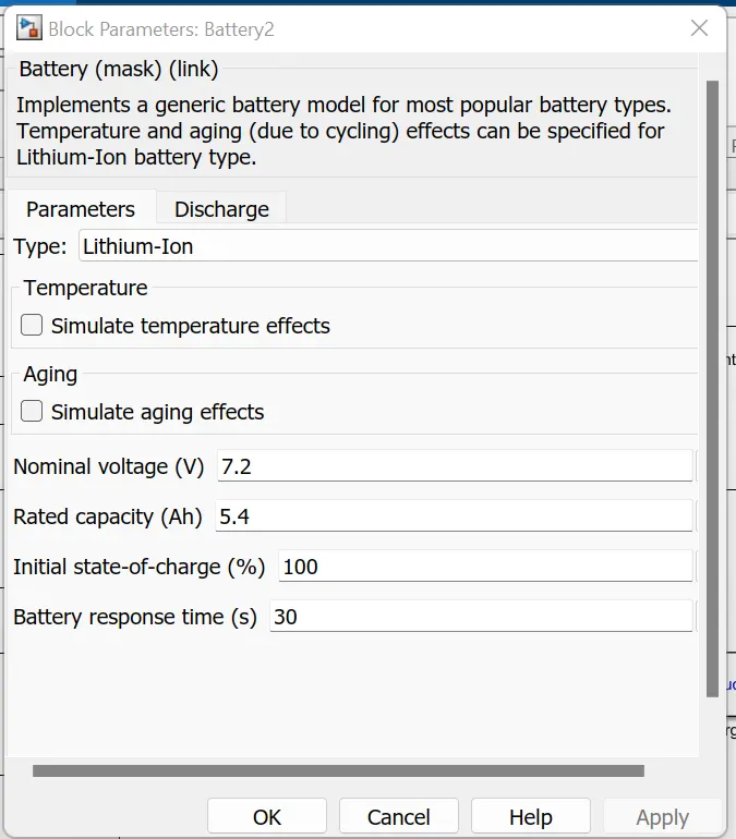
The parameter given inside the battery is given below:-
- The nominal voltage of a cell 7.2V
- Rated capacity of a cell 5.4Ah
- The maximum voltage of a cell is 8.3V
Nominal voltage of the battery pack = no.of cell in series * nominal voltage of a cell
= 3 * 7.2v
= 21.6 V
Rated capacity of the battery pack = no.of cell in parallel* rated capacity of a cell
= 2 * 5.4Ah
= 10.8Ah
This battery pack has 21.6V with a 10.8Ah battery capacity
Overall voltage of the battery pack = maximum voltage of the battery * no. of cells in series
= 8.3V * 3
= 24.9 v
Overall voltage = 25 V
Simulink model:-
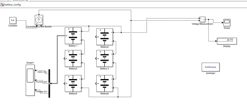
Blocks used:
1. Battery: The Battery block implements a generic dynamic model that represents most popular types of rechargeable batteries.
from this battery model, we will get 3 output value
1. SoC%
2. Current &
3. Voltage
2. Voltage Measurement Block: For measurement of voltage of battery pack.
3. Controlled current source: to discharge the battery, we have to use a Controlled Current Source
Output Result:
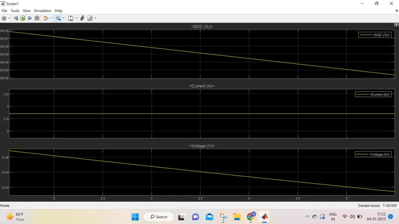
from the above plot, it is clear that voltage and soc reduced as we applied a load of 5.4
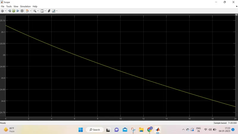
From the Above Plot, we can observe that the total battery pack voltage is reduced bt 10% of the initial value.
Conclusion: Thus we observed the SOC voltage and current of the battery pack configuration of the 3s2p battery, with the help of Simulink.
**Simulink model is attached with this**