Project 1
Aim:-
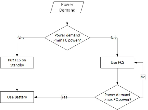
Create a stateflow or Simulink model for the following flowchart.
Load the .mat file into the workspace.
The input to the model would be the power demand.
The output should be:
- Fuel cell power
- Battery power
- FC Operating state (running, standby)
Create plot of these outputs against time.
Simulink module:-
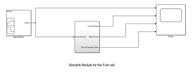
Description :- In that module we need components first ot build the module.
The components are signal builder, scope, Constant block, add block, interval test block, input block, output block, and the switch.
to build the module we have first given the power demand, our next steps are based on the power demand .
Steps:-
We have given the input through the siganl builder block, in that signal builder block we feed the power demand, this block is connected to the subsystem, In the subsystem its takes the input form the power demand and there are three condition for that,
| Supplied by | Power Demand |
| Battery | 0 - 100 |
| Fuel Cell | 101 - 1000 |
| Battery | 1001 - 1200 |
if the power demand is between the 0 to 100 it supplied by the batttery , and if the power demand between the 101 to 1000 power demand is supplied by the fuel cell and if the power demand is increases over to 1000 it is supplied by the battery.
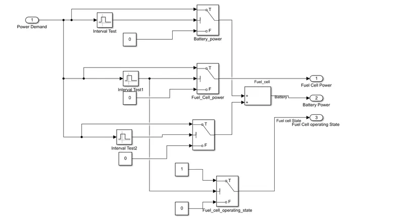
The input of the power demand is connected to the interval test block in the interval test block it sets the limit upto the selected range for the battery there are two interval test block is used one is set on the 0-100 and another is set on the 1000 - 1200 and third one is set in the 101 - 1000 it is used for the fuel cell. the interval block is connected to the switch,
The switch mechanism is like that , Pass through input 1 when input 2 satisfies the selected criterion; otherwise, pass through input 3. The inputs are numbered top to bottom (or left to right). The first and third input ports are data ports, and the second input port is the control port. The criteria for control port 2 are u2 >= Threshold, u2 > Threshold or u2 ~= 0.
then after the switch is connected to the add block and after that it is connected to the output. We have used the same prodecure for connecting the block for another condtion.
Subsystem module:-
Result:-
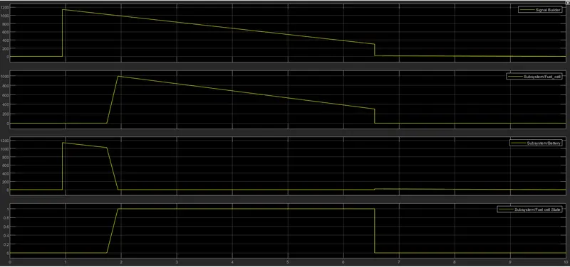
It is clearly undeerstood that when the power demand is between 101 to 1000 the output is 1 and it is indicating that the operating state of teh fuel cell is on. and power below 100 and above 1000 the output is 0 and it is indicating that the operating state of the fuel cell is off.
Also i have attached the module for that please see.