Project 1
AIM:
Designing a battery pack configuration for a car with NMC cell chemistry and BMS topology for the battery pack.
Building a 3S2P battery pack configuration in MATLAB/Simulink with a Generic battery block.
Objective-1:
- Design the battery pack for the car 150Kw with 120V. Use 3500 mAh 3.6V nominal NMC chemistry cell.
Cell capacity = 3500mAh = 3.5Ah
Cell Nominal voltage = 3.6V
Battery pack power = 150Kw
Battery pack voltage = 120V
Number of cells in series = Total voltage/Nominal voltage of the cell
Number of cells in series = 120/3.6
Number of cells in series = 33.3
Case-1: Rounding off 33.3 to 33
Nominal battery voltage = cell nominal voltage * 33
Nominal battery voltage = 3.6 * 33 = 118.8V
Maximum battery voltage = cell max voltage * 33
Maximum battery voltage = 4.2*33 = 138.6 v
Minimum battery voltage = cell minimum voltage * 33
Minimum battery voltage = 2.7 * 33 =89.1V
Case-2: Rounding off 33.3 to 34
Nominal battery voltage = cell nominal voltage * 34
Nominal battery voltage = 3.6 * 34 = 122.4V
Maximum battery voltage = cell max voltage * 34
Maximum battery voltage = 4.2*34 = 142.8v
Minimum battery voltage = cell minimum voltage * 34
Minimum battery voltage = 2.7 * 34 =91.8V
In the case-1 cell nominal, the voltage is lesser than the total voltage, case-2 voltage is meet the requirements.
The number of cells in the series is taken as 34 cells.
Number of cells in parallel = total current /cell capacity
Total current = power/voltage
Total current = 150K/120 = 1250A
The number of cells in parallel = 1250/ 3.5
The number of cells in parallel = 357.14
Number of cells in parallel is taken as 357 cells.
1.a. Design battery pack configuration.
To design a battery pack the main parameters are
Number of Series connected cells
Application
The number of series-connected cells is 33, and the battery pack is used for a Car.
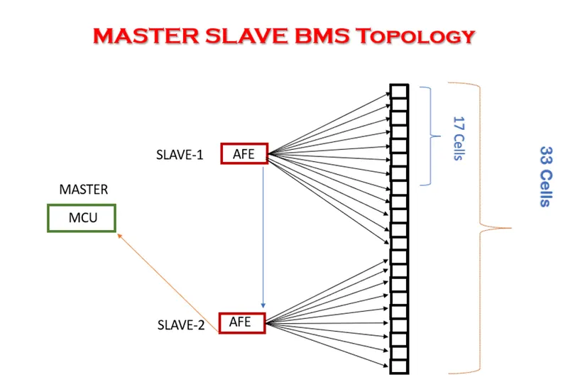
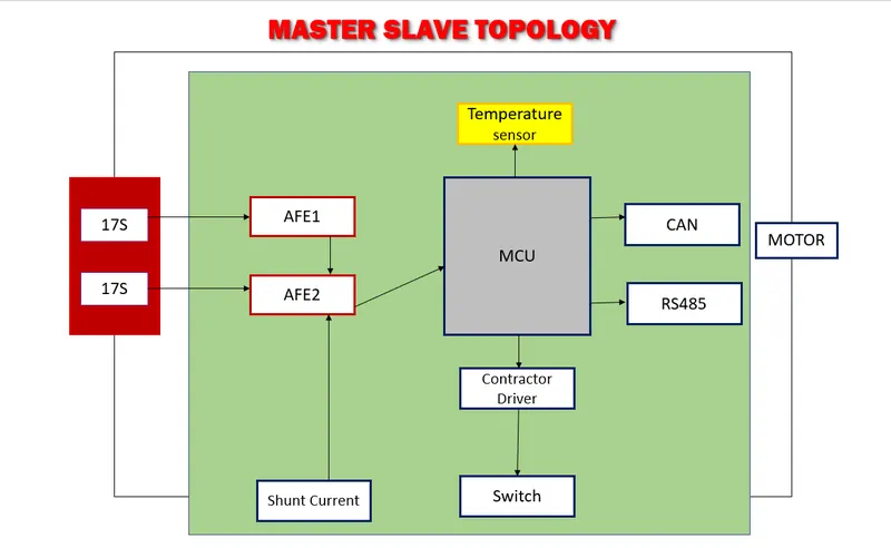
Master slave topology is used for this battery pack.
This topology has one master controller and two slave controllers. Each slave controller has 17 cells connected in series.
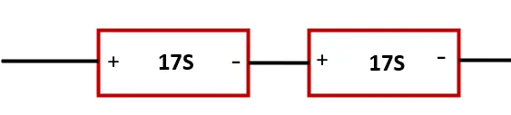
- b. Draw the BMS topology for this battery pack.
Master slave topology is shown below for the above battery pack configuration.
- Build a 3S2P battery pack configuration with a generic battery block using MATLAB/Simulink.
Answer:
The given battery pack configuration is 3S2P.
3 cells in Series and 2 cells connected in Parallel.
Total number of cells in battery pack = no. of cells in series * No. of cells in parallel
= 3 * 2 = 6
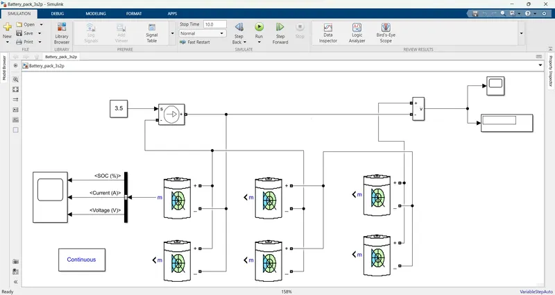
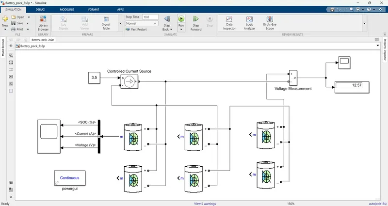
The simulation model is shown below:
Model Explanation:
To build the 3S2P battery pack configuration with a generic battery pack, I am taking the 3 cells in series and 2 cells in parallel connection. The voltage measurement block is connected across the battery pack to measure the battery pack voltage. And a display block is connected to voltage measurement to view the measured voltage and a scope block is also connected to view the graphical waveform. The controlled current source block is connected battery pack and the controlled current signal is given as the load to the battery pack. The constant block is connected to the controlled current source block ‘s’ port and it is determined by the battery capacity. A scope block is connected to the battery pack through the bus selector to view the ‘SOC’, VOLTAGE, and CURRENT.
The Battery parameters are shown below:
Nominal voltage of the cell is 3.6V
Rated capacity of the cell is 3.5Ah
Maximum voltage of the cell is 4.2V
The nominal voltage of battery pack = Number of cells in series * nominal voltage of a cell
= 3 * 3.6
= 10.8V
Rated capacity of the battery pack = Number of cells in parallel * Rated capacity of the cell
= 2 * 3.5
= 7Ah
The overall voltage of the battery pack = maximum voltage of a cell * no of cells in series
= 4.2 * 3
= 12.6V
The overall voltage of the battery pack is 12.6V
Results:
the simulation is run for 10 seconds. and the results are shown below.
overall output voltage measured from voltage measurement:
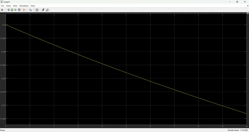
In the above plot, we can observe the voltage is decreses from 12.6v to 12.57v
Battery individual cells parameters (SOC, VOLTAGE, and CURRENT):
single cell battery voltage, current, and SOC are observed individually in the below plots.
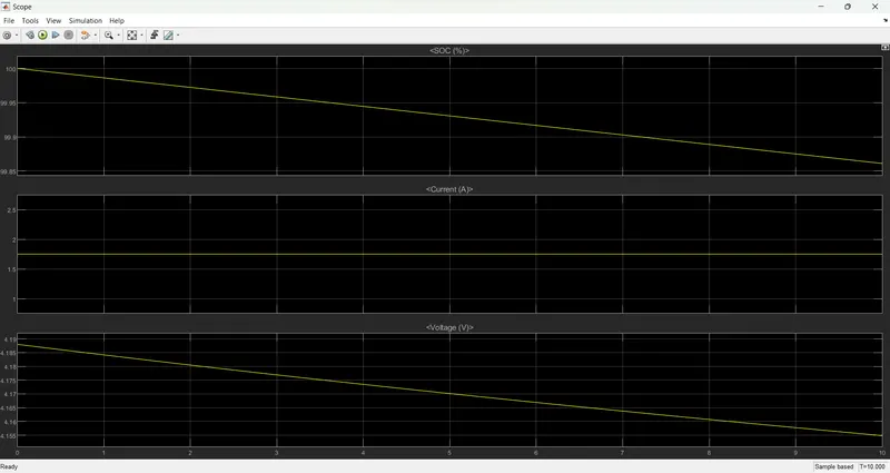
- SOC reduced from 100% to 99.86%.
- The current value is 1.75 A and is determined by the load.
- The voltage decreases from 4.2v to 4.15v.
Conclusion:
The battery pack for car is designed with given battery pack and cell specifications.
The master slave topology is selected as per the battery pack parameters and this topology is drawn.
Simulink model for 3S2P Battery pack configuration with generic battery block is developed.