Project 1
Aim: To determine wind load, earth pressure, seismic loads, dead load & IRS live load acting on bridge and analyze accordingly in Staad.Pro.
Introduction:
The objective is to calculate wind load, earth pressure, seismic loads, dead load & IRS live load from the given data manually and attempt the same in Staad.Pro for the bridge and analyse the results and effects on the structure.
The Illustrated bridge is located at Ahmedabad, India spanning of 240m in length and width of 22m carrying metro train loading in both opposite directions. The complete bridge is constructed underground retaining soil pressure by the structural RCC wall. And under platform to excess trains and manage other utilities.
Bridge is to be analysed under the clauses of revelant latest codes of practice such as IS1893 for seismic load and IS875 for Wind load.
________________________________________________________________________________________________________________
Given Data (for calculation):
Width of Bridge = 22m
Location = Ahmedabad
Length of Bridge = 240m
Density of Soil = 18 KN/m3
Assumption:
It is assumed that bridge is resting on medium type soil and water level is below the foundation level of bridge.
Weight of the utilizes such as sanitary pipes, fire hydrant, light lamp etc. is ignored in staad model and manual calculations.
Seismic weight of trains load is ignored in analytical results and calculations.
Coefficient of internal friction of soil (Φ) = 30 degree
Damping Ratio = 5% = 0.05
Surcharge due to the vehicular load on the above deck is being ignored as well.
________________________________________________________________________________________________________________
Procedure:
All the loads are calculated in such a manner as mentioned below,
Dead Load = Self weight of the structure is calculated by the factor in the given staad model while other utilizes load has been ignored.
Metro Rail Live Load (Vehicle/Moving Load) = According to IRS metro rail loading, loads are considered as follows,
Loading is considered of Metro Rail of 21.1m long in length & width of 1.8 m having,
- Axle Loading = 17 tons (170KN)
- Maximum Number of cars = 6 nos.
- Number of wheels each side = 4 nos.
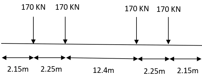
Span of bridge for calculations = 10 m
Length of metro rail vehicle = 16.9 m
Increment per combination = 1 m
No. of Load combination = (span of bridge + length of vehicle) / increment per combination
= (10+16.9)/1
= 26.9 ≈ 27
Earth Pressure = Loads are calculated as,
Height of wall for earth to retain (H) = 20 m
Density of Soil (ϒ) = 18 KN/m3
Coefficient of internal friction of soil (Φ) = 30 degree
Coefficient of active earth pressure (Ka) = (1-sin Φ)/(1+sin Φ) = (1-sin 30)/(1+sin 30) =1/3
Pressure at bottom of wall (Pa) = Ka x ϒ x H = 0.333 x 18 x 20 = 120 KN/m2
Seismic Loads = Earthquake loads are calculated by the consideration of following factors mentioned below:
According to IS 1893:2016,
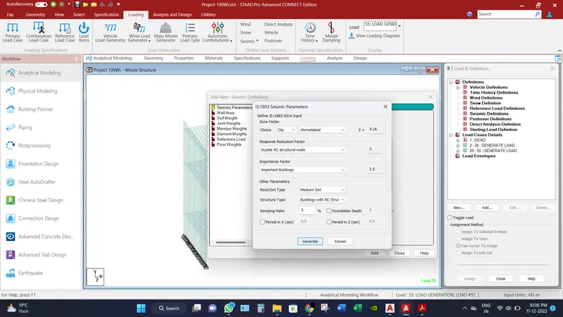
Since location is at Ahmedabad, so site lies in seismic zone 3 [Refer Annexure E of IS1893 (Part 1)]
Seismic Zone factor = 0.16 [Refer Table 3 of IS1893 (Part 1)]
Response Reduction Factor = 3 [Refer Table 9 of IS1893 (Part 1)]
Type of soil = Medium soil [As per assumption]
Damping Ratio = 5% = 0.05 [As per assumption]
Importance Factor = 1.5 [Refer Table 8 of IS1893 (Part 1)]
Since the structure is under ground and only the small section of whole bridge is been analyzed for only one direction in both negative and positive axis.
Wind Load = Structure will not be analyzed for wind load since the whole structure is under ground. So, ignore the wind loads.
________________________________________________________________________________________________________________
Computer Proficiency:
- Since the Staad model is already provided, provision of load only be provided as per mentioned above. In order to do that, go to loading tab and add “Dead” load as per load cases.
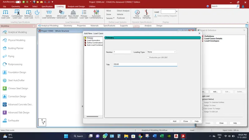
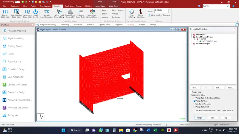
- In the dead load case, add self-weight and assign to the whole structure via a function of “Assign to view”.
- For the metro rail live load, define the vehicle load as mentioned above. Refer image below.
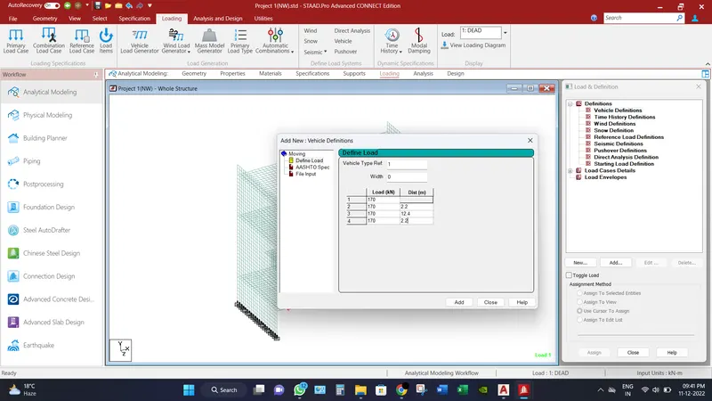
- Then after in load cases, create number of load combination as calculated above. Refer image below.
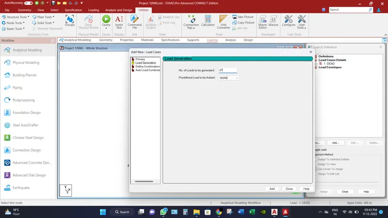
- And accordingly provide the loading in the specified position as per figures provided in question, as values for an instance, initial position of load is 1.5m in x coordinate, 3.5m in y coordinate and -16.8m in z coordinate and increment of 1 m in z direction having range of 10 in z direction. Refer image below.
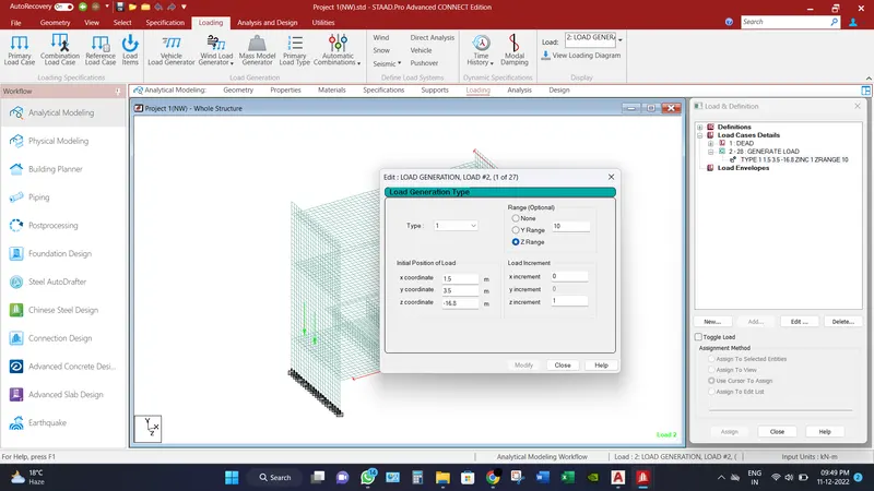
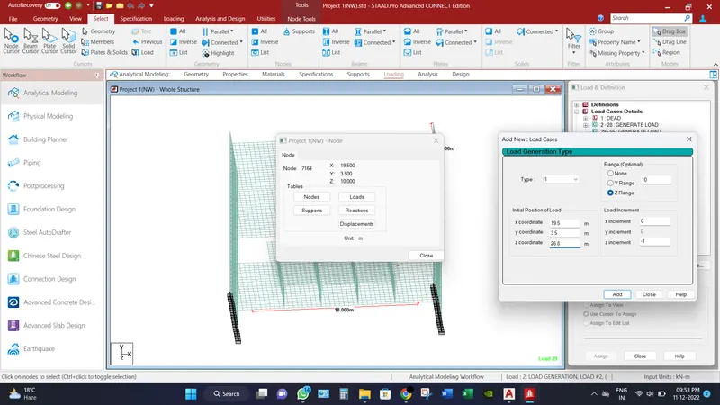
- Accordingly provide the train loading in the different position traveling in opposite direction. Refer image below.
- After that definition of seismic loads has been carried out by the consideration of factors as mentioned above. Make sure the seismic load will be provided to model in load cases before 8 load cases only. This can be improved by editing the previous provided loading in command file option.
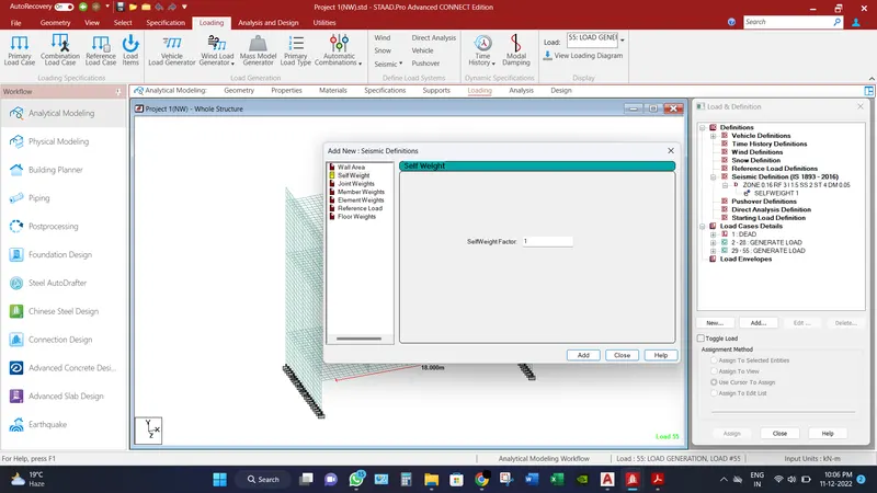
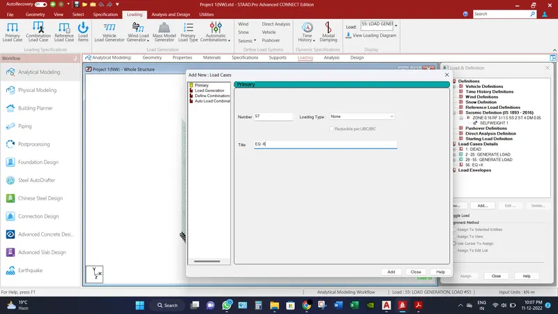
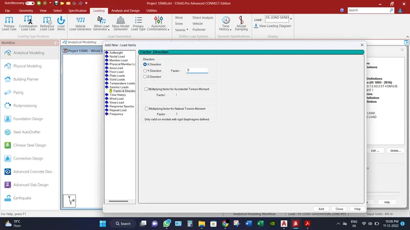
- After definition, Load cases are added to list in x direction only as discussed above in both -ve and +ve directions. Refer images below.
- In order to assign the loads to the structure, only one case is taken into consideration as earth pressure due to backfill. As per Earth pressure due to backfill is provided in the form of hydrostatic force (Trapezoidal Force) as per above calculations by interpolating in y direction and pressure in positive x direction for left side of wall and assign to the selected plates.
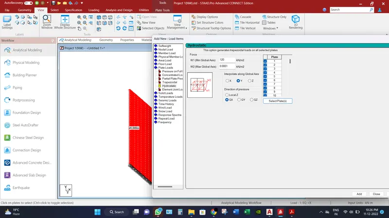
- In the same manner, right side of wall is also provided by the earth pressure loading. Refer image below.
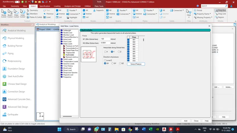
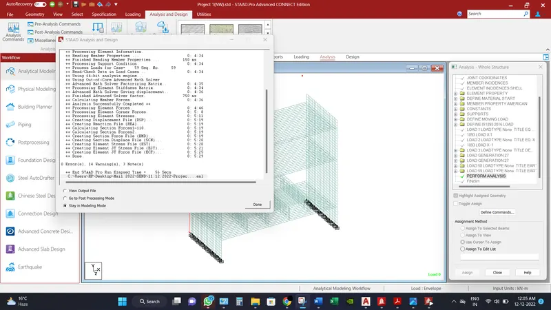
- After all the provision of loading is provided, then go to analysis tab and click “Run Analysis”.
________________________________________________________________________________________________________________
Analytical Results:
Bridge has been analyzed and check for different load combination and different displacement for different scenarios has been record. All the result that is presented are of the critical situation of among within the envelope.
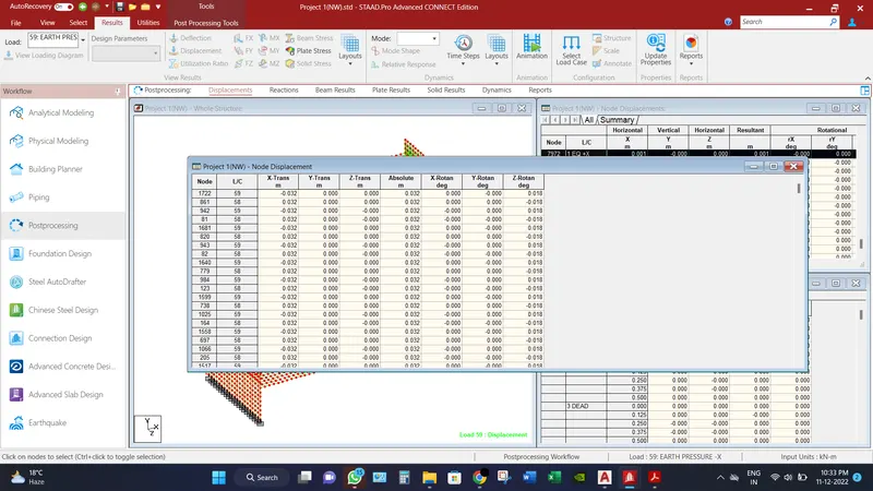
Maximum node displacements is recorded as 32 mm.
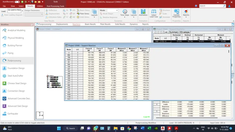
Maximum Base reactions are recorded axial force as 869.019 KN and moment as 172.3 KN-m.
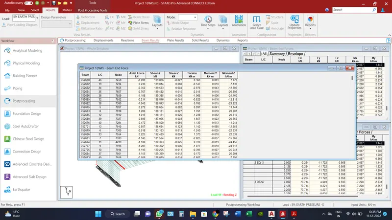
Maximum shear force recorded in beam in Fy direction is 139.836 KN.
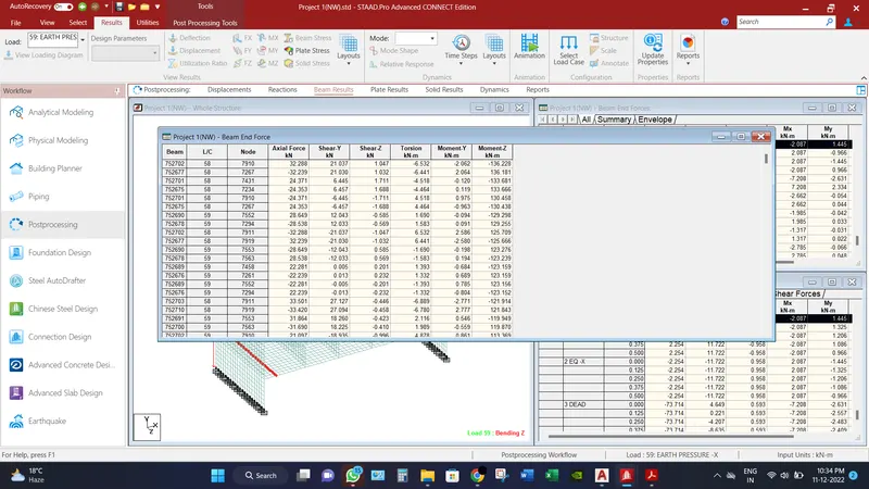
Maximum Bending Moment recorded in beam in Mz direction is 136.228 KN-m.
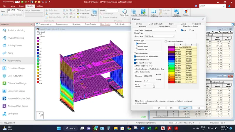
Maximum Shear Force in SQX (local) direction for deck slab is recorded as 911.151 KN/m2.
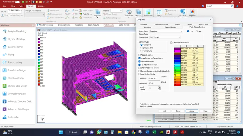
Maximum Shear Force in SQY (local) direction for deck slab is recorded as 573.911 KN/m2.
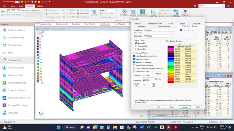
Maximum Moment in MX (local) direction for deck slab is recorded as 2037.29 KN-m/m.
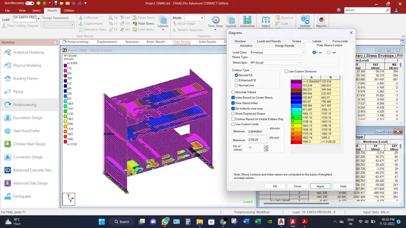
Maximum Moment in MY (local) direction for deck slab is recorded as 2128.22 KN-m/m.
__________________________________________________________________
Conclusion:
Different results have been found under all the load cases as,
Maximum node displacements is recorded as 32 mm.
Maximum Base reactions are recorded axial force as 869.019 KN and moment as 172.3 KN-m.
Maximum shear force recorded in beam in Fy direction is 139.836 KN.
Maximum Bending Moment recorded in beam in Mz direction is 136.228 KN-m.
Maximum Shear Force in SQX (local) direction for deck slab is recorded as 911.151 KN/m2.
Maximum Shear Force in SQY (local) direction for deck slab is recorded as 573.911 KN/m2.
Maximum Moment in MX (local) direction for deck slab is recorded as 2037.29 KN-m/m.
Maximum Moment in MY (local) direction for deck slab is recorded as 2128.22 KN-m/m.