Project 1
| WIRING HARNESS FOR ENGINE ASSEMBLY |
AIM:
To Route the Wiring harness on Given Engine and Prepare flatten view drawing in CATIA V5.
OBJECTIVE:
The objective of this project is to route the wiring harness and prepare flatten view drawing for the tailgate of the car. All types of packaging rules have to be considered while routing the harness and industry based practices shall be demonstrated in harness design. All necessary details like clearance, clipping/clamping selection, harness fixing requirements, harness continuity should be provided in order to design the wiring harness.
| DESIGN CRITERIA AND PACKAGING ASSUMPTIONS |
- Wiring harness should be routed in such way that it is easy to assemble and access.
- Easy manufacturing, installation, removal and maintenance have to be considered while designing the wire harness.
- Wiring Harness should be kept away from sharp environment like edges, corners etc.
- Avoid harness routing and clipping in the blind zones or hard to reach areas during harness assembly or service.
- Provide additional slack if needed according to the surrounding and harness bending requirement. If harness is passing through the closures/doors or tail gates then envelope dimensions during opening and closing of doors shall be considered to provide the slack. Check the harness slack requirements with open and close conditions to avoid excess slack.
- Routing through small structural holes and openings shall be avoided. To minimize chaffing and handling of the wiring harness during installation.
- It should be make sure that there is no case of fouling while designing the wiring harness in the CAD environment. Additional mounting equipments like clips/clamps may be used to avoid fouling.
- Use of rubber grommet is recommanded if harness is passing through sheet metal panels. Example- firewall, passing to door, tail gate etc.
- The branch length should be greater than 50mm.
- The minimum distance between the clip and branch point should be at least 25mm.
- The minimum distance between the two branch points should be at least 50mm.
- Clips/clamps used for the wiring harness should be easily available in the market to avoid extra cost for custom mounting solutions.
|
Now, we have to route wiring harness for two tail lights and two number plate lights, and connect them to main electrical system of car.
|
| PROCEDURES |
ELECTRICAL COMPONENT DEFINITION
1.CONNECTORS
|
1. Create 3D object/Get from vendor |
| 2. Define Geomentrical parameters |
| 3. Define the 3d object as a connector |
|
4. Define connection points |
Geomentrical Parameters Definition
It's mandatory to create geomentrical parameters such as points and coordinating system in given comoponent to define connection points.
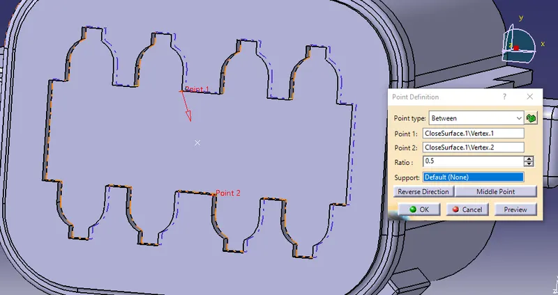
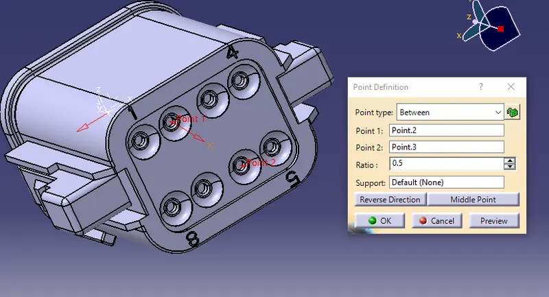
Above image shows pont creating on other side of connector to create bundle connection point.
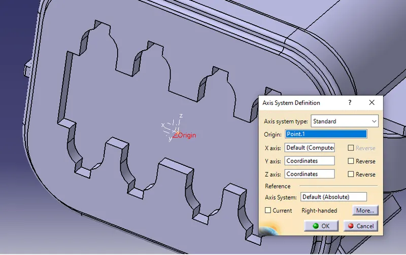
conditions - Y axis should be in the mating direction
x axis should be in the locking mechanism direction
z axis should be in the direction towards top surface
Defining the connector to create connection points,
To create connection points we should have a electrical equipment like connectors, we should define the part or 3d object as an electrical device.
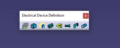 ->Definition toolbar to define the given object as electrical
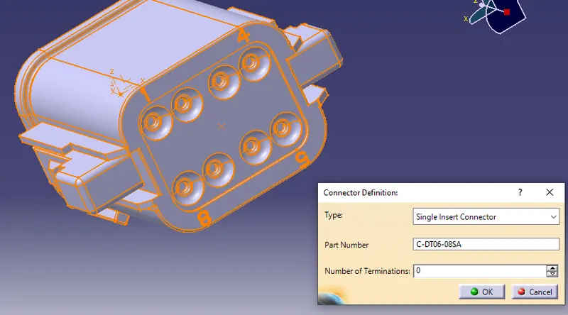
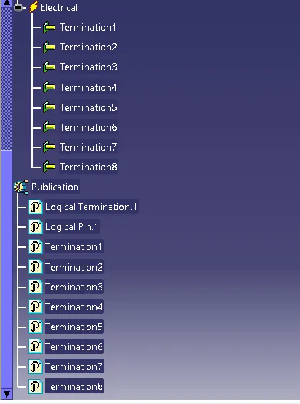
The above image shows The properties of electrical Device.
Connection Point definition
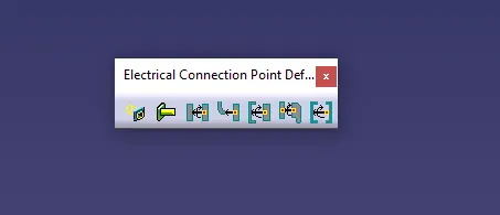 -> this is the toolbar in electrical part design to define connecting points.
Bundle Connection point
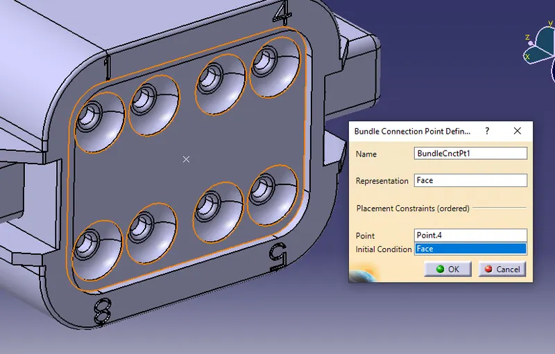
This is the point where bundle segment or wire point end when get routed to a connector. This point is known as Bundle Connection Point. At the time of defining bundle connection point, the number of terminals and a face is also provided as an input data.
Connector Connection point:
A connection point is a point in an electrical connector where a cable begins or ends. Electrical connectors are required to have at least one connection point with the route type set to Electrical. This defines the part as an electrical connector and provides information about the route
This point also used to make an assembly with other systems. This willl be defined by geomentrical parameters that we have already created.
- In Connector connection axis system, we have to always ensure that y-axis should be alwyas in the direction of mating axis of all the connectors.
- And x-axis should be in the diretion of locking mechanism and z-axis should be left-right side of the connector according to the orientation.
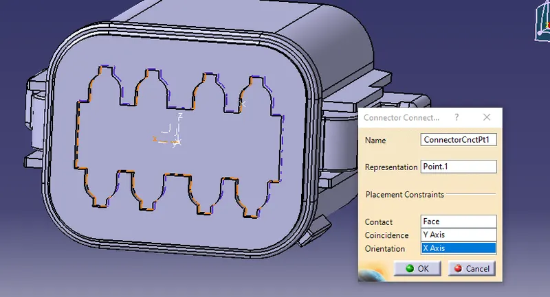
After defining the given component as electrical it will be added in geomentrical bundle to start routing.
2.P CLAMP
3.FURR TTREE CLAMP
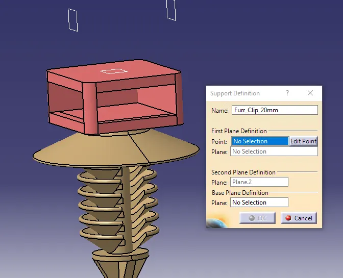
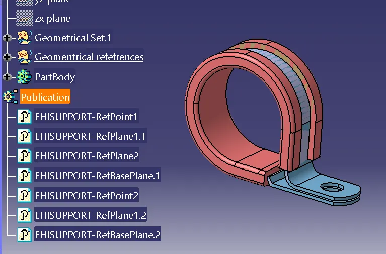
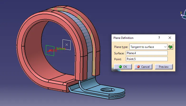
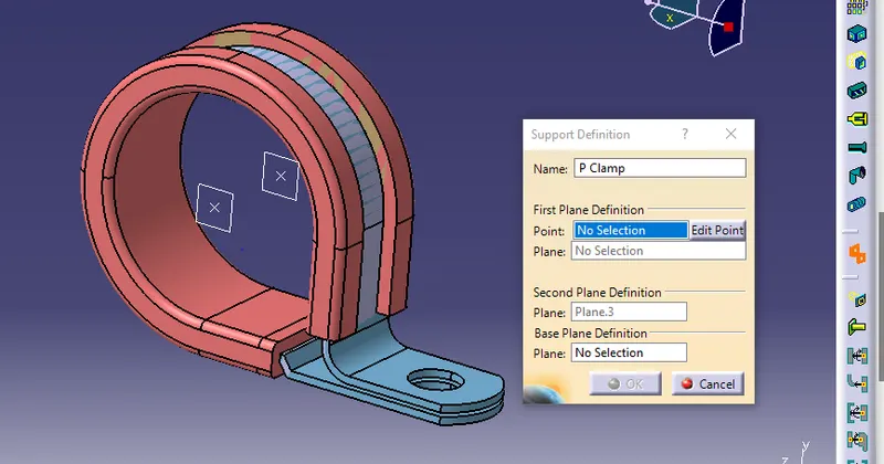
The above image showing that creation of supporting elements, where these plans is used as an entry end exit of bundle segment.
| ROUTING |
| The Harness Context Assembly |
| Geomentrical Bundle |
| Electrical Bundle |
The harness context assembly:
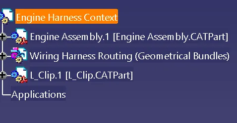
This is the top_level product file that contains the harness geometrical bundle/assembly and the wire harness electrical bundle.
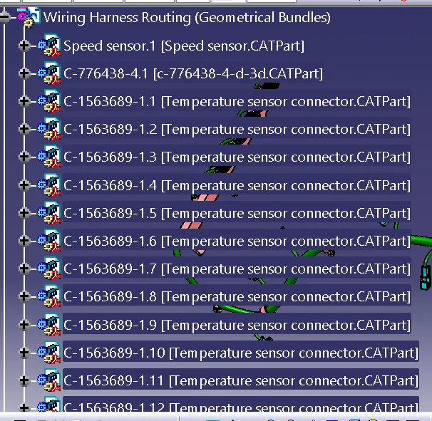
Geomentrical Bundle:
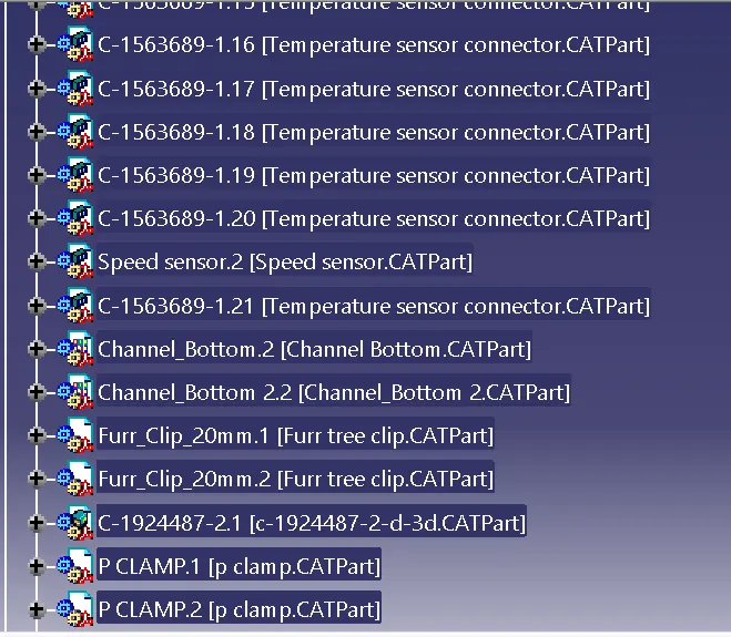
This sublevel product file is the wire harness product that contains all of the harness components i.e clips , supports, Connectors, splices,annotations and actual physical bunsle segments and branches.
Electriacl Bundle:
This sub level product file contains all of the electrical circuit information.
| GEOMRNTRICAL BUNDLE |
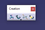 -> Toolbar to Define geomentrical bundle
By using the creation tool bar the product file can changed the geomentrical bundle, which is electrical product. It can be defined by a symbol which will be added to the product file.
| MULTI BRANCHING |
-> toolbar for multi branching
Bundles are developed between two electrical components by using bundle definition point.
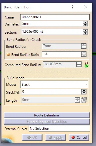
The above image shows creation of bundle.
Bend radius_used to specify flexilibility of bundle. The radius should be minimum of 1.4 times of the bundle Diameter.
Build mode_ used to give extra length The place where the extra lengths are needed.
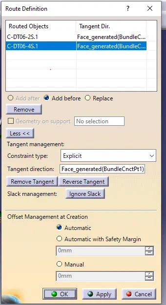
The above images shows, slecetion of connectors.
Tangent Management_ to create tangents on bundle based on connector ends.
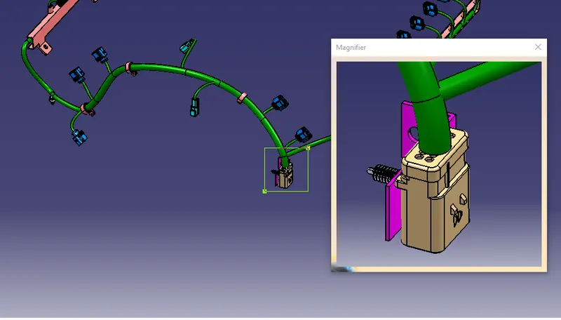
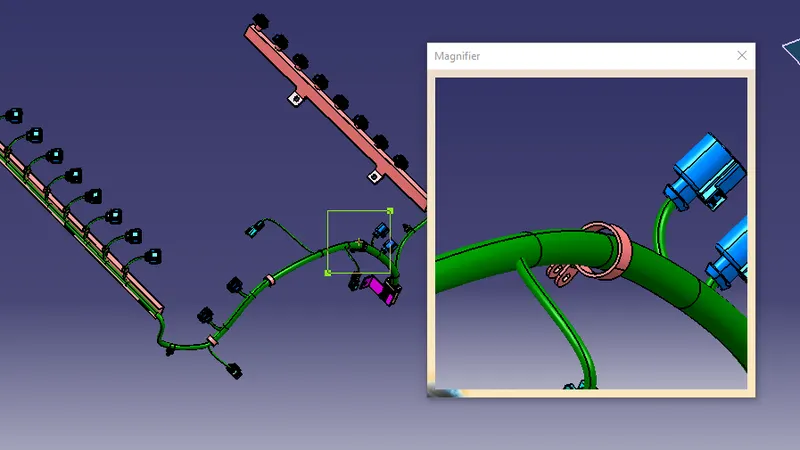
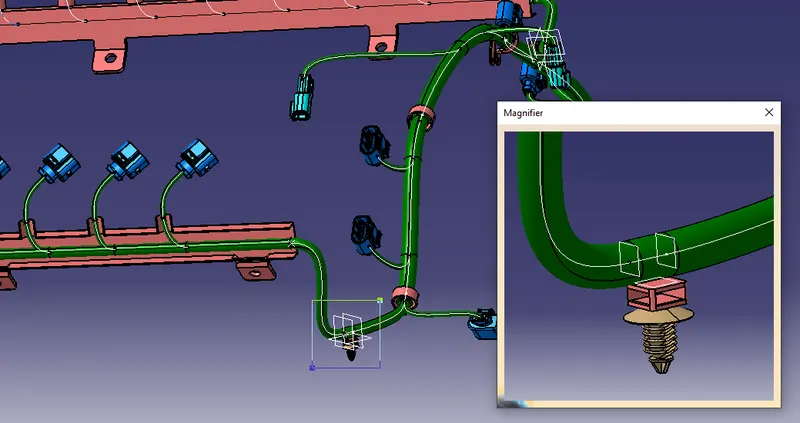
Offset management_ used to specify the values for clearence between surface or along the surface.
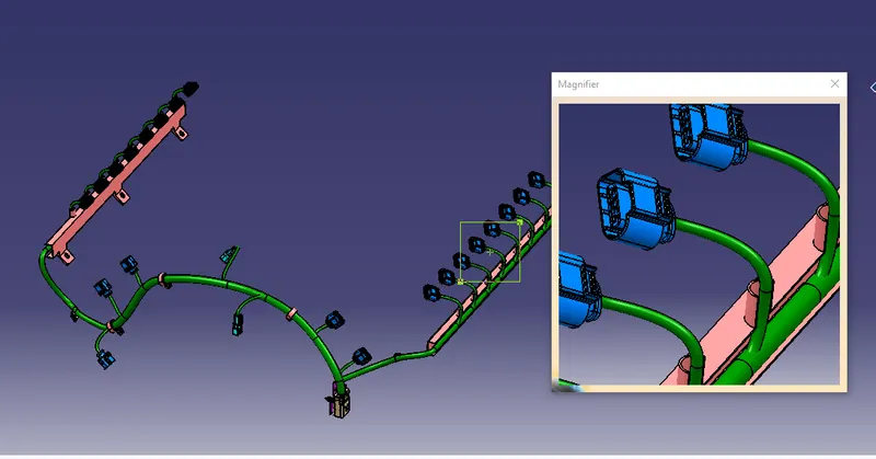
mostly used in external reference to avoid fauling of bundle with support plates or other mating parts.
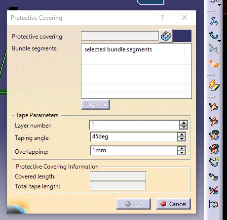
| PROTECTIVE COVERING |
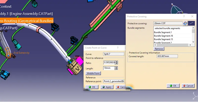
It's developed to protect the wiring bundles which are used in routing. As a protection cover which ensures safety of bundle from sharp edges, high temperature, dust and water. It can be selected by different factors such surrounding parts and environment. Moreover, It will be selected by either cotton or polymer and pvc.
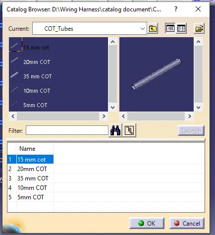
corrugated tubes,Convolutes, Sleeves and many other types of coverings are used to protect the wiring harness.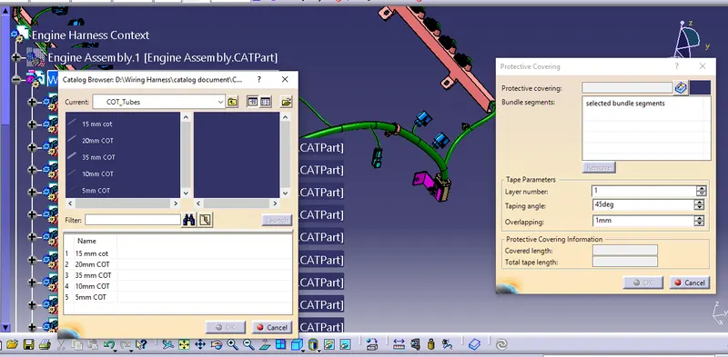
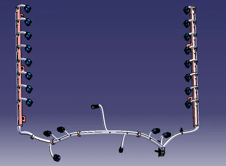
SILICA TUBES are used here to protect the bundles are stored in catalog.
| HARNESS CONTINUITY |
In this step, we must first ensure that multi-branch capability is selected before proceeding to Edit>Search>Advanced>Workbench-Electrical>Type-Bundle Segment>Attribute-Fully Connected.
Selecting 'True' displays all connected bundle segments while selecting 'False' displays all non-connected bundle segments.
In this case, we chose the 'True' option and searched for results. As shown in the figure below, all of the bundle segments are highlighted, indicating that they are all electrically connected.
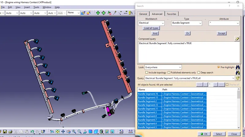
From above image, there was no disconnection between each segment and it can be used for flattening.
| RESULT |
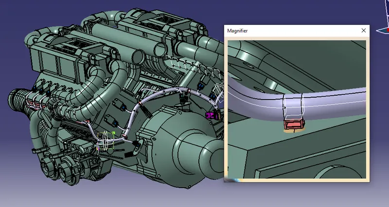
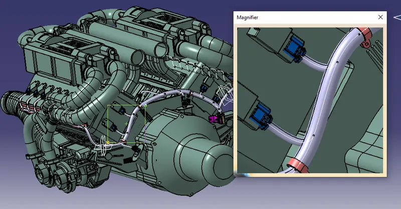
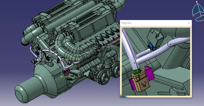
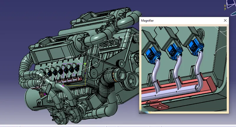
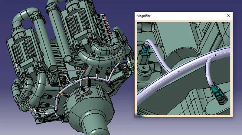
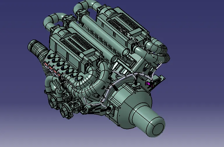
CONCLUSION,
THus the WIRING HARNESS for the given Engine Assembly has routed in Electrical workbench with considering design rules and criteria.