Project 1
Aim:-
Design a battery pack for a car roughly 150 Kw with 120 V. Use 3500 mAh 3.6V nominal NMC chemistry cell.
a. Design the battery pack configuration.
b. Draw the BMS topology for this battery pack.
Build a 3S2P battery pack configuration with generic battery block using Matlab/Simulink.
1. Design a battery pack for a car roughly 150 Kw with 120 V. Use 3500 mAh 3.6V nominal NMC chemistry cell.
a. Design the battery pack configuration.
b. Draw the BMS topology for this battery pack
Given Data:-
Voltage of Car = 120 V;
Power capacity = 150 Kw;
Nominal Voltage of cell = 3.6V;
Rated capacity of cell = 3.5 Ah;
a. Design the battery pack configuration.
No. of cells in series = Motor voltage / Nominal voltage
= 120 / 3.6
No. of cells in series = 33.33
No of cells in the parallel = Contineous current rating / cell nominal capacity
So to calculate the contineous current,
Power = Voltage * current
Current = Power / voltage
= 150*10^3 / 120
current = 1250 A
No of cells in the parallel = Contineous current rating / cell nominal capacity
= 1250 / 3.5
No of cells in the paralle = 357.14
so the battery pack configuration is 33S357P.
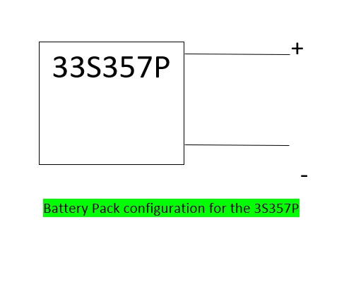
b. Draw the BMS topology for this battery pack.
Total Battery voltage = 120V
single battery voltage = 3.7v
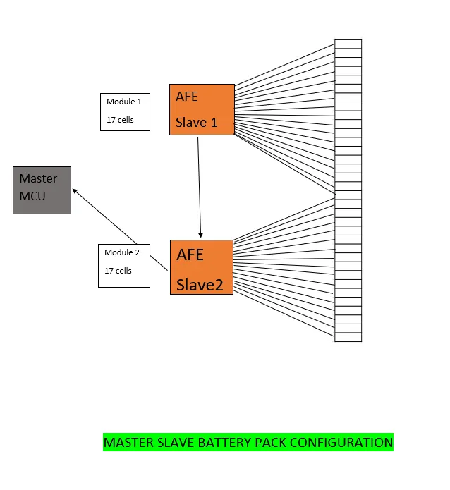
and in one AFE only 17 cells are used so we are using the master slave topology for the BMS.
17 cells in 1 AFE
17*3.6 = 61.2v
61.2 v in the 1 AFE,
61.2 * 2 = 122 v approx(120).
so here we have to used the 2 AFE and 34 cells.
Because in the cetrilized topology system we can't use more than 18 cells and in the module base topology is used for the storage system for more voltage , so here only master slave topology is left, so we used this topology.
BMS Topology archiecture:-
1)Centralised Topology;-
This Topology is used for only pack of 18 cells or less than 18 cells in a series only.
2)Master and Slave topology:-
This Topology is used for pack of 18 cells or greater than 18 cells in a series .
High Energy storage purpose or vehicle.
3)Modular Topology :-
This Topology is used for pack of 18 cells or grater than 18 cells in a series .
Large Energy storage purpose
4)Distributed Topology:-
This Topology is used for pack of 18 cells or grater than 18 cells in a series .
Very large Large Energy storage purpose
2. Build a 3S2P battery pack configuration with generic battery block using Matlab/Simulink.
Aim:-
The main aim is design a given battery pack configaration by using theMatlab/Simulink Tool.
Given data :-
Battery pack configartion = 3S2P
Simulink model :-
For creating the Simulink model battery pack configartion we are used following blocks:-
Lithium-ion Battery;
Controlled current Source;
Voltage Measurement;
Scope;
Display;
powergui;
constant block;
Procedure :-
Batteries in 3S2P configuration in Matlab/Simulink. That is 3 cells should be connected in series and 2 cells should be connected in parallel.
Total no of cell in the battery pack = No. of cells in series * No. of ceells in parallel
Then ,
Total number of cells in battery pack = No. of cells in series * No. of cells in parallel
= 3 * 2 = 6 cells
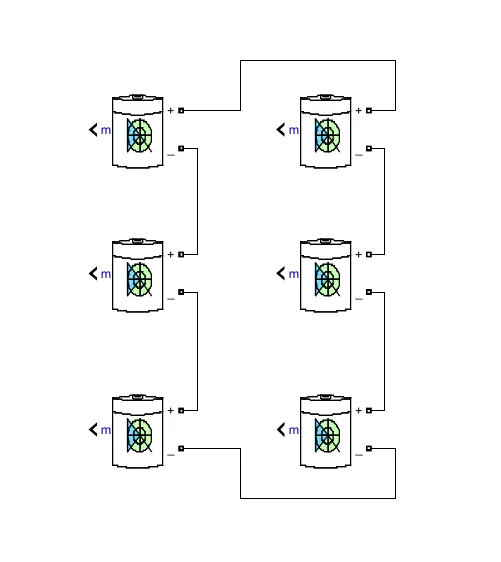
The figure 1 shows the arrangement of 6 cells.
We have to place total number of cells in battery pack (6 cells)
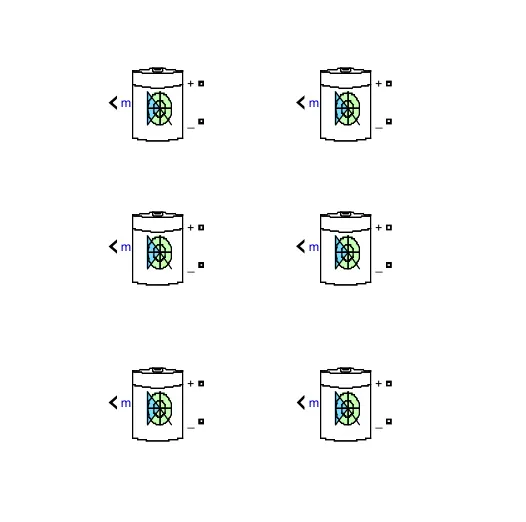
Step 2
Cells are connected in series
The series connection in the column 1 the first cell negative is connected to the positive of the second cell and second cell negative is connected to the third cell positive. Same connection for the column 2
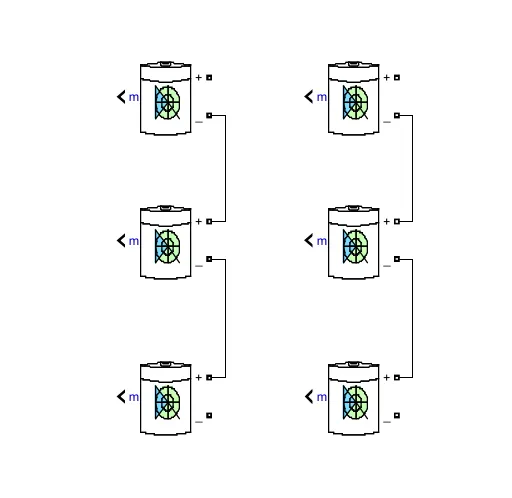
Step 3
cells are connected in parallel
After the series connection we made the paralle connection the 1st column first cell positive is connected to the 2nd column first first cell positive, and the last cell negative connection in the 1st column is connected to the 2nd column of last cell negative. Here our series and parallel connection is completed.
Model Explanation:-
The voltage measurement block is connected across the battery pack to measure the battery pack voltage. The scope output used for the battery pack consists of SOC (State of Charge), Current and voltage. The controlled current signal is given as the load to the battery pack. The constant blockis determined with battery capacity and it is given to the controlled current block.
The parameter given inside the battery is given below:-
- Nominal voltage of a cell 7.2V
- Rated capacity of a cell 5.4Ah
- Maximum voltage of a cell 8.3V
There fore ,
Nominal voltage of the battery pack = no.of cell in series * nominal voltage of a cell
= 3 * 7.2v
= 21.6 V
Rated capacity of the battery pack = no.of cell in parallel* rated capacity of a cell
= 2 * 5.4Ah
= 10.8Ah
The model is for an 21.6V 7 with 10.8Ah battery capacity
Overall voltage of the battery pack = maximum voltage of the battery * no. of cells in series
= 8.3V * 3
= 25 v
Overall voltage = 25 V
Simulink Battery Pack Module
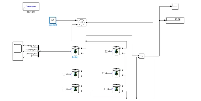
In this module after the series and parallel connetion of the cells we have connected the positive of the controlled current source is negative of the 2nd column last battery and negative of the controlled current source is connected to the positive of the 1st column of first battery. The output of this battery is connected to the bus selector and then it is cinnected to the scope. The constant block is connected to the input of the controlle current source and the voltage mesurement is connected in the parallel with the batttery module and the output of that is conneted to the scope and display, here we can see the result, and how much voltage is used.
Result:-
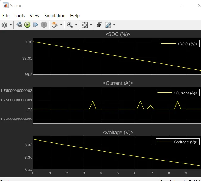
In the above we can see the result of the battery pack module in the result we can see the SOC%, Current and the voltage.
The SOC is almost 99.97%
Top Plot is (SOC%):-
The SOC (state of charge) is started to reduce from 100% to 99 % corresponding to the load given
Middle Plot (Current):-
The current signal is determined by the load and the decrease in current is due to regenerative braking.
Bottom Plot(Voltage):-
The voltage is around 8.3V. The increasing and decreasing voltage is with respect to the regenerative braking
From the above steps we have created the 3S2P battery pack configuration .