Project 1
1. First define all the connectors electrically which are used in this project.
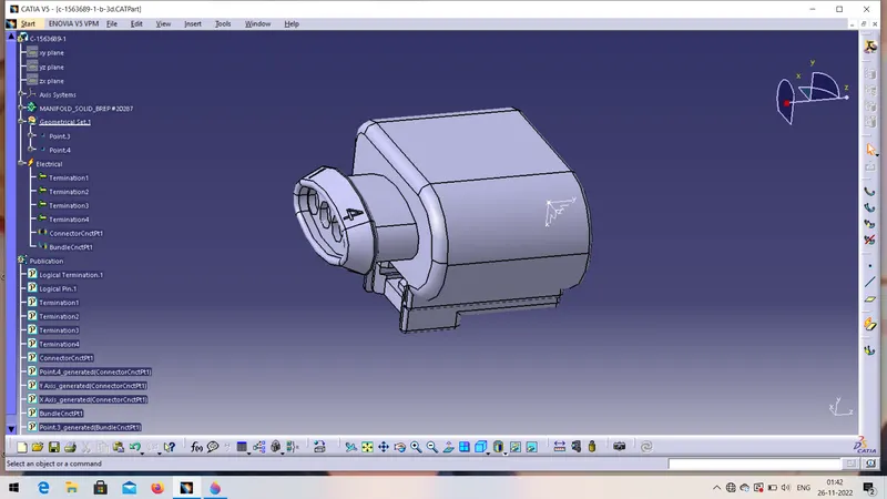
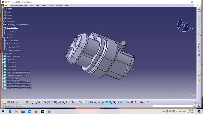
2. Download the CAD file of the connector and open it in part design workbench.
3. On the mating side of the connector create the points and axis having y-axis towards the locking direction.
4. Define connector electrically by changing the workbench as electrical part and click on "define connector " Command.
5. Then define connector connection point, bundle entry point for the same connector as well repeat the same process for remaining connector also.
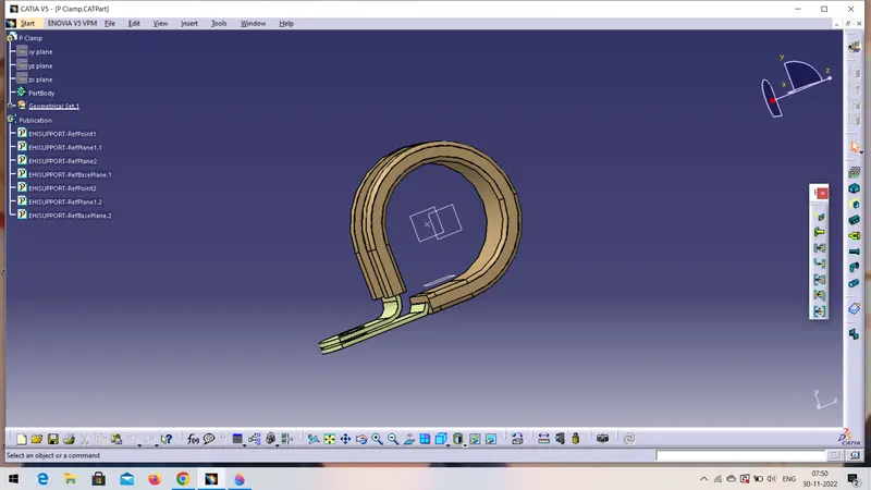
6. Now define the clamp as electric support.
7. First download the CAD file of p-clamps open it in part design workbench then add required points and plans ..
8. Change the workbench as electrical part design click on "define support" command and click on clamp..
9. Add bundle entry point and bundle exit point by using respective planes... Add twice.
10. Repeat the same process for all the clamps and clips as well.
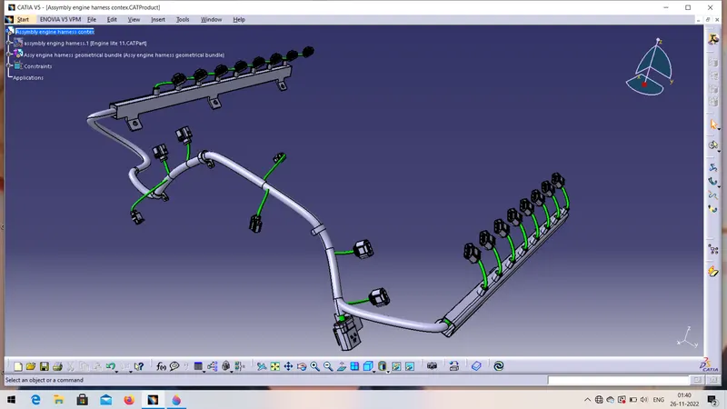
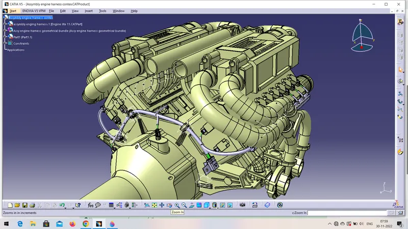
11. Now placed all the connector and clamps on the assembly and start routing of the wiring harness.
12. Create new product in which create new product add the contex assembly.
13. Add one more products name as electrical harness geometrical bundle.
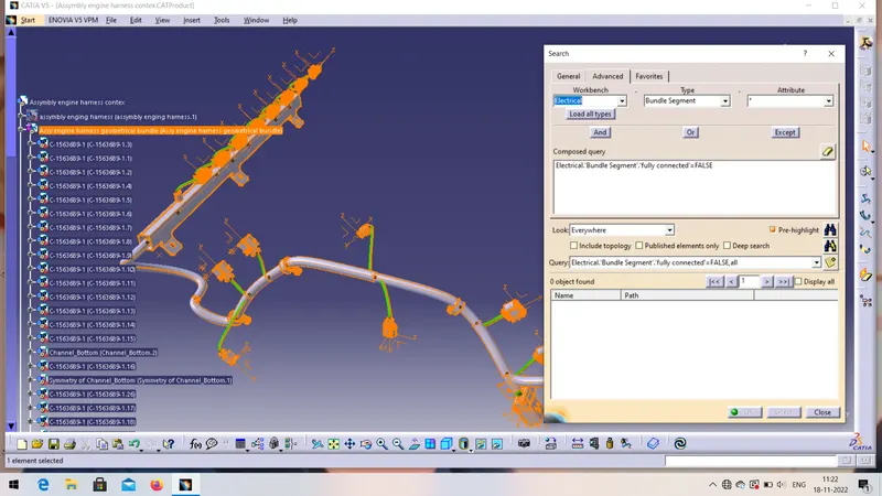
14. Now go to electrical wiring harness assembly workbench and select the geometric bundle command.
15. Now select multibranchable command and select interconnection connectorsconnectors and clamps to create the geometric bundle.
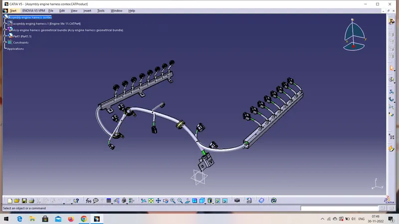
16. Similarly route the harness through different clamps and connectors and create the geometric bundlebundle also add necessary slack .
17. Check the bundle continuty as the geometric bundle are fully connected or not.
18 . Now add protection covering.
19. In electrical part design create the new part select the protective covering command and click on the part name on the tree and give specific name (i.e, cot_10mm)
20. now create catlogue by click on new catlogue, by selecting condut in the family, save it.
21. now click on protective covering command , select the proper diameter of the cot tubes from the catlogue box and add on the branch.
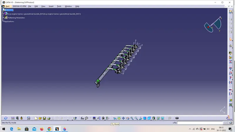
22. Flattening of the Harness.
23. Go to wiring harness flattining workbench give the flattening parameters.
24. select extract command and select geometrical bundle.
25. .EHF extension will added to the geometrical bundle assembly.
26. now click on flattening command and do flattening.
27. now make one more new file for drawing.
28. go to the draingfile add front view of any face or plane the drawing will be added to drawing sheet.