Preparing Schedule & Cost Estimation for a building using REVIT
1) Use the shortcut keys in Revit discussed in class to complete the following tasks and list them below
a. Using 3D model create a section box
b. To create similar doors and windows in a floor plan layout
c. To reduce the thickness of lines visible in plan views
d. To apply override settings to a floor in the model section view
e. To increase the range of visibility in a plan view
f. To select the previously selected items
g. To add annotations to the model views
h. To bring the model elements in line
i. To rotate the model elements
j. To move an object to another location
k. To copy a model element
l. To mirror an element about an axis
m. To create an array of model elements
Aim : To use shortcut keys and complete the following tasks.
- Using 3D model create a section box
b. To create similar doors and windows in a floor plan layout
c. To reduce the thickness of lines visible in plan views
d. To apply override settings to a floor in the model section view
e. To increase the range of visibility in a plan view
f. To select the previously selected items
g. To add annotations to the model views
h. To bring the model elements in line
i. To rotate the model elements
j. To move an object to another location
k. To copy a model element
l. To mirror an element about an axis
m. To create an array of model elements
Introduction
Shortcut keys used in Revit for performing given task are as follows:
- Section box – BX
- Create similar – CS
- Thin lines – TL
- Override setting to floor – VG
- View range – VR
- Reselect – Ctrl + left key
- Annotation – DI
- Align – AL
- Rotate – RO
- Copy – CO
- Move – MV
- Mirror – MM
- Array - AR
Procedure
Step 1
- Open the Revit software and open week 7 3D model view.
Step 2
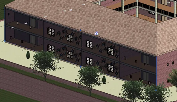
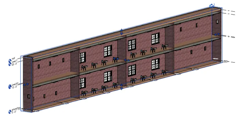
- Select the wall and type BX it will create the section box as shown below.
Step 3
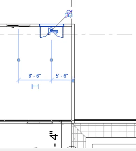
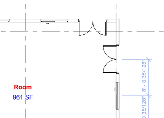
- Open the floor plan view select the door and type CS and place the door at required position as shown below.
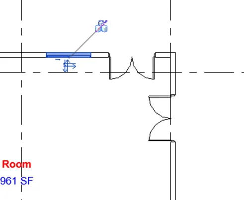
- Similarly select the window and type CS it will generate the similar window like which is selected as shown below.
Step 4
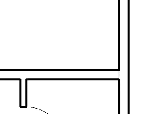
- Original thickness of line in the project is shown below.
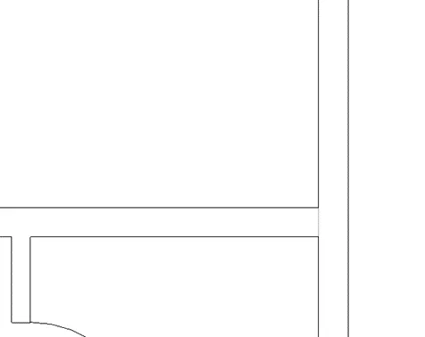
- Type TL it will change the thickness of line visible in floor plan is shown below.
Step 5
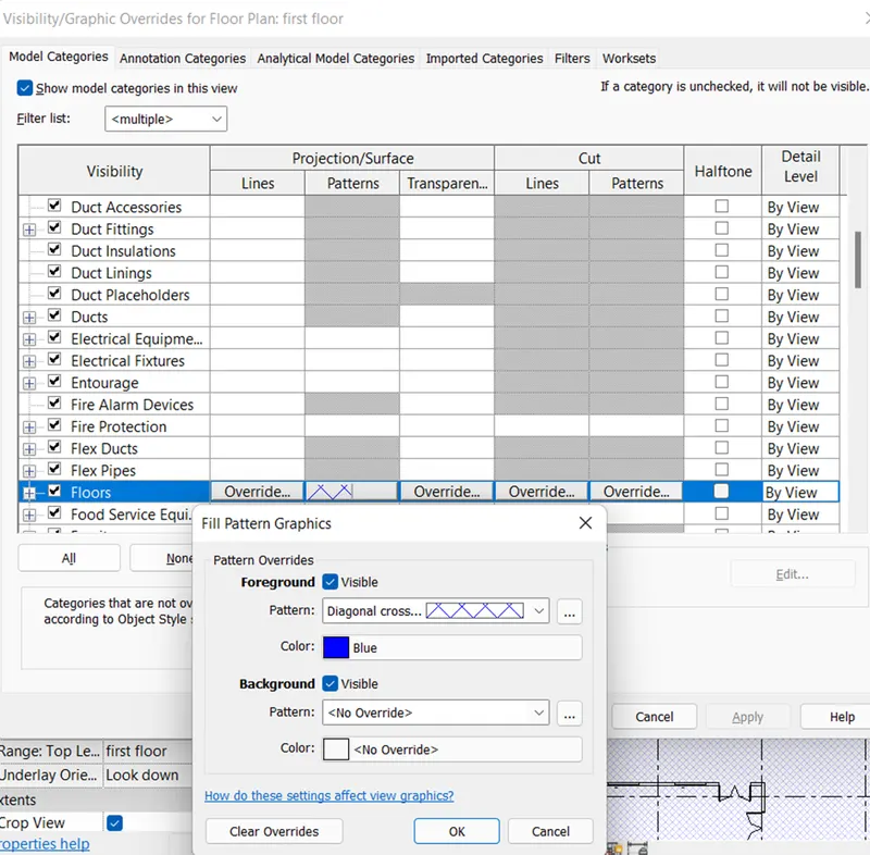
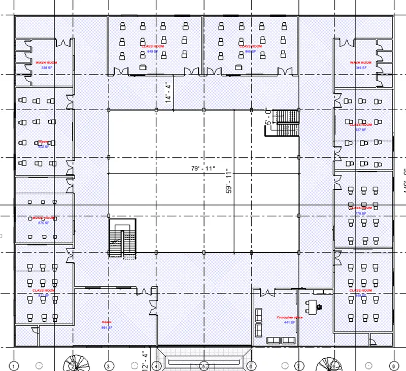
- Open the floor plan and type VG to open the visibility setting dialog box, select the floor option from dialog box and change the overrides for pattern and apply the color to the pattern as shown below using fill pattern dialog box and select apply and ok from visibility graphics dialog box.
Step 6
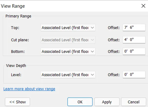
- To change the range of visibility type VR and change the setting as per requirement from view range dialog box as sown below.
Step 7
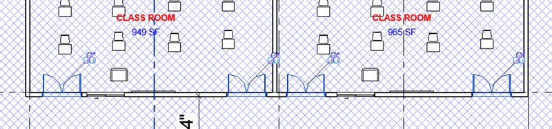
- Select the multiple door and unselect it.
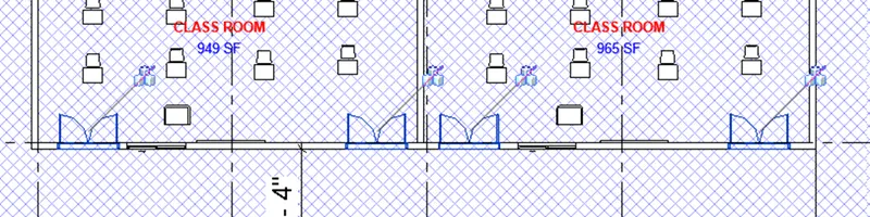
- Type control + left key to reselect the previously selected units so that it will select in one go as.
Step 8
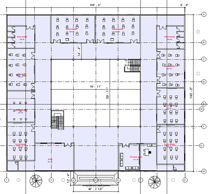
- For adding the annotations to the model view type DI it will open the annotation cursor and give annotations to the view as shown below.
Step 9
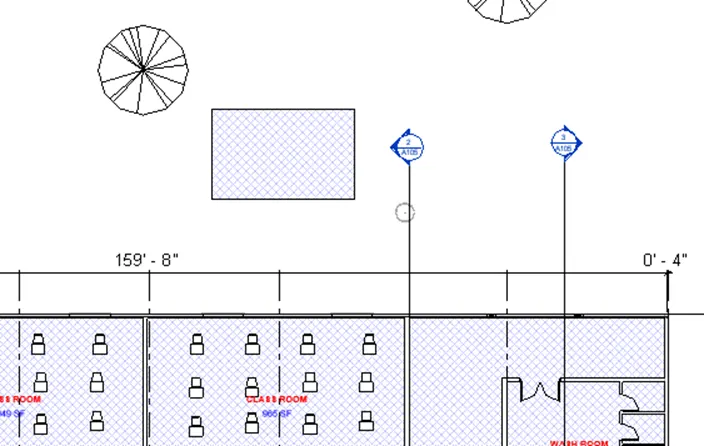
- To use the align tool, draw the random floor outside the model, as shown below.
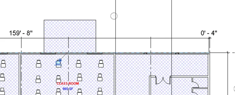
- The type AL, select the wall along which floor needs to be aligned and then select the floor edge which is to be aligned then floor gets aligned as shown below.
Step 10
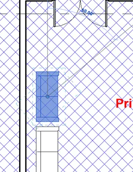
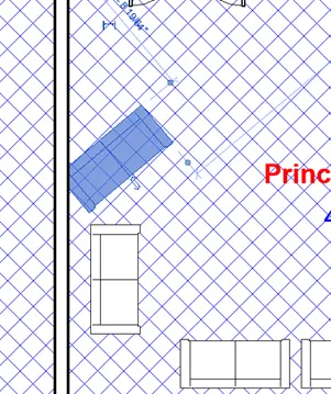
- To rotate the component using shortcut key, select the component, type RO it will open the reference line the rotate the component at the desired angle as shown below.
Step 11
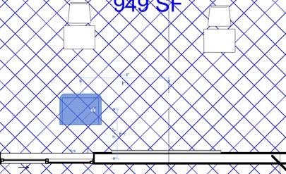
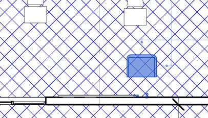
- To move the element to another position, select the element and type MV then move the element using move cursor at required position as shown below.
Step 12
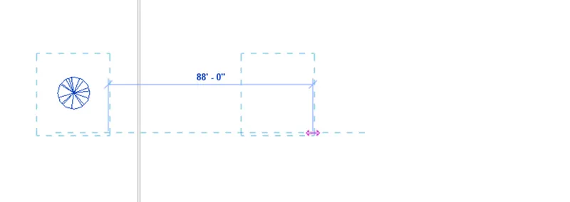
- Select the component which is required to be copied, type CO and copy the component at the required position as shown below.
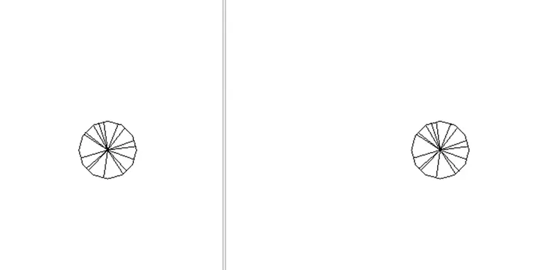
Step 13
- To mirror an element, select the element, type MM, select the axis about which element need to be mirrored then it will create the mirror image as shown below.
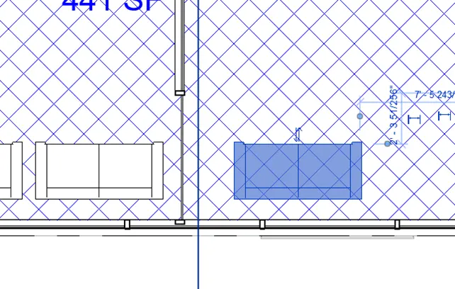
Step 14
- To crate the array of the modelled element, select the element, type AR type number of element as 4, press enter and specify the required center to center distance using cursor to create array as shown below.


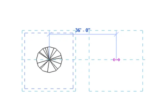
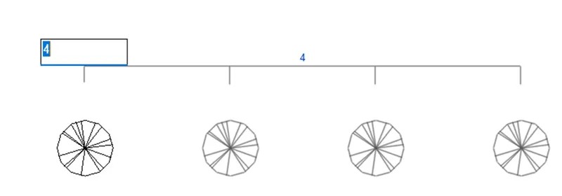
- Therefore, created array of the element is shown below.
Result :
Therefore, all the shortcut keys in Revit are discussed and all the given tasks are completed using the respective shortcut key as shown above.
2) Using Revit and the project used from week 6 to 8 prepare a schedule for the following
a. Walls
b. Doors
c. Windows
d. Material – Concrete/Wood
Aim : To prepare schedules for walls, doors, windows and material- concrete or wood using Revit software.
Introduction :
- Schedule is a tabular display of the information, extracted from properties of the elements in a project.
- Revit is Building information software, where we can prepare the component schedule where we can get the details of all the component which is helpful for various purposes like cost estimation, quality estimation etc.
- Schedules can be prepared by using the schedule tool of view tab from create panel.
Procedure :
Step 1
- Open the week 7 challenge file from the Revit software to create the schedules.
Step 2 : Preparation of wall schedule
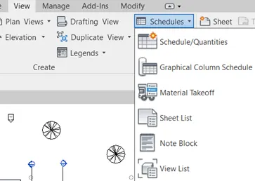
- For preparing the schedules go to view tab, select the schedule option from crate panel and then select the schedules quantities from the list.
Step 3
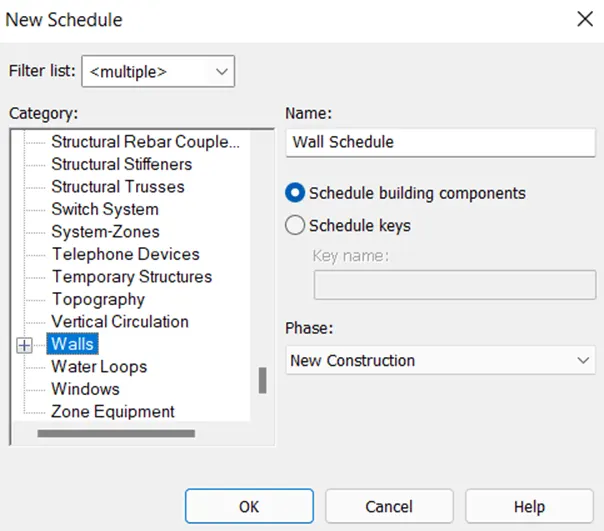
- Select the wall option from the list to prepare wall schedule and select ok.
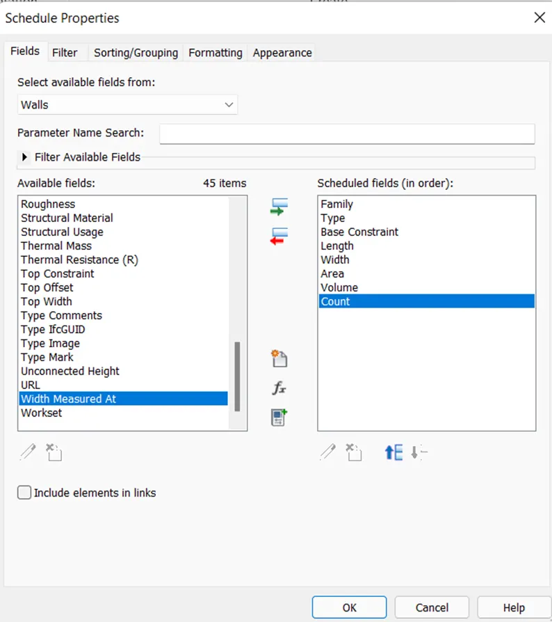
- Add the schedule properties as shown below in the schedule properties dialog box and select ok.
- The wall schedule is shown below.
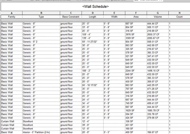
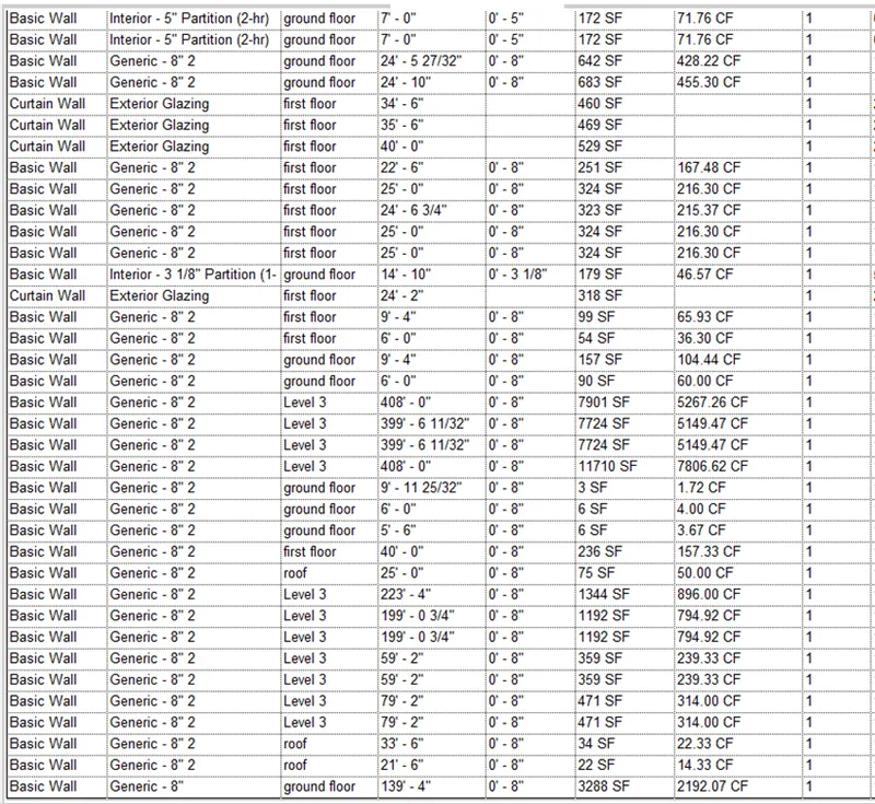
Step 4
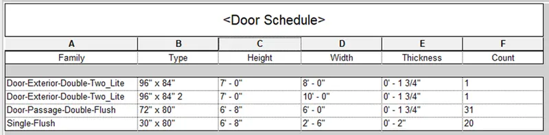
- For creating the door schedule, again, go to view tab and select schedule quantity.
- Select the door from new schedule dialog box, select ok and add the desired properties in the schedule using schedule properties dialog box as shown below.
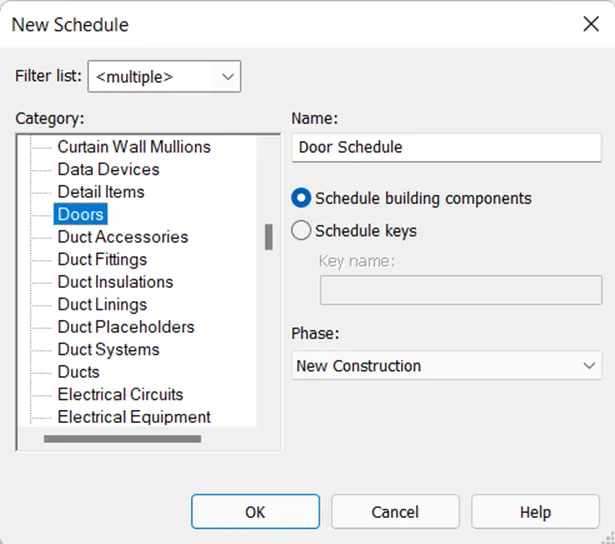
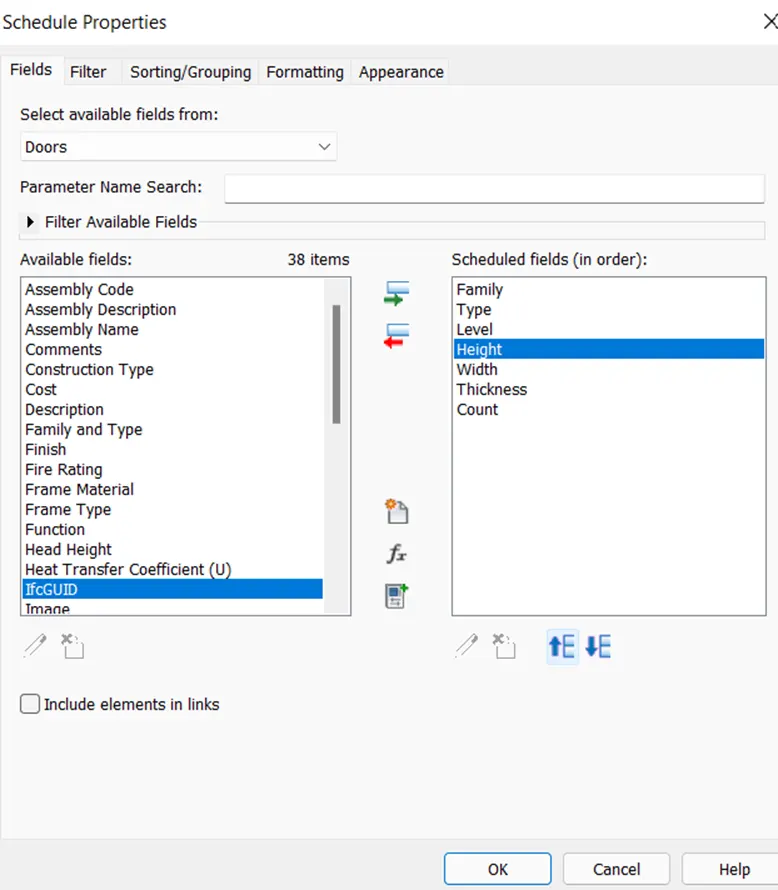
- The door schedule is shown below.
Step 5
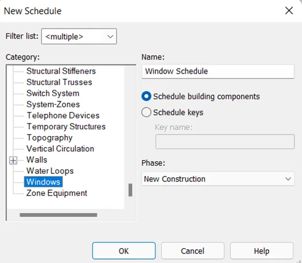
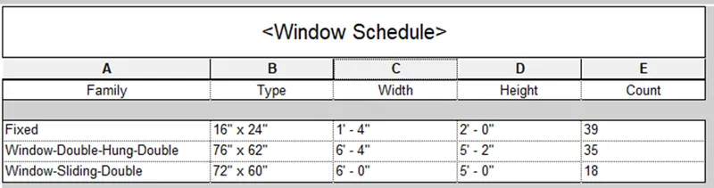
- For creating the window schedule, again, go to view tab and select schedule quantity.
- Select the window from new schedule dialog box, select ok and add the desired properties in the schedule using schedule properties dialog box as shown below.

Step 6
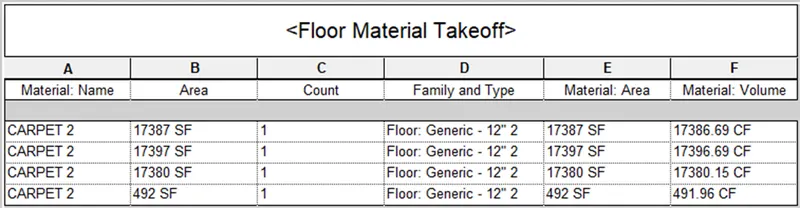
- To create floor material takeoff, go to schedule option of view tab, select material takeoff option and select the floor material from list.
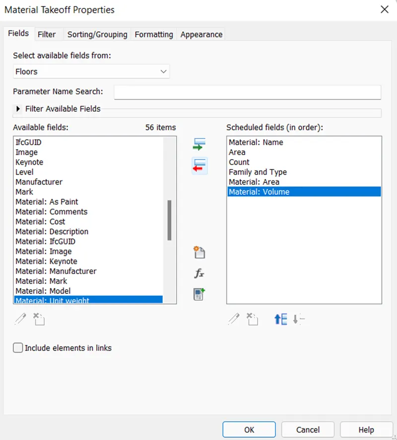
- Then add material takeoff properties and select ok from material takeoff properties dialog box.
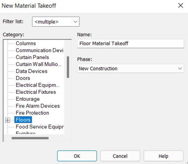
- The created floor material takeoff schedule is shown below.
Result :
Therefore, using the Revit the schedules for week 6 to 8 project are prepared as shown below.
Wall schedule
Door schedule
Window schedule
Floor material takeoff schedule
3) Using Revit Calculate area and volume of each room in the model with appropriate room tags applied to each room. Prepare a schedule report for area and volume of each room.
Aim : To calculate area and volume of each room in the model with room tags and prepare the schedule report for area and volume of each room.
Introduction :
- Using the schedule tool of the view tab we can prepare the room schedule where we can list the area and volume or any other room parameters.
- We can identify the rooms with the name of room tags.
- Room schedule acts as document which provides tabular display of the information about the rooms.
Procedure :
Step 1
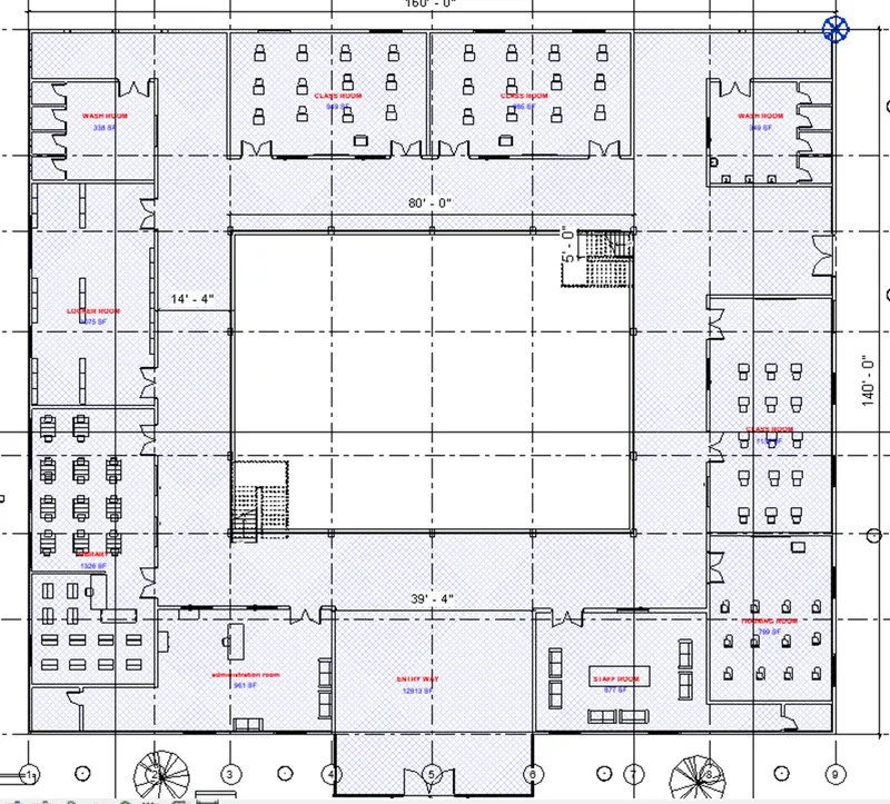
- Open the project file in the Revit software, go to architecture tab, select the room from room and area panel and add the room tags to each room and assign them appropriate name as shown below.
Step 2
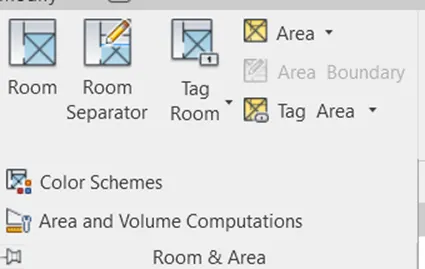
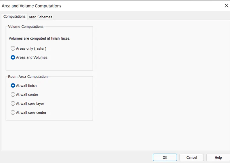
- For calculating the area and volume select the drop down of room and area pane of architecture tab and select area and volume from area and volume computation dialog box and select ok.
Step 3
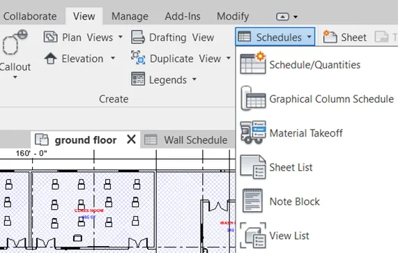
- Go to view tab select the schedule option from create panel and select schedules /quantities from list.
Step 4
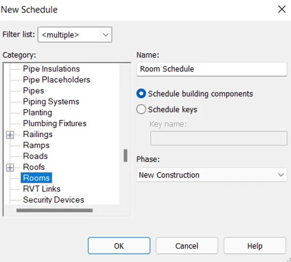
- Select the room from new schedule dialog box list and select ok.
Step 5
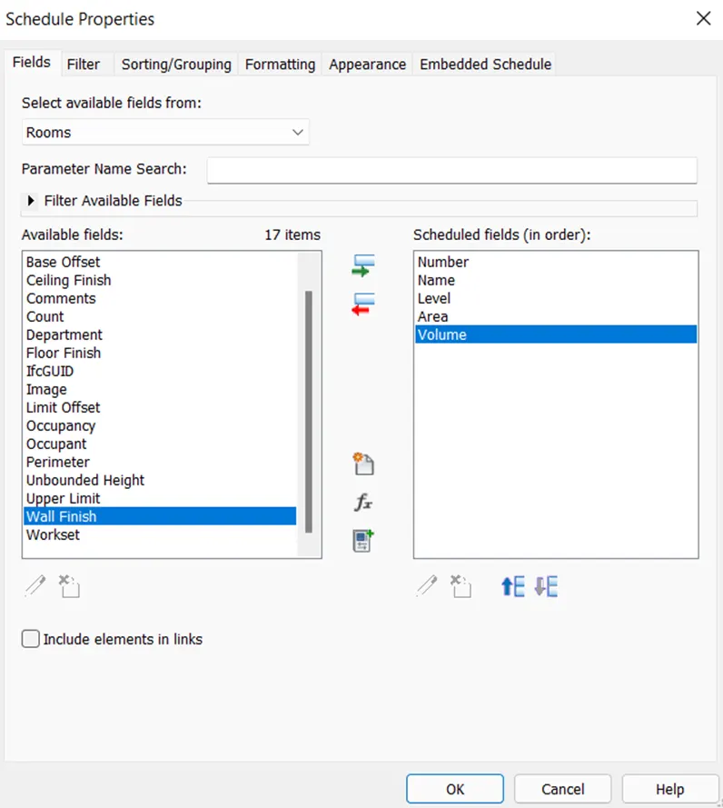
- Then add the appropriate schedule properties from the schedule properties dialog box and select ok.
Step 6
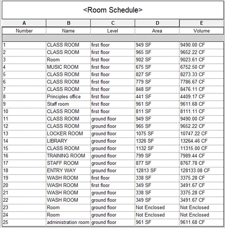
- The schedule for rooms is shown below.
Result :
Therefore, area and volume of each room is calculated and schedule report for area and volume of each room is created using Revit software as shown below.
4) Using the same schedule using the unit cost rate for materials available in the internet, prepare total cost of materials used in the project
a. Total Cost of Materials
b. Individual Material Take off
Aim : To prepare schedules for total cost of materials using unit cost rate and individual material take off using the Revit software.
Introduction
- Material takeoff schedules list the sub-components or materials of any Revit family.
- Revit is BIM software where we can prepare cost estimation by assigning the unit costs to the individual materials or families and then compute the total cost.
- We can estimate the total cost by using different settings from the schedule tool.
Procedure
Step 1
- Open the Revit software, and open the week 7 project.
Step 2
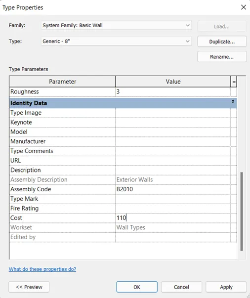
- Select the wall from the model and select edit type from properties window of the Revit.
- Put the cost of wall as Rs. 110 per sq. feet, select apply and ok.
Step 3
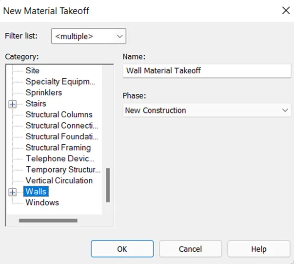
- Go to view tab and select the schedule tool followed by selection of material takeoff, select the walls from new material dialog box, and select ok.
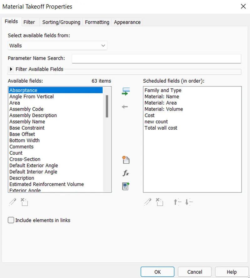
- Now select the required properties of the wall to add in the schedule and select ok.
Step 4
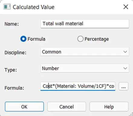
- Now select the formula option from material takeoff properties dialog box and add the formula as shown below.
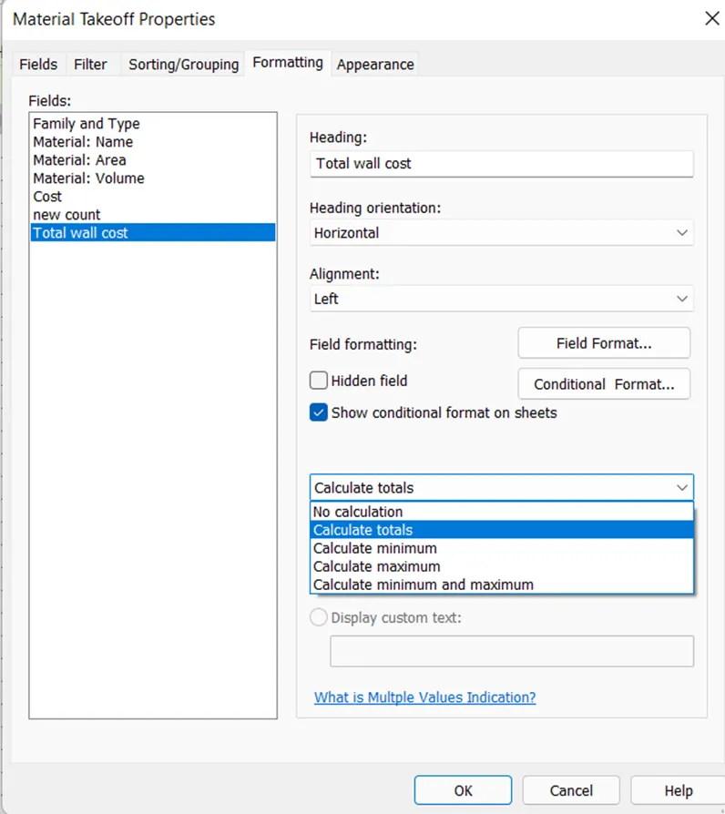
- Then go to formatting and select total cost from fields and select calculate totals as shown below.
Step 5
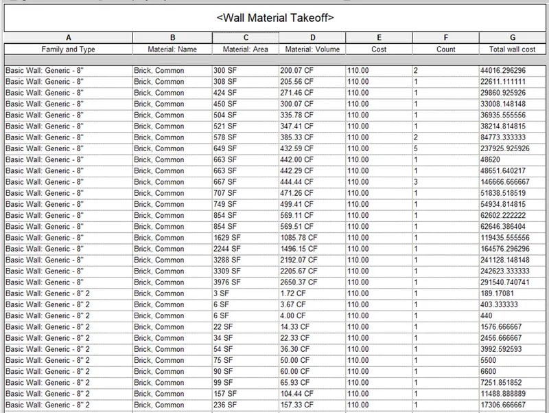
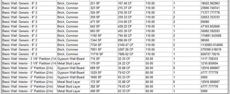
- Therefore wall material takeoff is created and is shown below.
Step 6
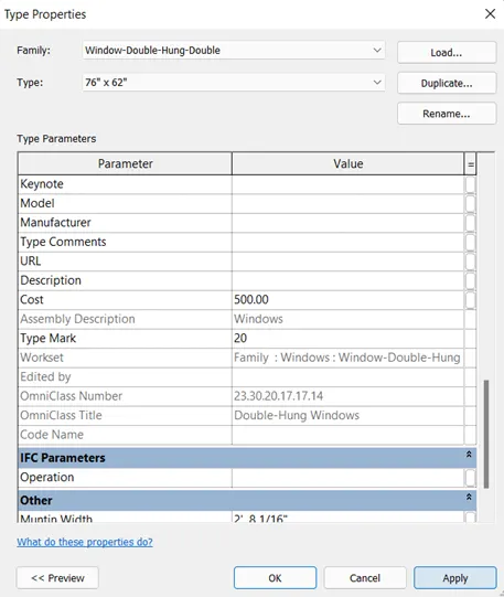
- Now select the window and add the cost of window using the edit type option of the properties window as shown below.
Step 7
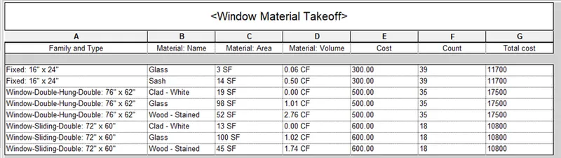
- Similarly create the material takeoff schedule for window using schedule tool of the view tab by adding the required properties using properties dialog box.
Step 8
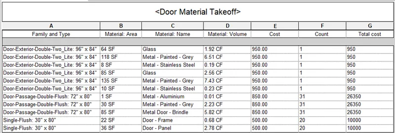
- To create door material takeoff, select one of the door from model and add the cost to the door using edit type of properties window.
- Now, select the schedule tool from view tab and select material takeoff.
- Select the door from list from the create new schedule dialog box and add the required properties in schedule using schedule properties dialog box.
Step 9
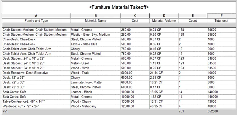
- For creating furniture material takeoff, select all of the furniture component from model and add the cost to the component using edit type of properties window.
- Now, select the schedule tool from view tab and select material takeoff.
- Select the furniture from list from the create new schedule dialog box and add the required properties in schedule using schedule properties dialog box.
Result :
Therefore, schedule of total cost of materials as well as individual cost of materials is prepared using Revit software as shown below.
Wall material takeoff
Window material takeoff
Door material takeoff
Furniture material takeoff
5) Using the concept of Visual Programming discussed in class, list a flowchart for the following scenario
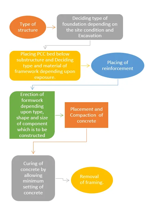
a. How to decide framings for a structure using Dynamo ?
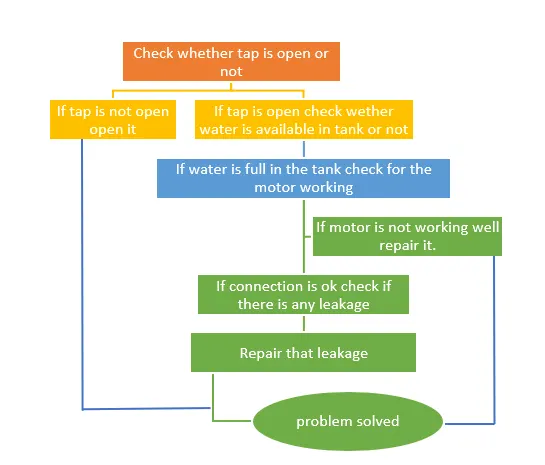
b. If there is no water coming from the pipes
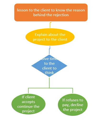
c. If request for money from client has been declined for the project
Aim : To list the flowchart for
- Deciding framings for a structure using dynamo
- If there is no water comping from pipes
- If request for money from client has been declined for the project
Introduction :
- In visual programming program is written in the form of flowchart.
- Dynamo is visual programming tool that works with Revit.
- With dynamo we create programs by manipulating graphic elements called as nodes.
Procedure :
Step 1
Flowchart for Deciding framing for a structure using Dynamo
Step 2
Flowchart If no water is coming from pipe
Step 3
Flowchart If request for money from client has been declined for the project
Result :
Flowchart for deciding framings for structure using dynamo, if there is no water coming from pipe and if request for money from client has been declined for the project is shown below.
6) List the parameters associated with each model element
a. Wall
b. Floor
c. Door
d. Window
e. Table
f. Building
Aim : To list the parameters associated with each model element in the Revit.
Introduction :
- Parameters refers to the characteristics that are used to define a given model.
- Every model in the Revit is associated with certain parameters which describes the properties of that model.
Procedure
Step 1
Wall parameters
- Wall type
- Wall length
- Wall thickness
- Wall height
- Location line
- Base constrains
- Heat transfer coefficient
- Thermal resistance of wall
- Absorptance of wall
- Top constrains
- Wall function
Floor parameters
- Floor type
- Floor thickness
- Floor level
- Height offset
- Slope of floor
- Perimeter of floor
- Area of floor
- Floor volume
- Elevation at top
- Elevation at bottom
Door parameters
- Door type
- Door function
- Frame material
- Door width
- Door height
- Door thickness
- Strike height
- Door panel material
- Door handle material
Window parameters
- Window width
- Window height
- Head height
- Sill height
- Window rough width
- Window rough height
- Exterior Frame material
- Interior frame material
- Glass panel material
Table parameters
- Table material
- Table type
- Default elevation
- Assembly code
- Cost
- Table height
- Table type
- Table width
Building parameters
- Building type
- Building area
- Building function
- Building height
- Design loads
- Building location
Result :
Therefore, parameters associated with each Revit model is listed as shown above.