Preparing Schedule & Cost Estimation for a building using REVIT
1) Use the shortcut keys in Revit discussed in class to complete the following tasks and list them below
a. Using 3D model create a section box
b. To create similar doors and windows in a floor plan layout
c. To reduce the thickness of lines visible in plan views
d. To apply override settings to a floor in the model section view
e. To increase the range of visibility in a plan view
f. To select the previously selected items
g. To add annotations to the model views
h. To bring the model elements in line
i. To rotate the model elements
j. To move an object to another location
k. To copy a model element
l. To mirror an element about an axis
m. To create an array of model elements
Ans 1.
INTRODUCTION: Use of Shortcut keys in Revit modelling
AIM: To use various short cuts in Revit to complete the given tasks in the question.
PROCEDURE:
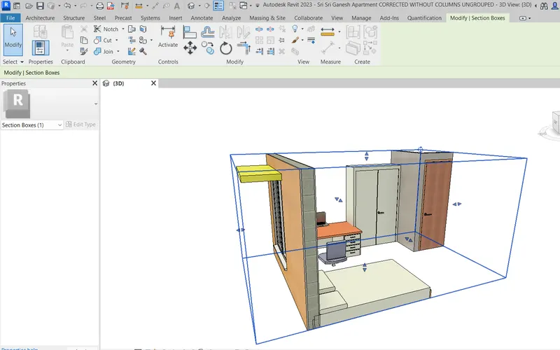
a. Using 3D model create a section box
- Open any model created in Revit.
- To create section box, select the elements or entire model for which the section box is to be created
- Then enter shortcut key BX for Section box
- The section box is created around the selected elements or model with the shortcut key BX
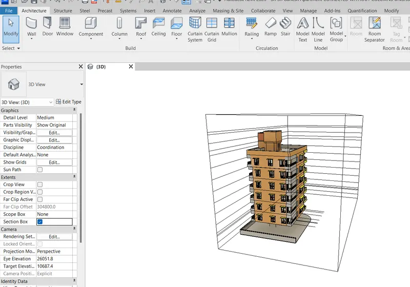
- The section box for selected element (window) is created using BX short cut key
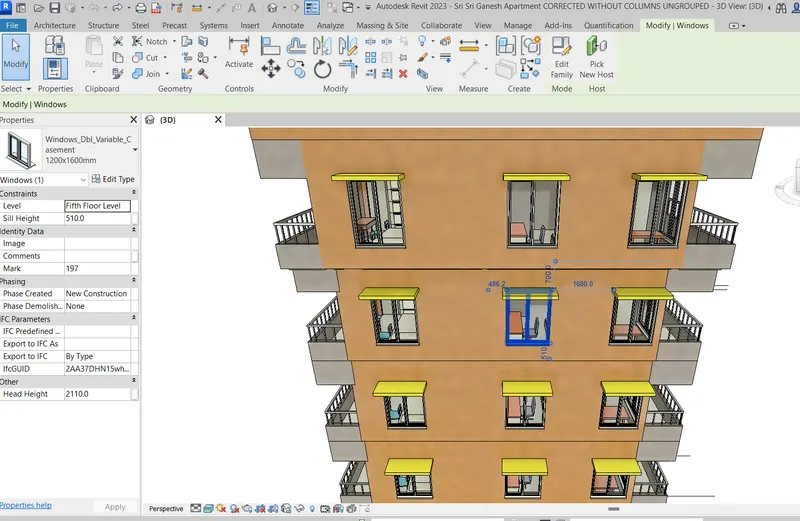
- The section box is created around the selected element with the shortcut key BX
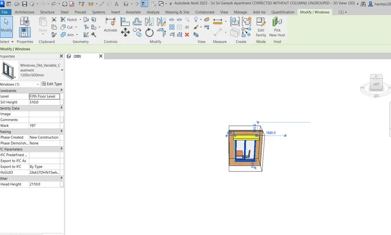
- The section box is can be adjusted to increase or decrease required view
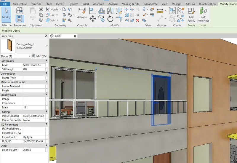
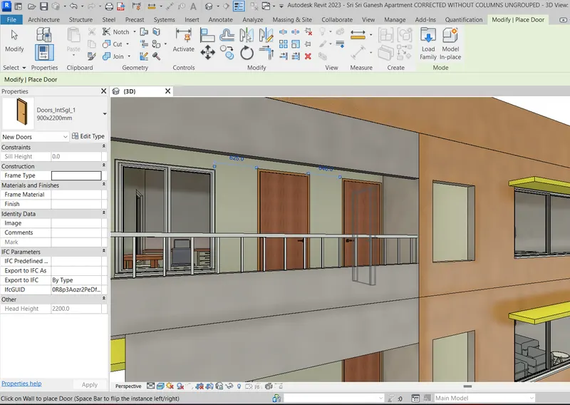
b. To create similar doors and windows in a floor plan layout
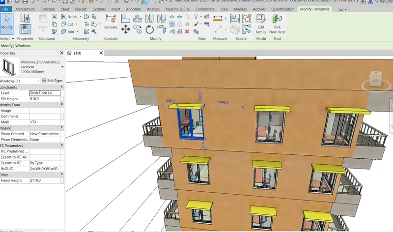
- In the model select the window for which similar window is to be created
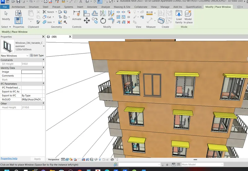
- Enter shortcut key CS to create similar window element and place the created similar window on the required location
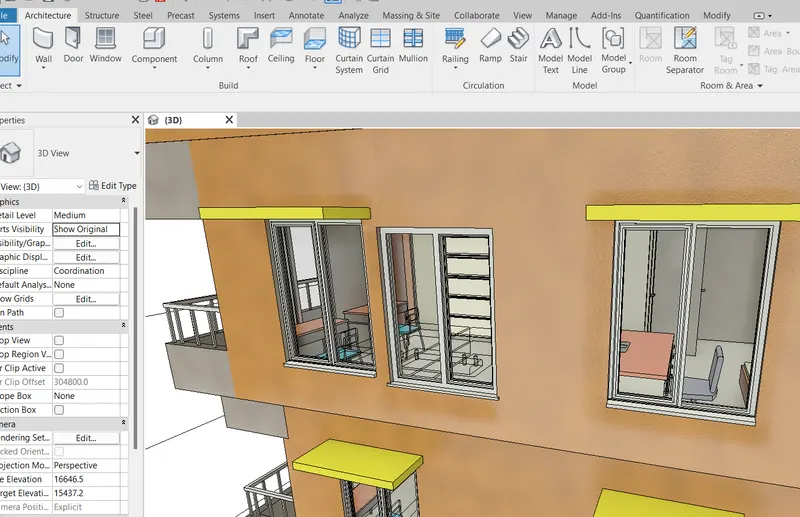
- Similarly select the door for creating similar door
- Enter shortcut key CS to create similar door element and place at required location
- The element can be flipped by pressing Space bar.
c. To reduce the thickness of lines visible in plan views
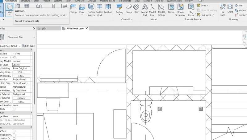
- Open a plan view
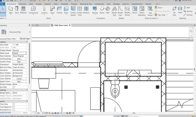
- Enter shortcut key TL to change the thickness of the lines in the view
- By TL shortcut key the line thickness can be changed
- The lines are thin lines in the below screeenshot
- The lines are changed to thick lines by TL shortcut key shown in below screenshot.
d. To apply override settings to a floor in the model section view
- Open a plan view
- Select the floor
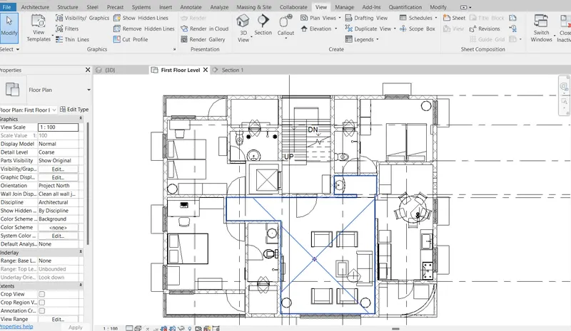
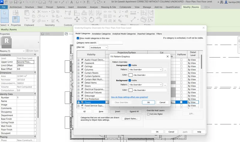
- Enter VG shortcut key for visibility graphics
- Select the floor overrides to change the floor pattern or colour in Fill graphics window.
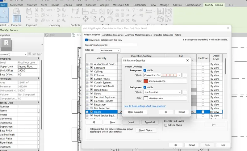
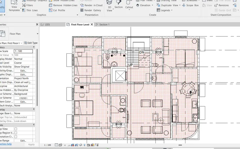
- The selected pattern and colour are seen in the below screenshot
e. To increase the range of visibility in a plan view
- Open a plan view
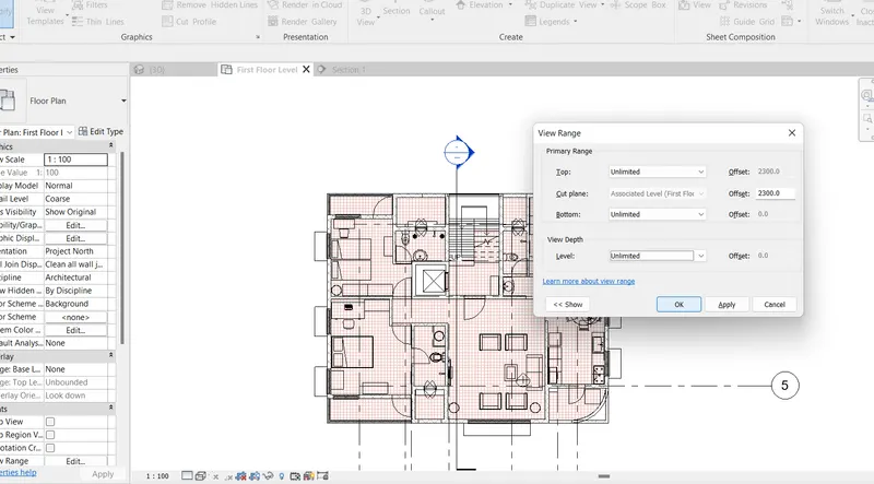
- Enter VR shortcut to open the View Range of the plan
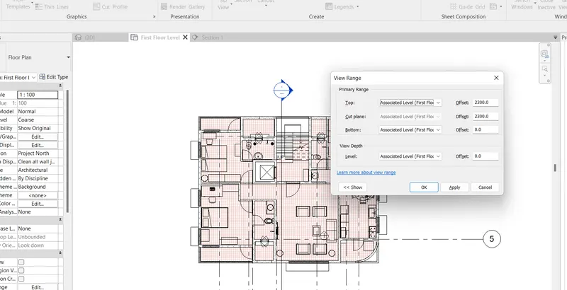
- Edit the required range for the plan view and click OK
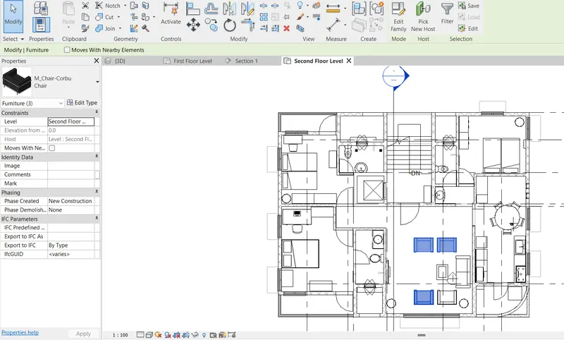
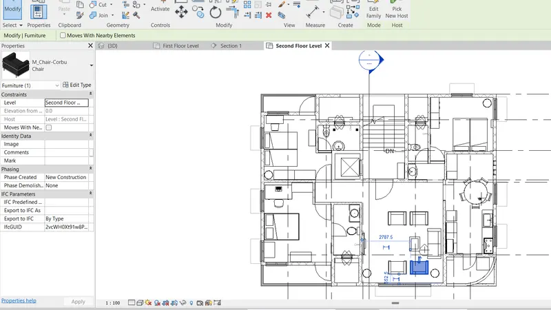
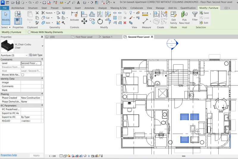
f. To select the previously selected items
- In the drawing to open the previously selected items Press Ctrl < shortcut key
- The previously selected item/items will be opened
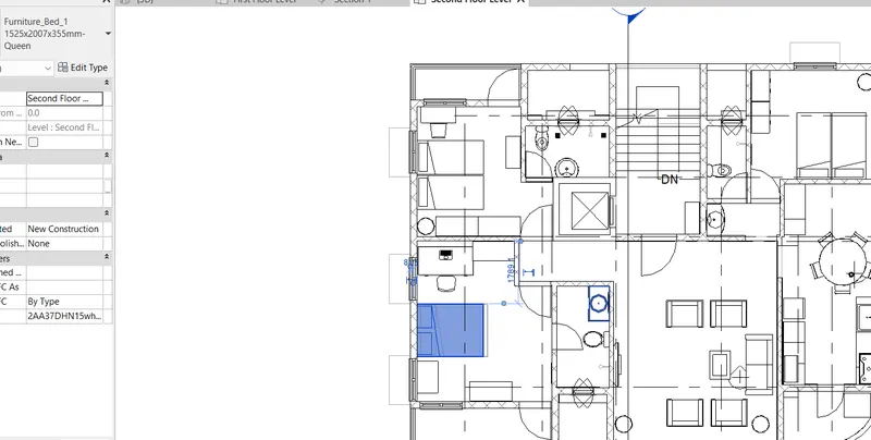
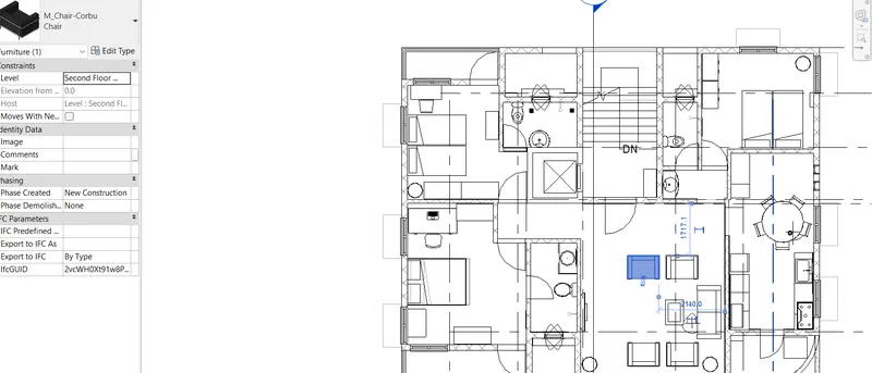
- If multiple selection is done previously and was missed during selecting the element then by CTRL < key the previous multiple selection can be viewed as shown below.
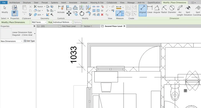
g. To add annotations to the model views
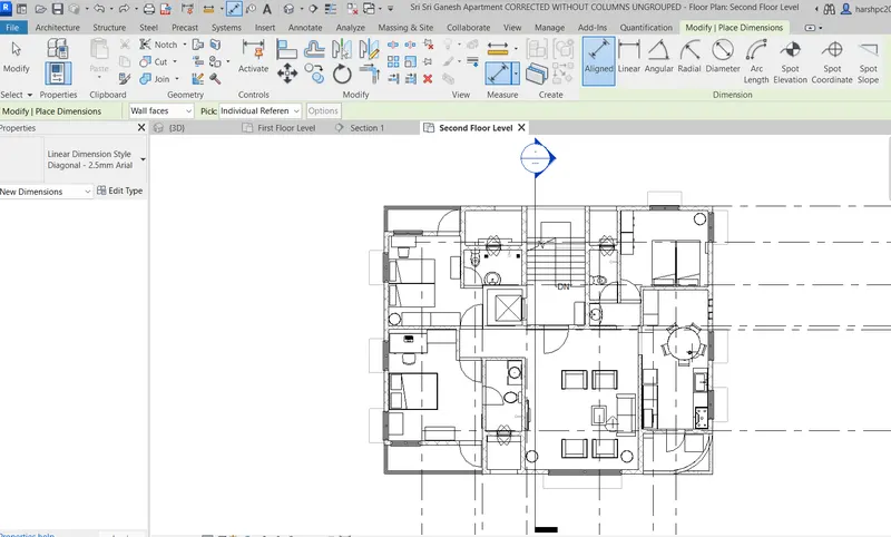
- To add annotations to model view, enter Di shortcut key
- The annotation ribbon will be opened
- Annotations like dimensions etc. can be provided
h. To bring the model elements in line
- To bring the model elements in line, enter AL shortcut key to align the elements
- The align icon will appear near cursor
- Select the baseline of one element for aligning
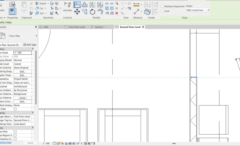
- Then click on the other element line to align with the first element
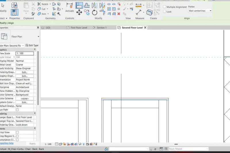
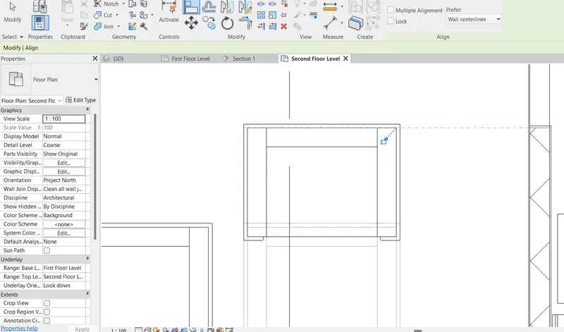
- The elements get aligned as shown below in screenshot
i. To rotate the model elements
- In the model select the element to be rotated
- Enter the RO shortcut key for Rotation
- The Rotation icon will appear and the rotation tab will be selected
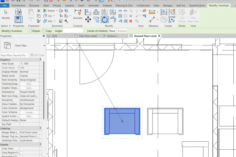
- Enter the degree of rotation and press Enter key
- The element will be rotated
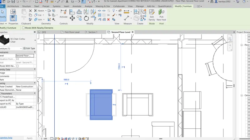
j. To move an object to another location
- Select the element in the model to be moved
- Then enter MO shortcut key to Move the element
- The move icon will appear on cursor
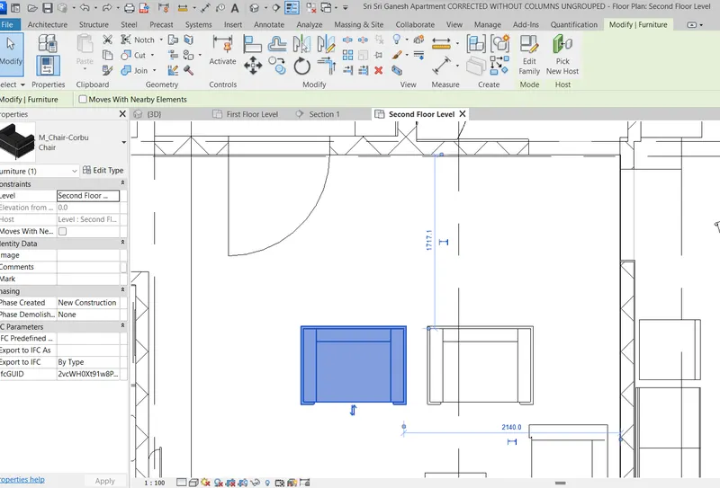
- Move the element to required position
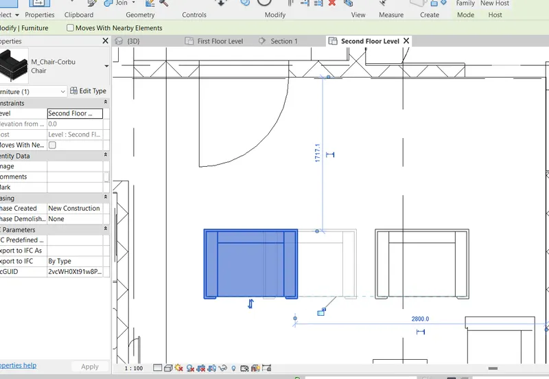
k. To copy a model element
- Select the element in the model to be copied
- Then enter CO shortcut key to Copy the element
- The Copy tab will be selected and move icon will appear on cursor
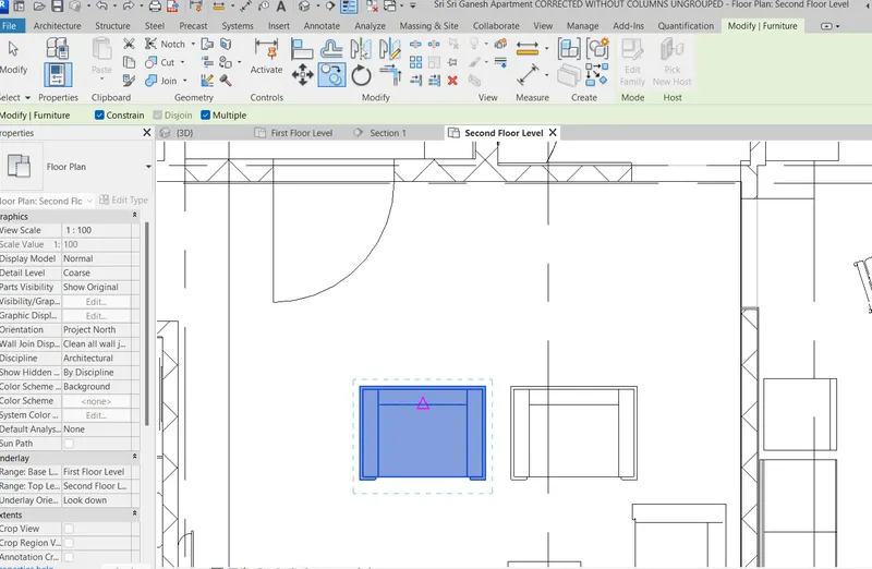
- Move the element to required position and the element will be copied to new location
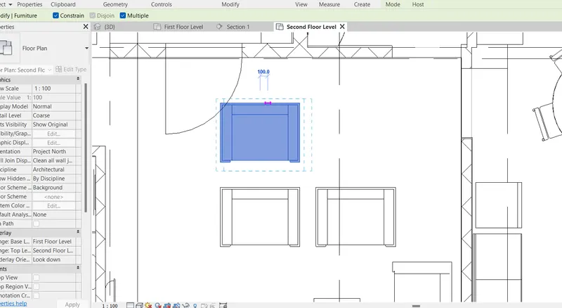
l. To mirror an element about an axis
- Select the element in the model to be mirrored
- Then enter MM shortcut key to Mirror the element by picking axis
- The Mirror tab will be selected accordingly and the icon will appear on the cursor
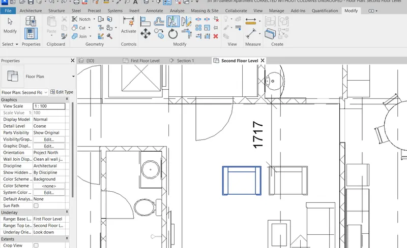
- Mirror the element by selecting required axis by MM shortcut
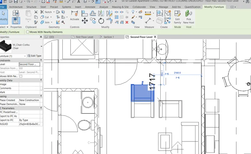
- Or enter DM shortcut key to Mirror the element by drawing axis
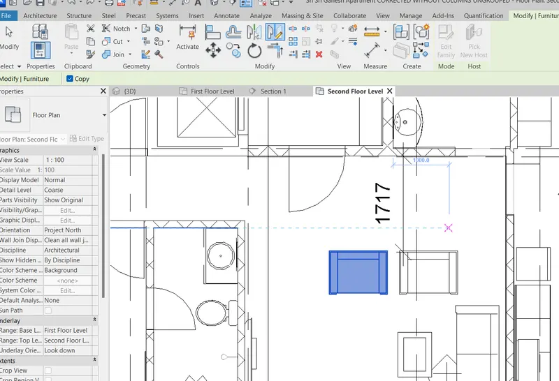
- Mirror the element by drawing the axis of mirror by DM shortcut
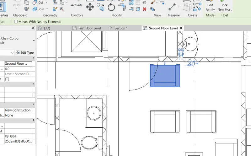
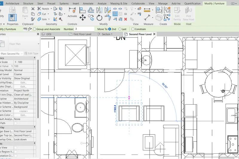
m. To create an array of model elements
- Select the element in the model to be Arrayed
- Then enter AR shortcut key to Array the element
- The Array tab will be selected and array icon will appear on cursor
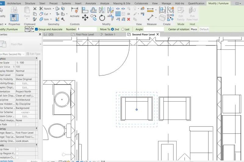
- Select the parameters for array like radial and number of array and path
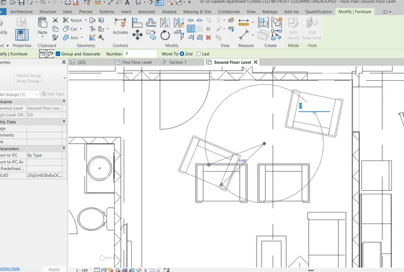
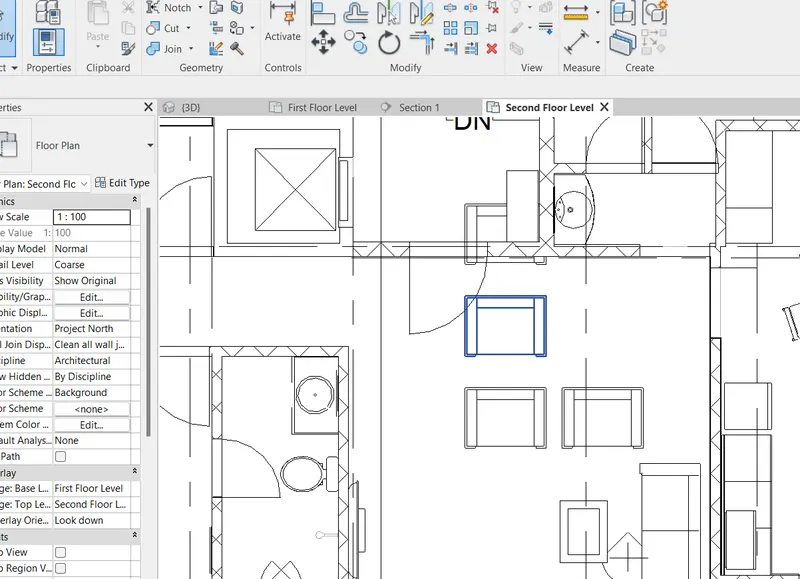
- Select the parameters for array like linear and number of array and path
2) Using Revit and the project used from week 6 to 8 prepare a schedule for the following
a. Walls
b. Doors
c. Windows
d. Material – Concrete/Wood
Ans 2.
INTRODUCTION: Preparing the schedule for elements from Revit model
AIM: To prepare the schedule of elements and materials from the project model created in previous challenge in Revit
PROCEDURE:
- Open the project Architectural model created in previous challenge
- Click on the View Tab
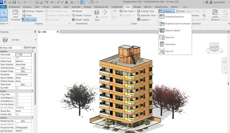
- Select the Schedules tab drop down menu
- Select the Schedule/ Quantities option
- Check the filter list and select Architecture check box
- From the list of categories select Walls
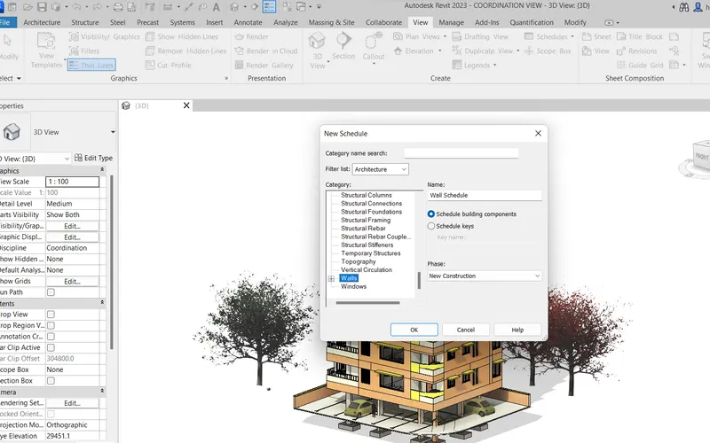
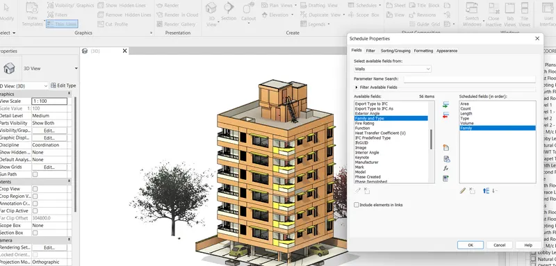
- Select the fields to be included in the schedule
- Click Ok and the schedule for all the wall will be created
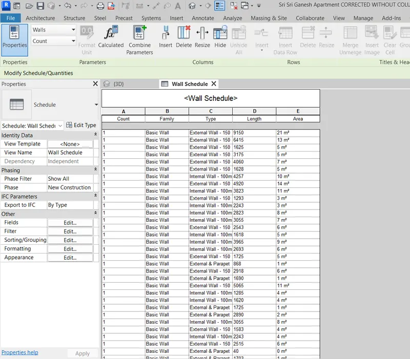
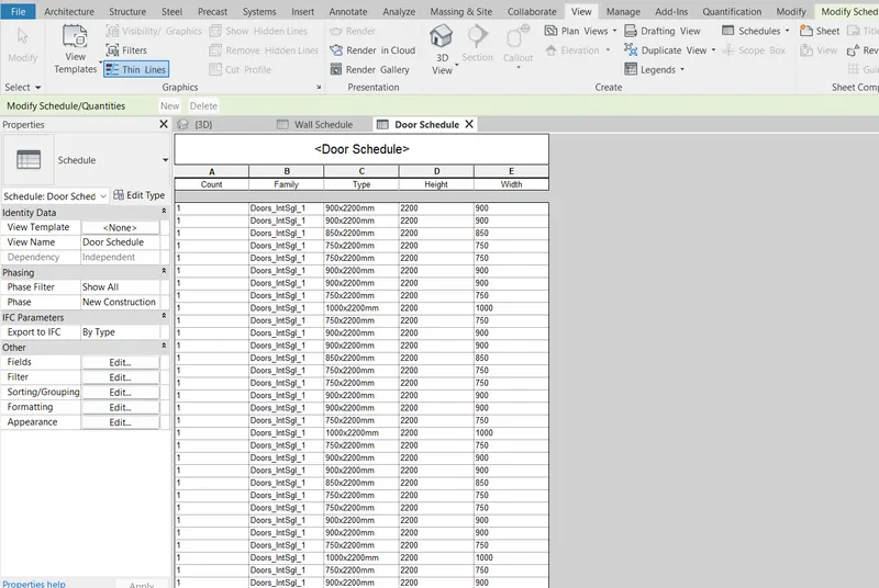
- Similarly in the View, Schedules and Schedules/ Quantities tabs select the Doors
- Select the fields to be included in the schedule
- Click Ok and the schedule for all the Doors will be created
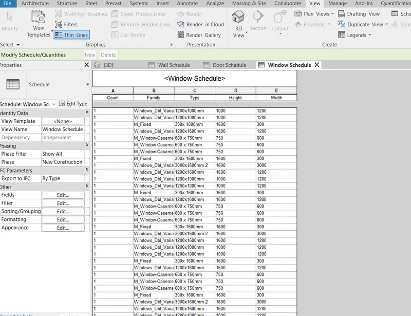
- Similarly in the View, Schedules and Schedules/ Quantities tabs select the Windows
- Select the fields to be included in the schedule
- Click Ok and the schedule for all the windows will be created
- For Material take off open the View tab, go to Schedules and click on Material Takeoff
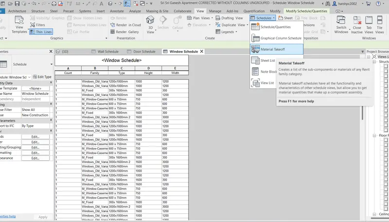
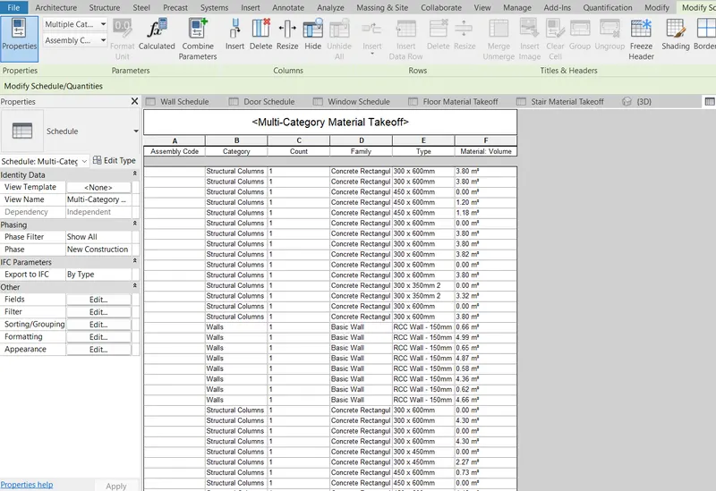
- Select the material category for material. I have selected Multi in the structural model
- Select the fields to be included in the schedule
- Click Ok and the schedule for all the structural elements are created
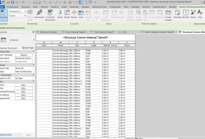
- Select the material category for Column in Structural model to take out quanties for concrete in columns.
- Select the fields to be included in the schedule
- Click Ok and the schedule for all the column concrete are created
CONCLUSION: Thus using Revit and the project created in the previous challenges we have created the schedules for Walls, Doors, Windows and material takeoff for the Concrete.
3) Using Revit Calculate area and volume of each room in the model with appropriate room tags applied to each room. Prepare a schedule report for area and volume of each room.
Ans 3.
INTRODUCTION: Calculating the area and volume schedule consisting of each room in the Architectural modeld by applying room tags in Revit
AIM: To calculate the area and volume of each room in the model by creating appropriate room tags and preparing the schedule report for the area and volume or each room the project model created in previous challenge in Revit
PROCEDURE:
- Open the project Architectural model created in previous challenge
- In the plan view create the room tags from the Architectural ribbon by selecting Room tag
- Include the area and volume from the Room & Area dropdown menu
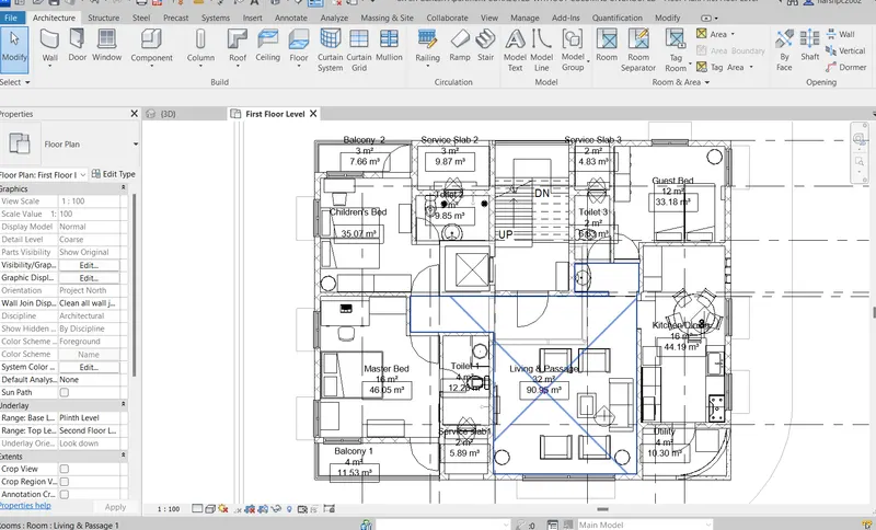
- Go to View tab and click on Schedules
- Create new schedule in Architectural filter list by selecting the Rooms category
- Select the required field for the schedule
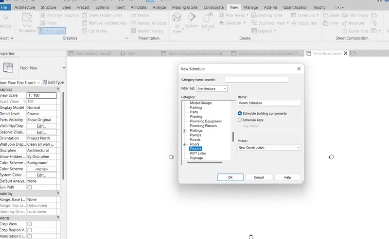
- The Room schedule is created with the room Area and Volume as shown in below screenshot
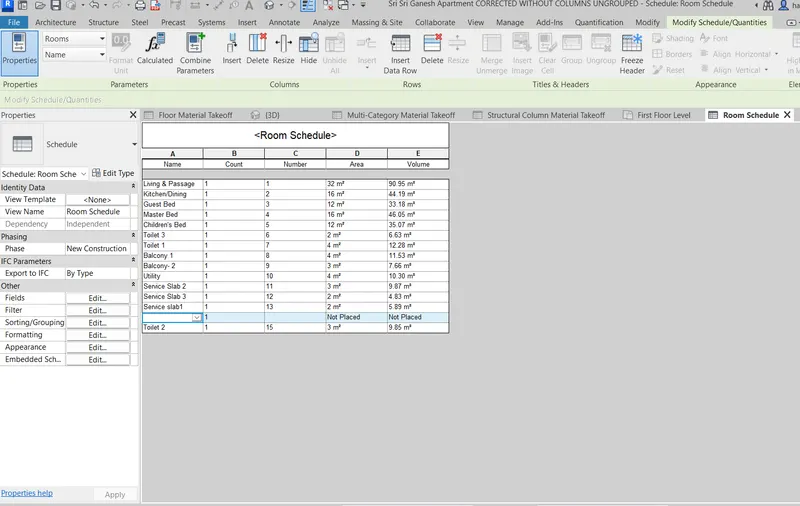
CONCLUSION: Thus using Revit we have provided the room tags with area and volume calculation and then created the Room Schedule showing area and volume of each room.
4) Using the same schedule using the unit cost rate for materials available in the internet, prepare total cost of materials used in the project
a. Total Cost of Materials
b. Individual Material Take off
Ans 4.
INTRODUCTION: Preparing the schedule with cost and individual material takeoff for elements
AIM: To prepare the schedule with total cost of material used in the project and the Individual material take off for the elements from teh previous schedules created.
PROCEDURE:
- Open the project Architectural model created in previous challenge
- In the plan view select the wall elements and in the Properties browser edit the element by entering the unit cost for the walls.
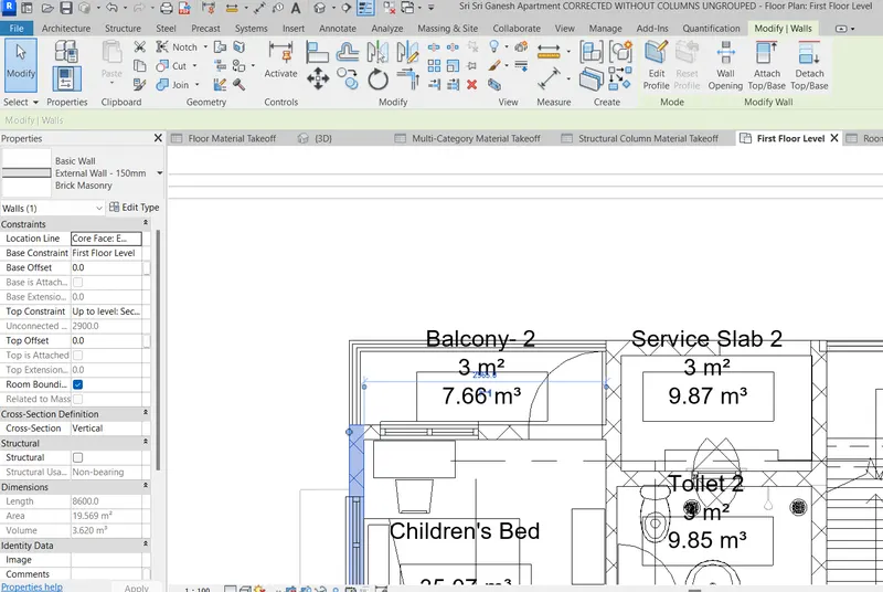
- In the Wall schedule prepared earlier add the field of Cost, the unit cost assigned will be seen in the schedule table in cost column
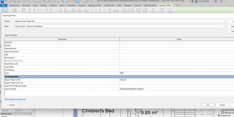
- Create one more column for Total cost
- Enter the formula for Total Cost as Cost x (Area/ unit area) in order to maintain the consistency of units
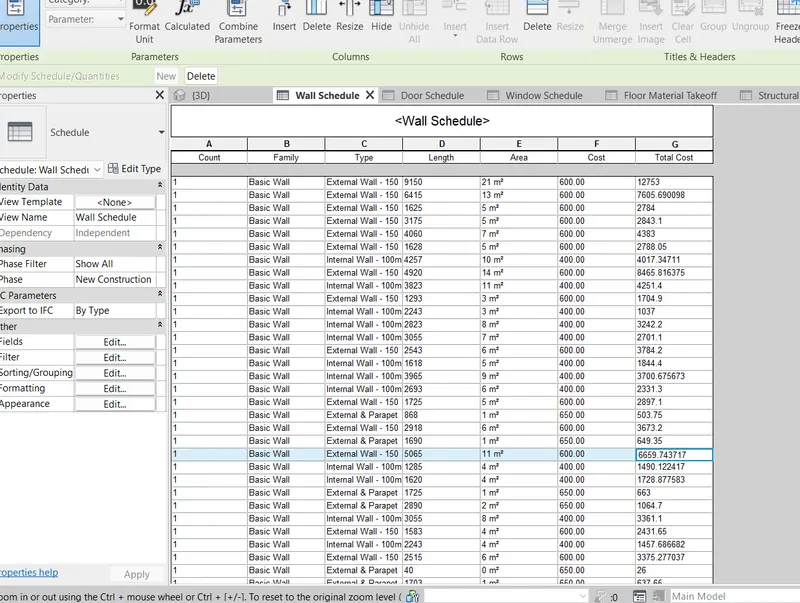
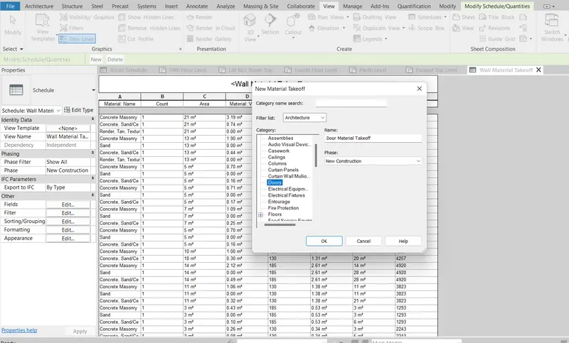
- To prepare material takeoff for all the materials of the walls
- In View- Schedules tab click on the Material Takeoff tab
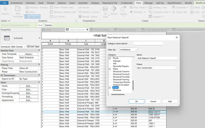
- Enter the fields required in the material takeoff and click Ok to create the Wall Materia Takeoff Schedule
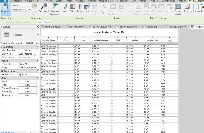
- If required the cost for the individual materials can also be assigned by Editing the Type of the element structure and entering the cost of individual material in the Structure of element
- The Material Takeoff for Wall along with the cost for one item assigned is shown below.
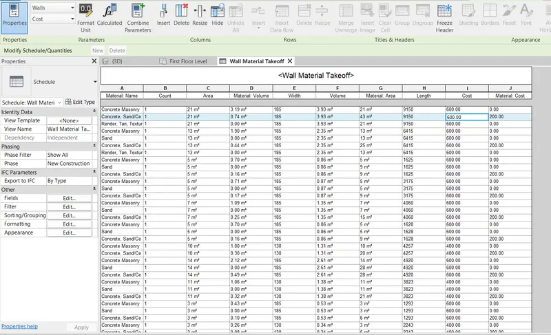
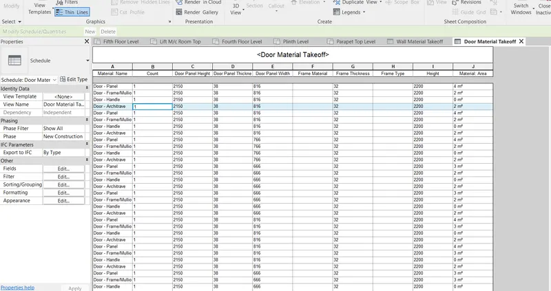
- Similarly the material takeoff schedule for the Doors can be prepared as shown below
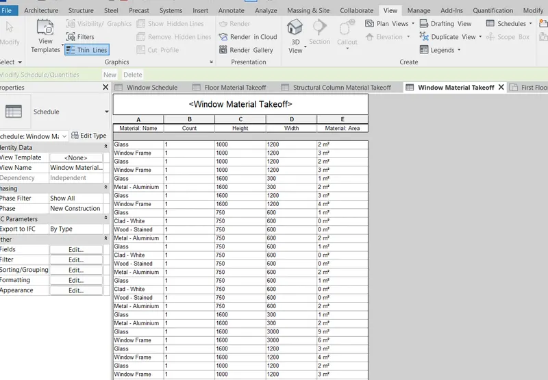
- Similarly the material takeoff schedule for the Windows can be prepared as shown below
5) Using the concept of Visual Programming discussed in class, list a flowchart for the following scenario
a. How to decide framings for a structure using Dynamo ?
b. If there is no water coming from the pipes
c. If request for money from client has been declined for the project
Ans 5.
INTRODUCTION: Listing flowchart for given scenario
AIM: To list the flowchart for the activities or scenario mentioned in the question
PROCEDURE: The flow charts for various scenario are mentioned below
a. To decide the framings for a structure using Dynamo following flowchart can be used
Excavation for footings -----> PCC for footings-----> Formwork for foundations-----> Reinforcement for footings and columns-----> Concreteing of footings-----> Removal of formwork-----> Curing of concrete-----> Formwork for columns-----> Concreting of columns-----> Removal of formwork for columns-----> Formwork for Beams-----> Reinforcement for beams-----> Concreting of Beams-----> Removal of formwork for beams------> Curing of concrete
b. For the scenario of no water coming from the pipes following flowchart can be used
Check the tap position ON-----> If water is coming OK or IF no water then check the main supply valve for ON position-----> If water is coming OK or IF no water then open the pipeline to check any obstruction ----> Remove the obstruction in pipeline and refix -----> Water is coming from the Pipes after removal of obstructio in pipeline OK Issue closed.
c. For the scenario of money from client declined for the project following flowchart can be used
Demand the money from the client for the project again------> If the money received OK or If money not received then give time line to Client for giving the money -----> If money received on the timeline then start the project or If money not received from Client on given timeline Stop the Project.
6) List the parameters associated with each model element
a. Wall
b. Floor
c. Door
d. Window
e. Table
f. Building
Ans 6.
Following are the list of parameters associated with mentioned each model elements
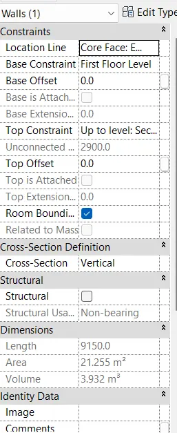
a. Wall:
1. Constraints- It consists of the line face of the wall, Floor level of the wall, Offset from the wall, Top constraint of the wall, Connected or unconnected, Boundary etc.
2. Cross section- Either Vertical, Slanted or Tapered
3. Structural- Either Structural load bearing or Non structural non load bearing
4. Dimensions
5. Identity Data
6. Phasing
7. IFC Parameters
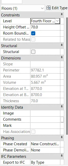
b. Floor:
1. Constraints - Level, Height Offset, Boundaries
2. Structural
3. Dimensions
4. Identity Data
5. Phasing
6. IFC parameters
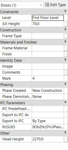
c. Door:
1. Constraints- Level, Sill Height
2. Construction- Frame type
3. Materials and finishes
4. Identity Data
5. Phasing
6. IFC parameters
7. Other - Head Height
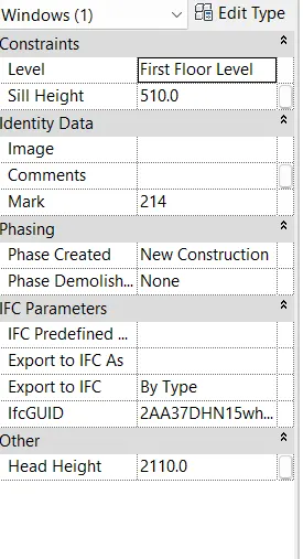
d. Window
1. Constraints - Level, Sill height
2. Identity Data
3. Phasing
4. IFC parameters
5. Others -Head height
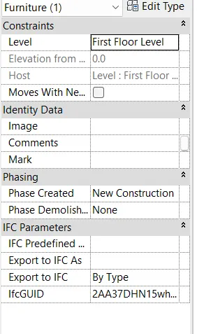
e. Table
1. Constraints- Level, Elevation, Host, Moves by nearby element
2. Identity Data
3. Phasing
4. IFC Parameters
f. Building
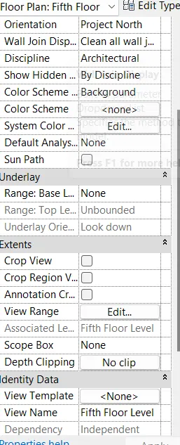
For Plan view
1. Orientation
2. Wall Join Display
3. Discipline
4. Show hidden lines
5. Colour scheme location
6. Colour Scheme
7. System colour schemes
8. Default analysis display style
9. Sun path
10. Underlay
11. Extents
12. Identity data
13. Phasing
For 3d view
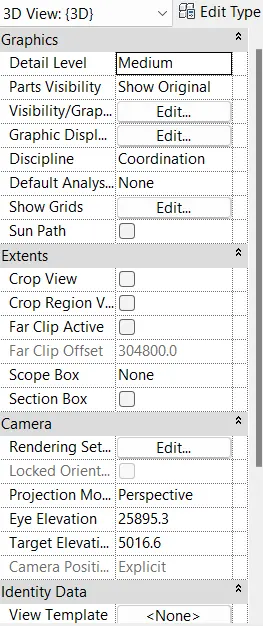
1. Graphics- Detail level, Parts visibility, Visibility/Graphics/ Graphic Discipline, Discipline, Default Analysis, Show grids, Sun Path
2. Extents- Crop view, Crop Region View, Far Clip active, Scope box, Section box
3. Camera
4. Identity data
5. Phasing