Preparing Schedule & Cost Estimation for a building using REVIT
ANS.1.
AIM :-
To use the shortcut keys as mentioned in the question
a. Using 3D model create a section box
b. To create similar doors and windows in a floor plan layout
c. To reduce the thickness of lines visible in plan views
d. To apply override settings to a floor in the model section view
e. To increase the range of visibility in a plan view
f. To select the previously selected items
g. To add annotations to the model views
h. To bring the model elements in line
i. To rotate the model elements
j. To move an object to another location
k. To copy a model element
l. To mirror an element about an axis
m. To create an array of model elements
INTRODUCTION:-
Revit software from Autodesk can be used to capture design intent efficiently and accurately in 3D; producing consistent, coordinated, and complete model-based building designs and documentation.
PROCEDURE :-
Open the model which you have created in earlier assignments
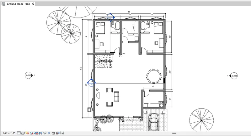
1.To create section box
Open model and then select the element which you want to create section box
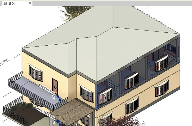
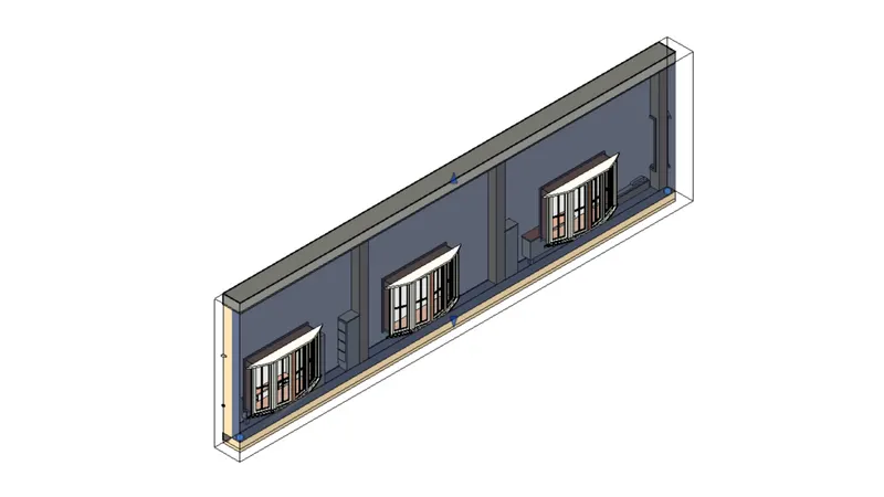
After selecting , type BX command and hence section box will appear.
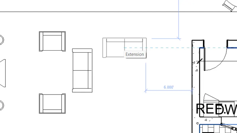
2.To create similar components in the floor plan layout
For this open the project and then select the component which you want to create similar copy
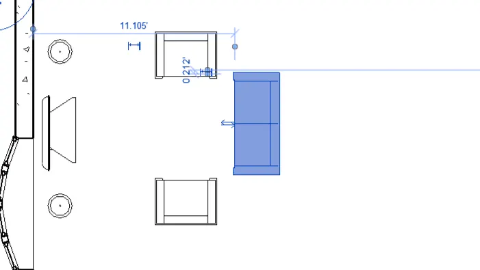
After selecting the model type the command and hence the model will be created similiarly
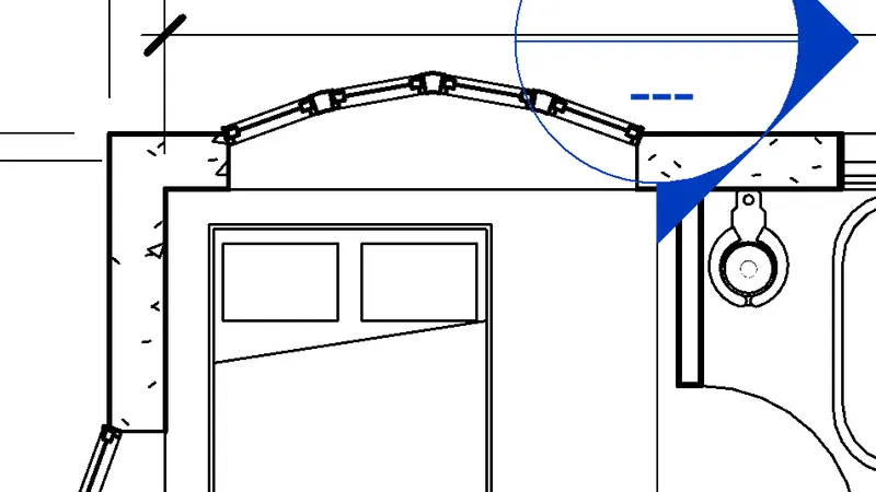
To reduce the thickness of lines
For this just go to the plan and see the lines they are thick in the starting
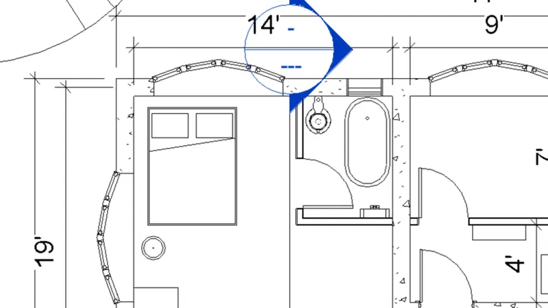
Then type the command TL that is thin lines command and now you can see the lines are become thin
To apply override settings to a floor in the model section view
For this go to the model floor plan view
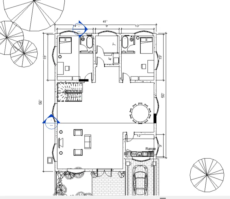
Then type VG command to see the visibility settings
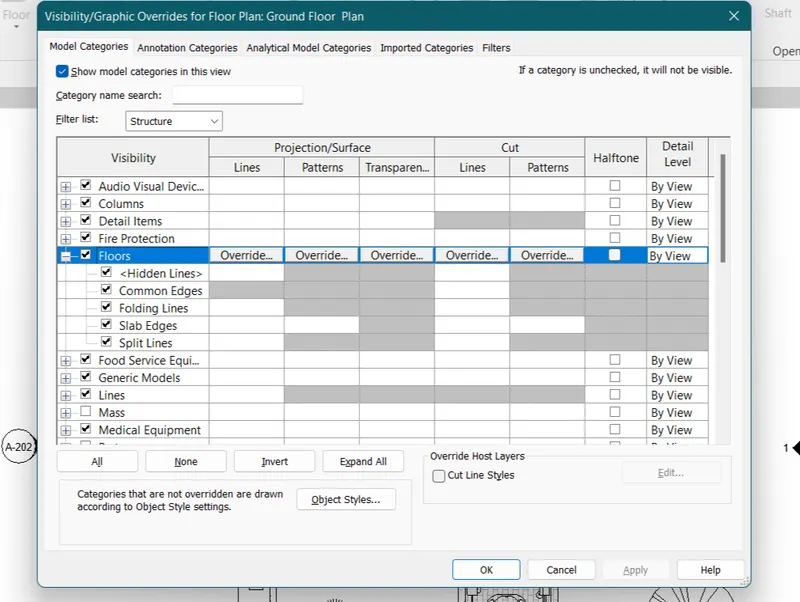
Then select the floor option from there and go to the override pattern option
A dailog box will open and change the pattern and colour as per your requirement
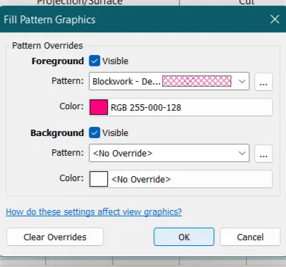
After that click ok
You can see the changes in the visibility panel
Click ok
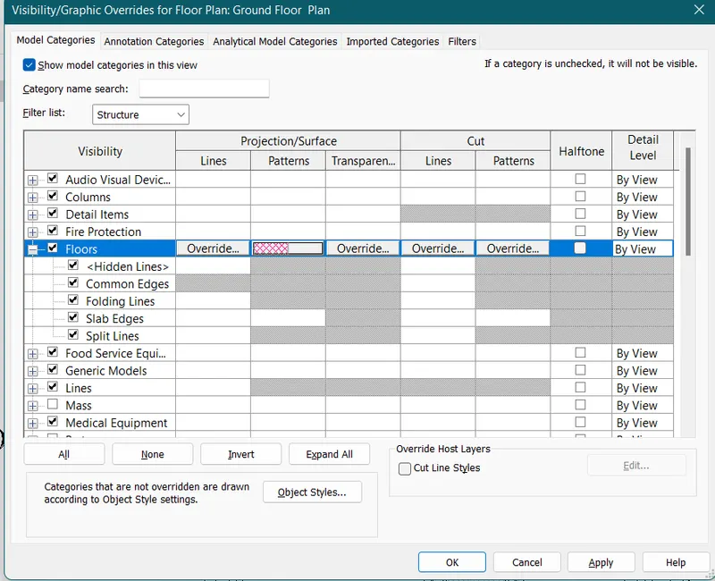
Hence the override settings have been applied
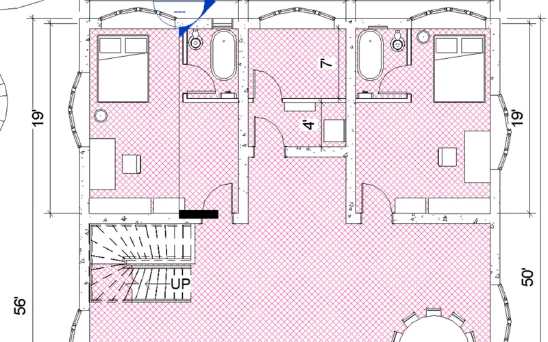
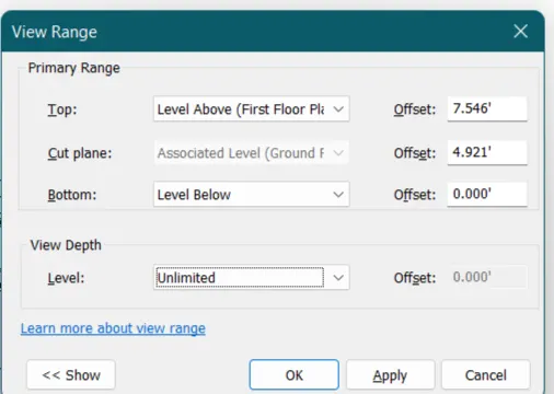
To increase the view range of the visibility in plan view
To increase the view range of visibility in the plan you type VR command and a dialogue box will open
Change the setting as per your requirement and click ok
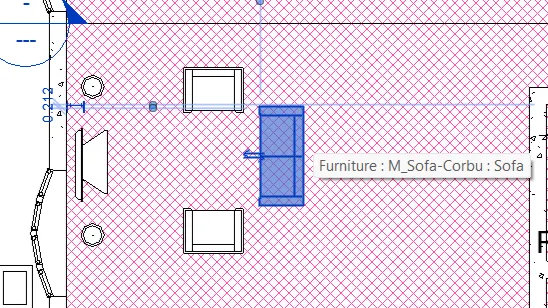
To select the previously selected items
Go to the model space and type the command and hence you can see the previously selected items
Add annotations to the model views
To add the annotations to the model views just type the Di command and the Ribbon bar will be changed in the annotation bar and there you can annotate the model

To bring the model elements in line
To align the model elements , Just use the AL command to align them
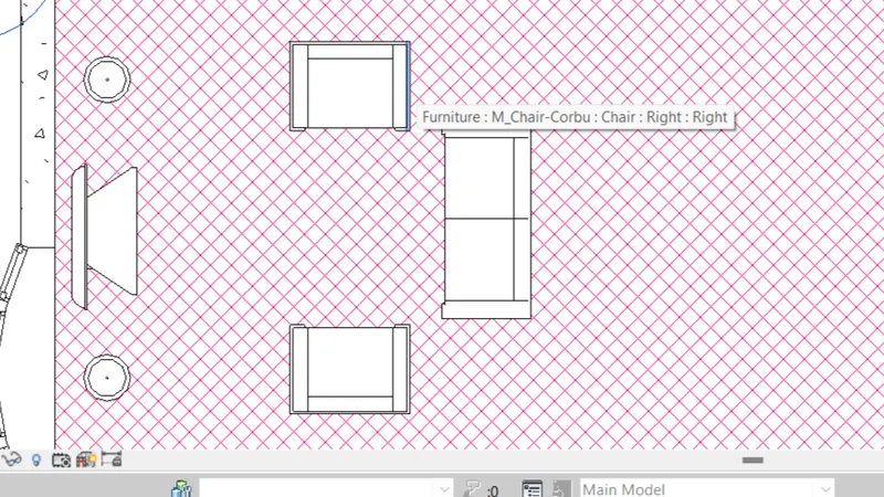
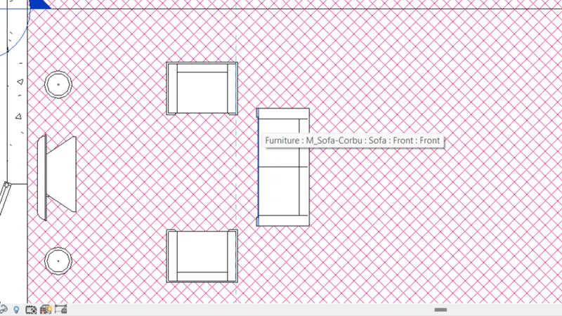
Hence the model has been aligned
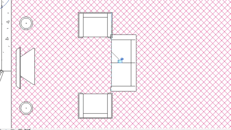
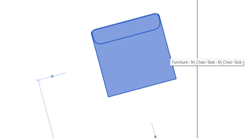
To rotate the model elements
To rotate the model element just select the model element which you want to rotate and after selecting type the command RO
After that provide the points as per the requirement where you want to rotate the model hai
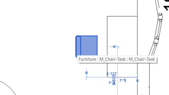
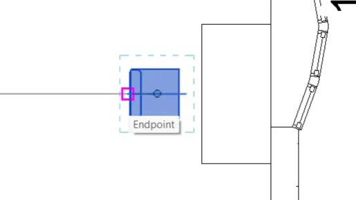
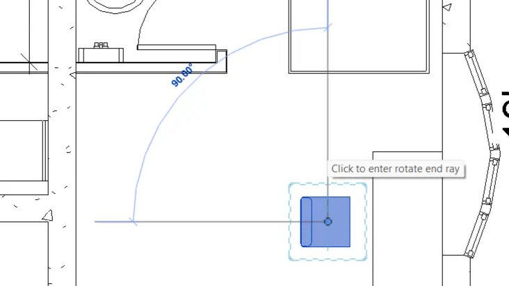
And hence the model has been rotated
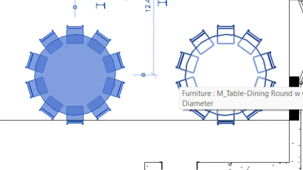
To copy a model element
To copy a model element just use the command CO
Select the element which you want to copy
Then specify points where you want to copy it and hence click ok
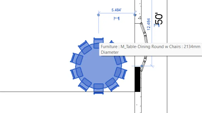
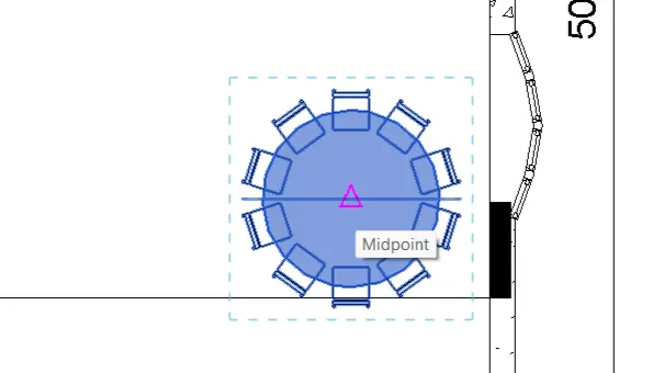
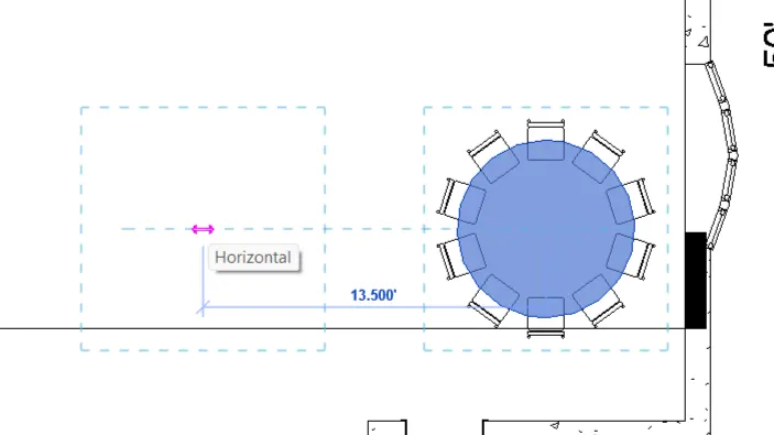 hence the model element has been copied
To move the model element to another location
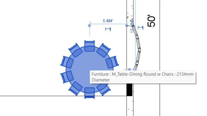
To move the model element to another location just use the command mo
First select the model element and then after selecting specify the point where you want to move the element and click there
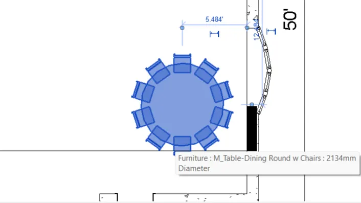
model element has been moved to another location
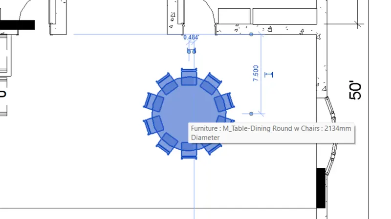
To mirror an element about an axis
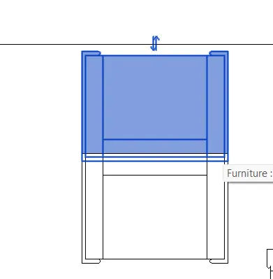
To Mirror an element about an Axis just use the command mm
Select the element which you want to mirror then type the command and then specify the mirror location and then done
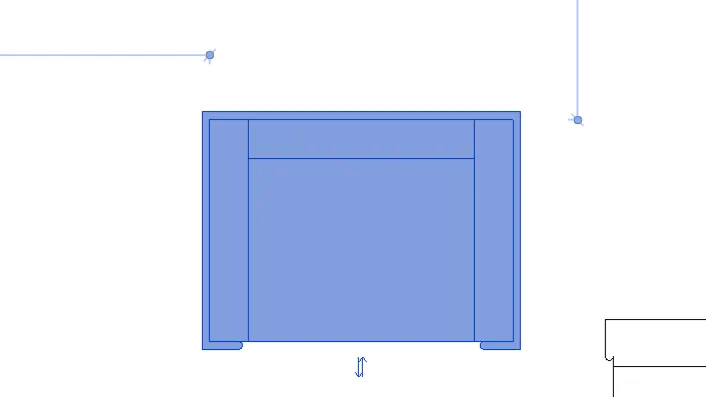
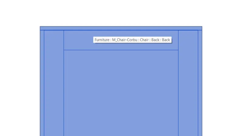
The object has been mirrored
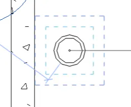
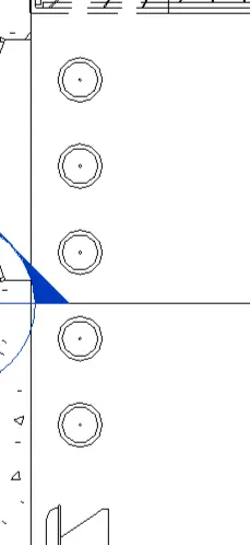
To create an Array of model element
Firstly select the model which you want to create array of it
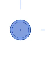
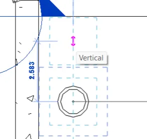
Then type the command AR and hence then specify the point where you want to array it
And also the number of components which you want
Hence the model has been arrayed.
RESULT :-
Hence different shortcut commands are being used to do the different tasks in revit software
ANS.2.
AIM :-
To create a schedule for walls doors Windows and materials using revit software
INTRODUCTION :-
Revit software from Autodesk can be used to capture design intent efficiently and accurately in 3D; producing consistent, coordinated, and complete model-based building designs and documentation.
PROCEDURE :-
Open the model in which you want to create the schedule
Then go to the view tab and click on the schedule option
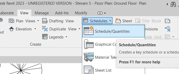
After that a new dialogue box will open select the wall category for the scheduling of walls
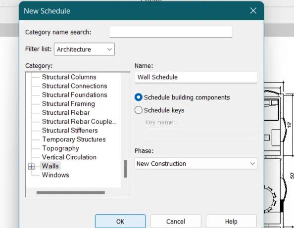
After that select the field in which you want to schedule the wall
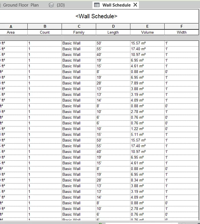
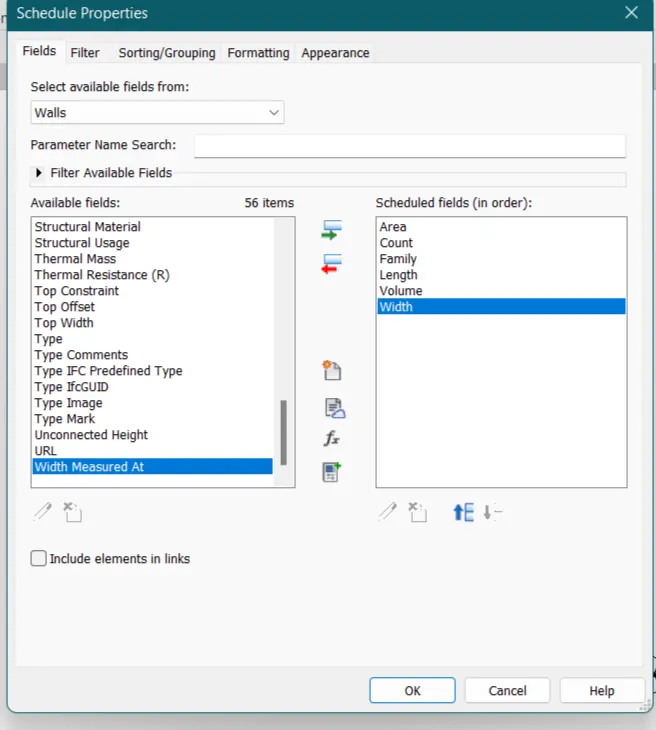 hence the scheduling of wall has been done
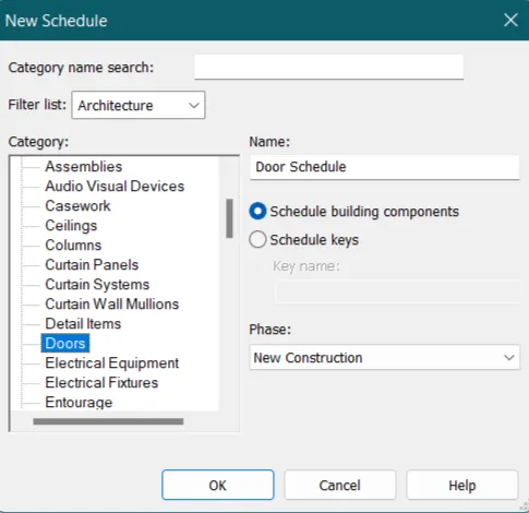
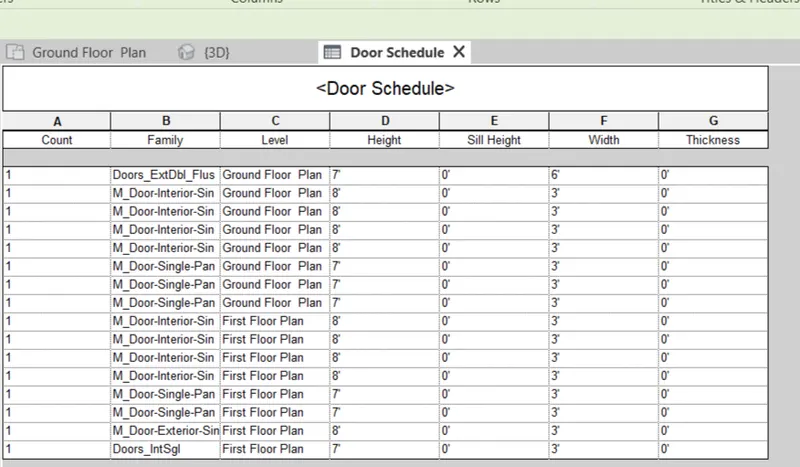
Similarly to schedule for door
Select the door option from the dialogue box
Then click ok
Then select the parameters which you want to see in the scheduling
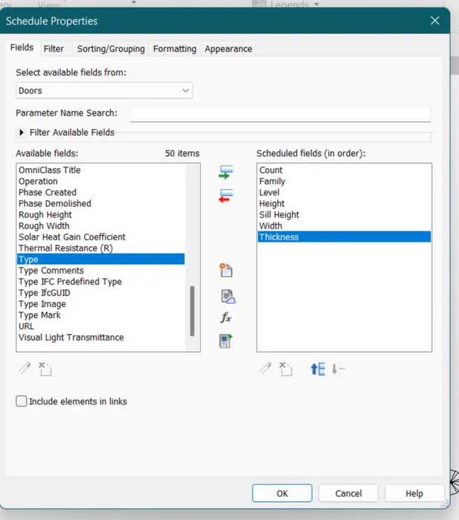
And hence our door schedule has been created
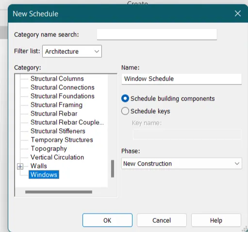
for the scheduling of Windows
Select the window option present in the dialogue box
Then select the parameters which you want to see in your window schedule
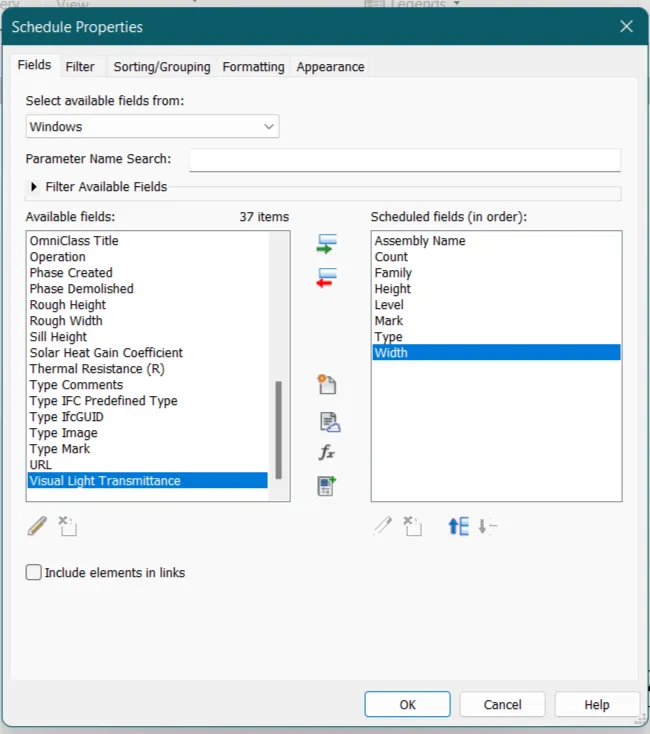
And hence the window schedule has been created
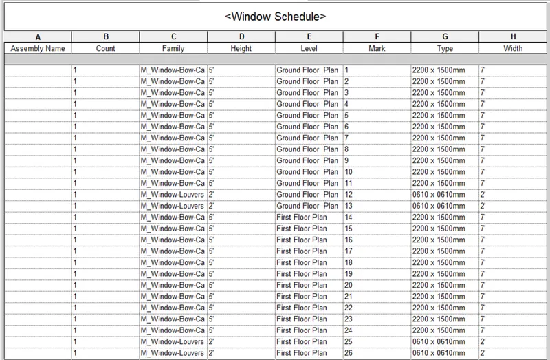
Now to schedule for materials
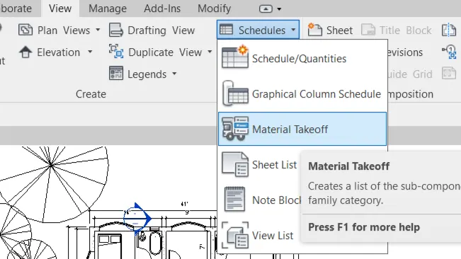
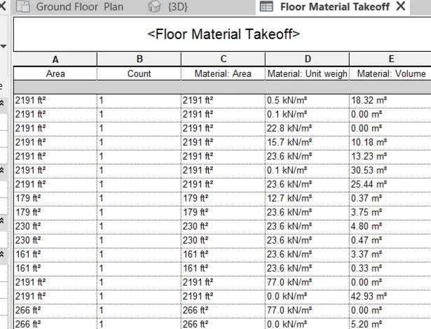
Go to the view tab and then select the material take off option from schedule
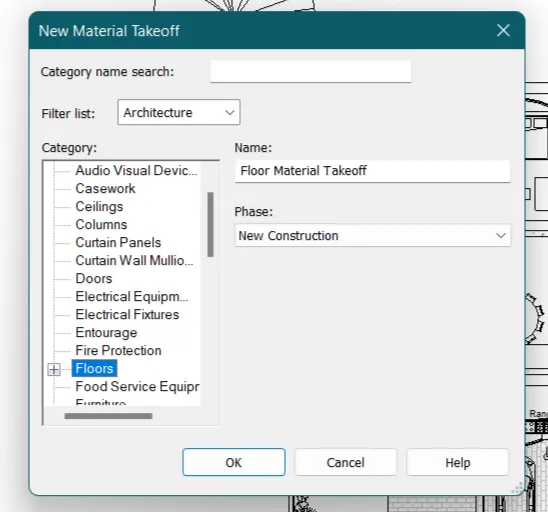
New dialogue box will open select the floor option from there
After that assign the parameters which you want to see in your schedule in
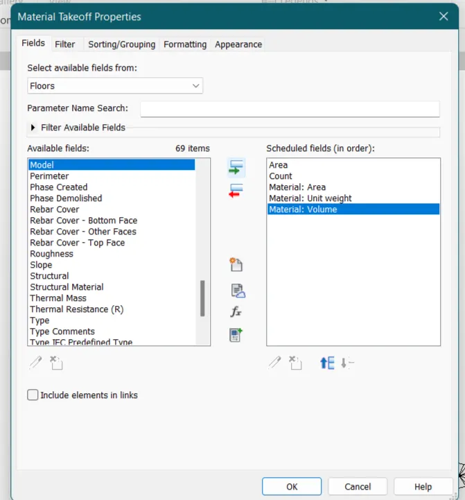
And hence the material scheduling has been created for floor
ANS.3.
AIM :-
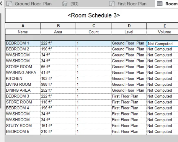
To Calculate area and volume of each room in the model with appropriate room tags applied to each room. Prepare a schedule report for area and volume of each room.
INTRODUCTION :-
Revit software from Autodesk can be used to capture design intent efficiently and accurately in 3D; producing consistent, coordinated, and complete model-based building designs and documentation.
PROCEDURE :
Open the mod project in revit software
Then go to view tab and click on schedule option and select schedule /quantities
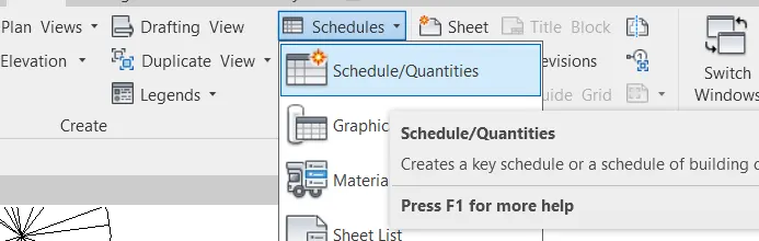
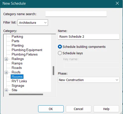
After that a new dailog box will open
Just select the room option from there
Then assign the parameters which you want to see in your schedule
Select Area and Volume parameters as mandatory as mentioned in question
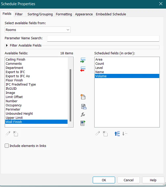
Hence the scheduling has been done for room with area and volume
RESULT :-
Hence the scheduling has been done of rooms with area and volume parameters.
ANS.4.
AIM :-
To do the scheduling using the unit cost rate for materials available in the internet, prepare total cost of materials used in the project
a. Total Cost of Materials
b. Individual Material Take
INTRODUCTION :-
Revit software from Autodesk can be used to capture design intent efficiently and accurately in 3D; producing consistent, coordinated, and complete model-based building designs and documentation.
PROCEDURE :
Open the revit model
Then go to view tab and click on schedule option then select the material take off option
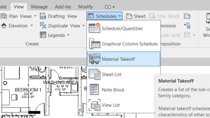
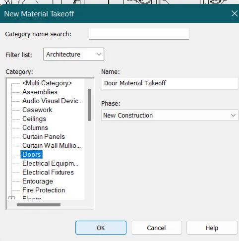
A new dailog box will open
Select door parameter and then click ok
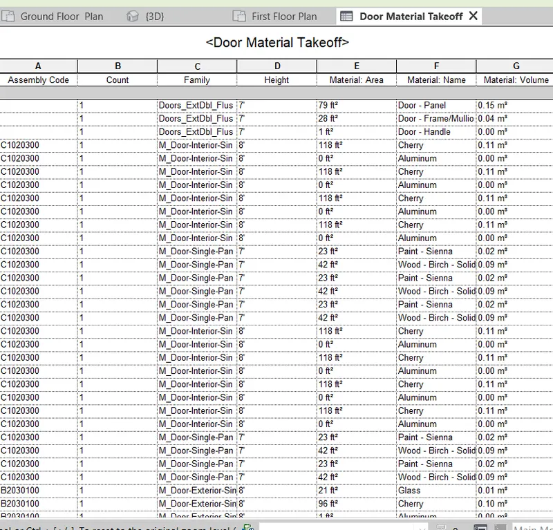
Assign the parameters for the door which should be visible in the schedule
Click ok to proceed
Hence,Door material takeoff schedule has been created.
Now for cost
Go to the floor plan
select the wall
then go to Edit type in project browser
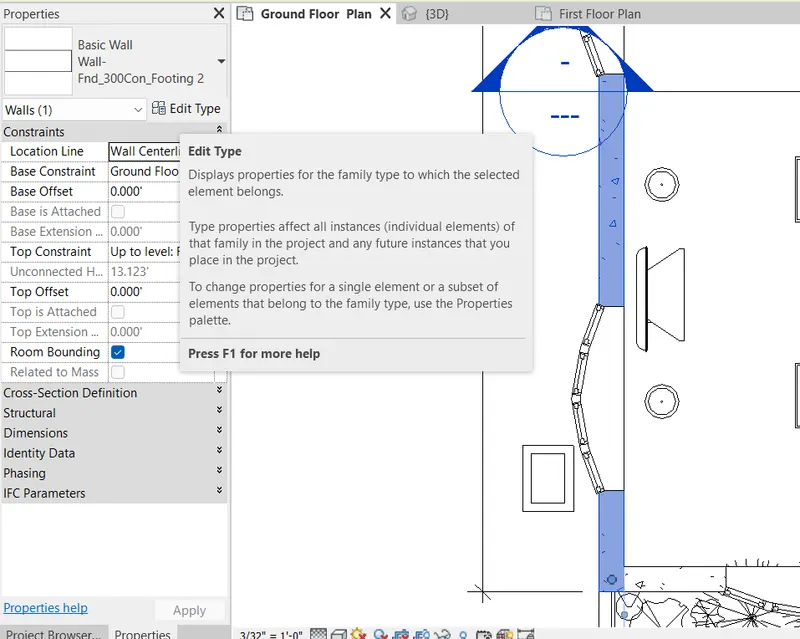
A dailog box open
Search for Cost option
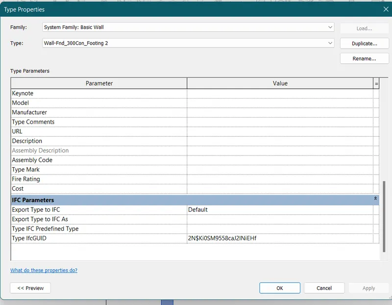
Enter the cost you want to assign for your wall
Here i entered Rs8800 for the wall construction
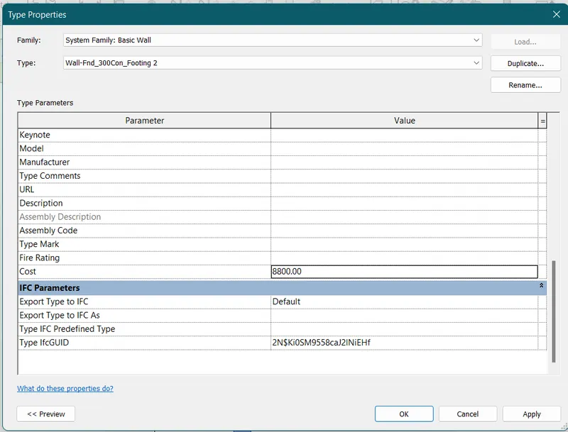
Then go to schedule option
and select material take off
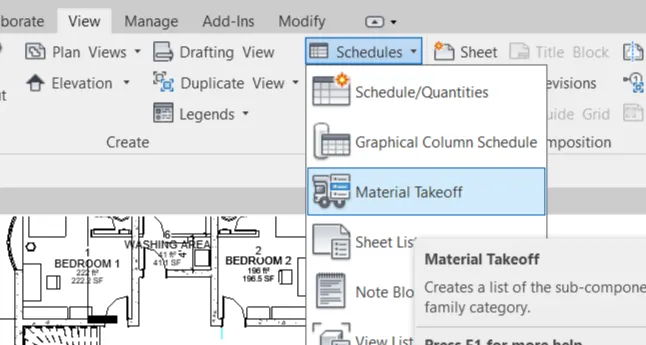
Then select the wall option
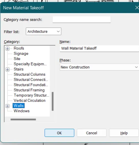
Assign the parameters which you want to see with a dummy parametere included
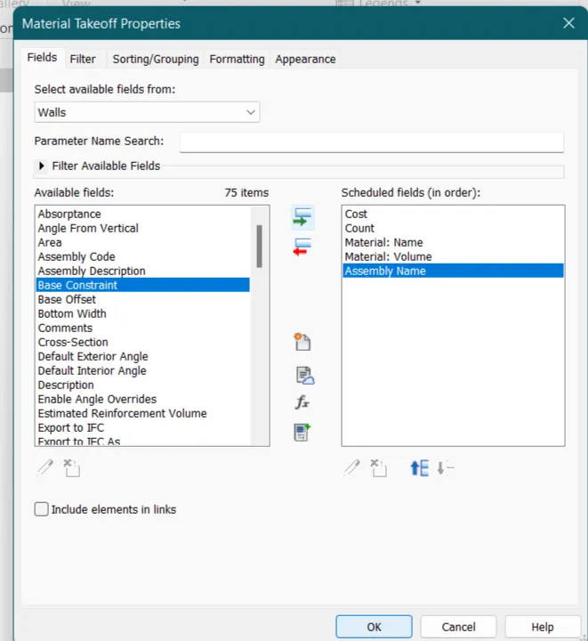
Hence ,scheduling is created but total cost is not present
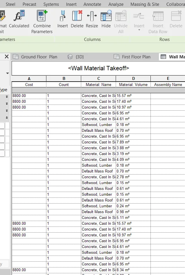
Select the dummy column and Go to Fx Calculated option
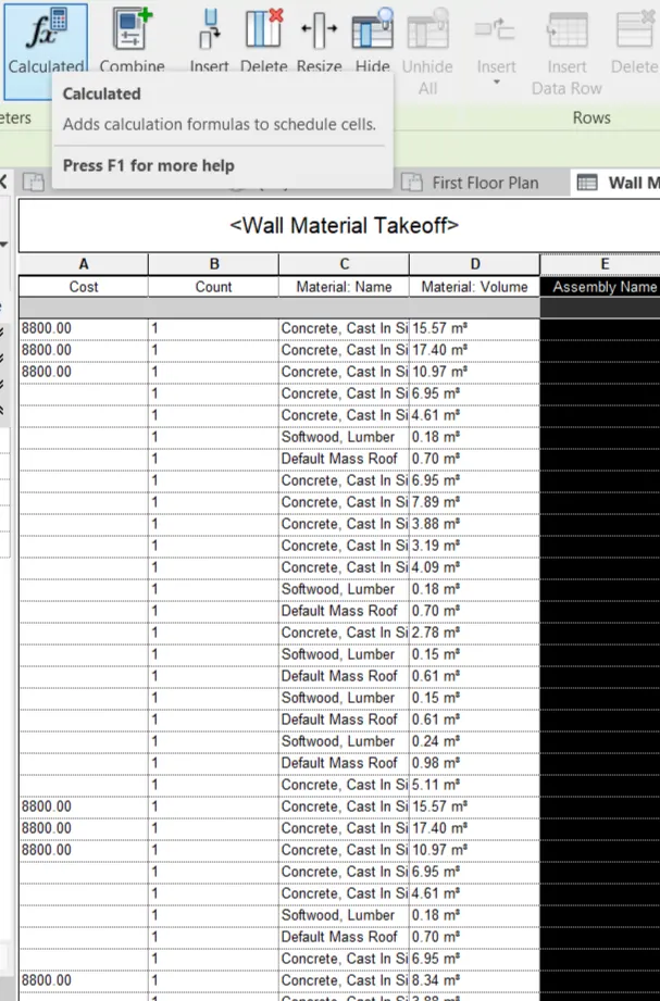
Enter the name and the formula for the total cost calculation
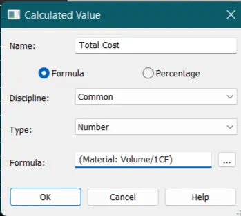
Now the total cost is calculated.
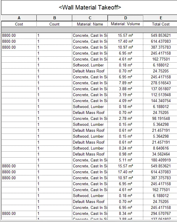
RESULT :-
Scheduling has been done for the material and with total cost also with appropriate rates.
ANS.5.
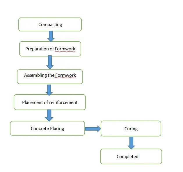
a.How to decide framing for a structure ?
Ans.
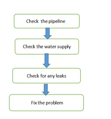
b.If there is no water coming from the pipes
Ans.
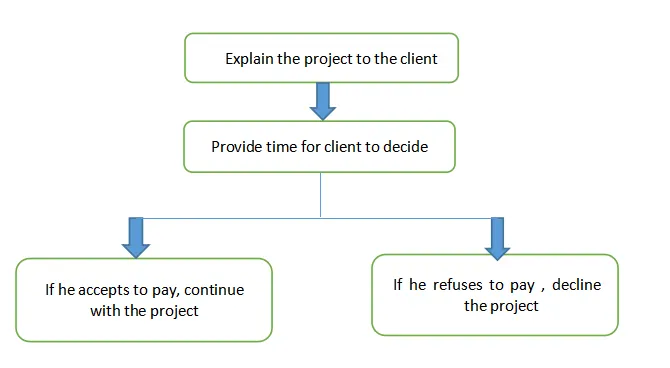
c.If request for money from client has been declined for the project
Ans.
ANS.6.
AIM :-
To List the parameters associated with each model element
a. Wall
b. Floor
c. Door
d. Window
e. Table
f. Building
INTRODUCTION :-
Revit software from Autodesk can be used to capture design intent efficiently and accurately in 3D; producing consistent, coordinated, and complete model-based building designs and documentation.
PROCEDURE :
Open the revit software and the project model
For walls
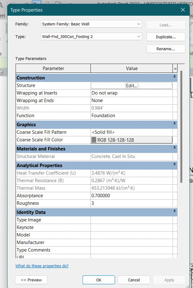
Select the wall and then go to the edit type option
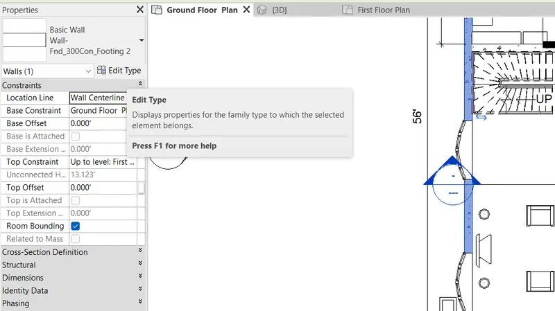
New dialog box will open and hence the parameter such as construction structure etc are the parameter for walls
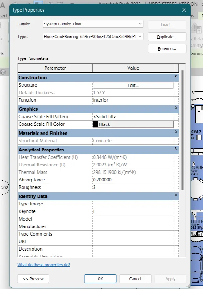
For floor
Select the floor from the project model
Go to edit type in project browser
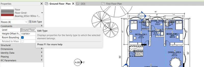
Hence the parameters are now shown for floor
For Door
Select the door from your model project
Go to edit type option in project Browser
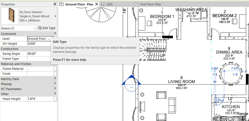
Hence the parameter for door are shown
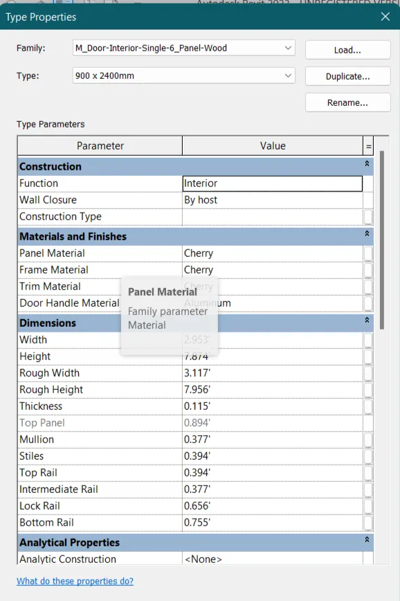
For Windows
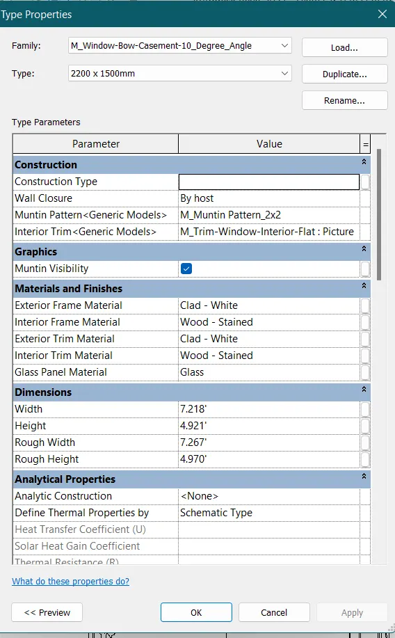
Select the window and then go to the edit type option from Project Browser
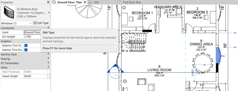
A type property dialogue box will open in with the parameters are visible for Windows
Parameter for table
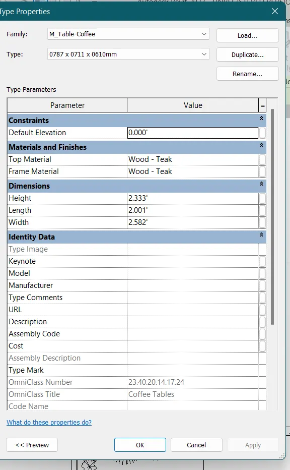
Select the table and then go to the edit type option in the project Browser
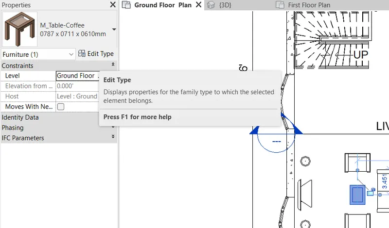
And hence a type properties dialogue box will open there you will find the parameter for table
For building components just select the components for which you want to see the parameter and then go to the edit type option and then the parameters are visible in the type properties dialogue box.
RESULT :-
Hence the parameters associated with different model elements are being showed with the help of revit software