Power electronic converter and duty cycle
AIM :
- Why power electronics circuits are efficient? In practice, which types of losses occur in power electronics circuits?
- A. Develop a Simulink model for generating pulses for a simple power converter circuit? (Hint: Blocks : sine wave,carrier wave,relationaloperator,scope) B. Simulate a simple power converter circuit (Default) with the above results.
- Explain the difference between VFD and Vector control drive. Can we use VFD method for induction motor in EV application?
STUDY-1>
POWER ELECTRONICS:
Power electronics is one of the technology that involves the use of solid state electronics to the control and conversion of electric power. The electronic systems are concerned with transmission and processing of signals and data. As we already know that in power electronics substantial amounts of electric energy are processed. The first ever power electronic devices are mercurt arc valves, but with improvement in technologies the coversion is mostly done using semiconductor devices such as thyristors, power transistors, IGBTs, diodes and MOSFETs. Power electronic devices maybe used as switches or amplifiers. if we take an example of an ideal switch, An ideal switch is either open or closed and dissipates no power; it also withstands an applied voltage and no current is passed with sero voltage drop. Sermiconductor switvhes can be used in this ideal property which makes power electronic switching and operations very efficient . If the take the case of amplifier, the current through the device varies continously according to a controlled input.
LOSSES IN POWER ELECTRONIC DEVICES
Generally there are three main losses:
- Conduction losses
- Switching losses
Conduction losses:
When the device runs in this full operating condition, the current in the device is whatever required by the circuit and the voltage at the terminals is the voltage drop due to the device itself. These types of losses are directly linked to the duty cycle. Conduction losses are simply the product of the current flowing through a switch or diode when its forward biasedand the voltage drop across it. When the transistor is off, it carries a leakage current. However, since the leakage current is small, it doesn't varies with voltage, and thus the transistor power loss is zero. The small voltage drop acroos the transistor when it is ON is called the saturation voltage.
Switching losses:
Switching looses occurs when the device is transtioning from the blocking state to the conduction state and vice-versa. The interval is characterised by a significant voltage across terminals and significant current flowing through it. The energy dissipated is each transition is multiplied to the frequency to get the switching losses. These switching times not only introduce power losses in the device but also limit the switching frequency of the device. In addition to a conduction loss, a real switch has switching losses because it cannot change from the ON state to the OFF state simultaneously. A switch takes time to turn On and a finite time to turn off.
STUDY-2>
Here, we have to develop a simulink model for generating pulses for a simple power converter circuit with the help of(sine wave, carrier wave, relational operatorand scope). and after getting the required pulse we have to implement it in a simple power converter circuit to check the desired result.
- SIMULINK MODEL FOR GENERATING INPUT PULSES:
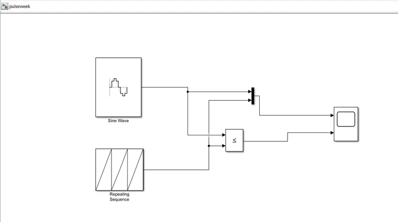
Here we used a combination of two different wave generators for input signals. That are sine wave and repeating sequence generator.
Relational operator compares both signals and sends a resultant signal which depends on what condition we give and the output signal of the relational operator is used to operate the switching action of an ideal switch.
The scope here is used to plot the generated input signal waveform.
Sine wave input block characteristics:
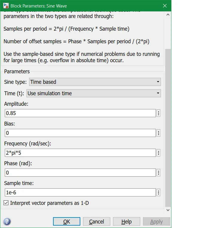 --> Here we put input values for generating a desired sine wave for simulation.
Repeating sequence input block characteristics:
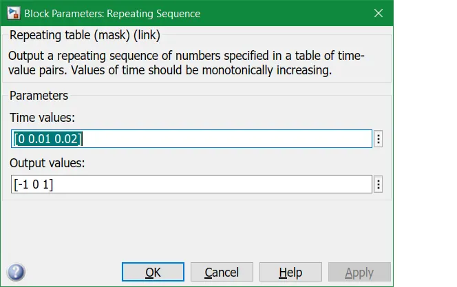 --> Here i have entered the required time values and output values.
OUTPUT FOR PULSE GENERATING INPUT PULSES:
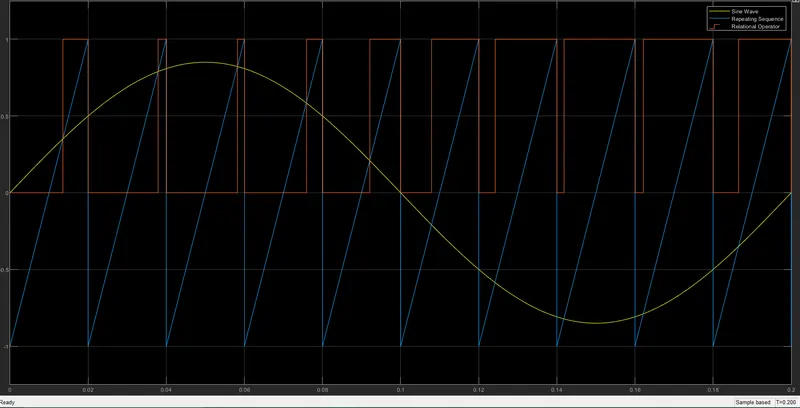
- The above plot shows 3 different wave forms. In which first is the sine wave and second is the repeating sequence. The third wave form is the comparision of the first and the second waves. Here the relational operator block works as the comparator. When the sine wave signal is greater than the repeating wave then the relational operator produces a high input signal and the oart where the sine wave is less than the repeating sequence then the relational operator produces a low signal.
Now we have generated the input pulses.
SIMULINK MODEL FOR SIMPLE BOOST CONVERTER CIRCUIT :
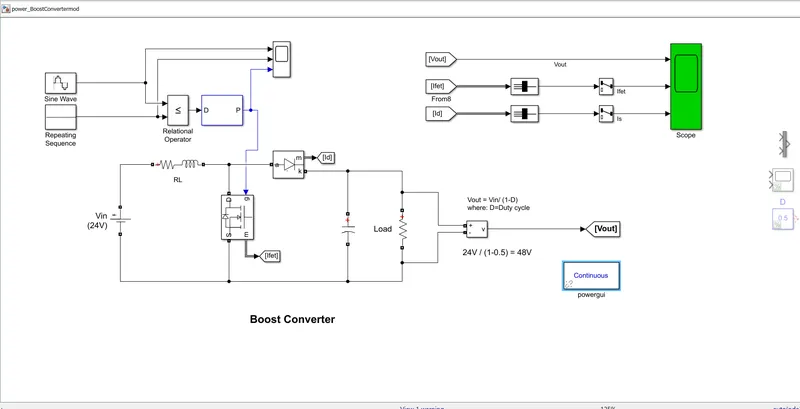
Here we have used a simple predefined matlab model for boost converter and we gave the generated pulses as an input to gate of the MOSFET. In this matlab model an ideal switch is used to regulate the input 24volts into 48volts. Here, the boost converter steps up voltage from its input source to its output voltage. In continous conduction mode(current through the inductor never fails to zero). The theoretical function of the booost converter is Vout/Vin= 1/(1-D). where D is the dutycycle.
In this example, the converter is feeding an RC load from a 24V source and PWM frequency is set to 20KHz.
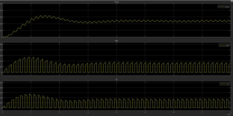
After simulatimg the above model we are able to observe the waveforms on scope. In the output graph we observed that the mean or average value of the load voltage (Vout) is very close to the theoretical value of Vout. That is Vout= 24/(1-0.5)=48V . This model represents a converter that steps up Dc voltage as driven by an attached controller and gate-signal converter. These are also known as step-up voltage regulators because they increase voltage magnitude. In this model one switching device MOSFET (N-channel metal oxide semiconductor field effect transistor) .
Components used in this circuit are:
- DC voltage source
- Voltage measurement block
- Series RLC circuit
- Power diode
- Mosfet
- Pid controller
- Scope
- Bus to vector block
- Selector block
Output:
The output variation in the scope is shown. It shows three waveforms In which first is the output voltage of which the mean value is very close to the boosted voltage 48V. Second is the ideal switch block and third is the diode block.
The plot shows the switching action of ideal switch and diode with a change in input signal
. 
STUDY-3_>
Variable frequency drive
A VFD is a type a motor controller that drives an electric motor by varying the frequency and voltage supplied to the electric motor. Frequency is directly related to the motor's speed. In other words, The faster the frequency the faster is the rotations per minute. When the motor isin,t needed to run at full speed the VFD can be used to ramp down the frequency and voltage to meet the requirements of electric motor load. As the applications motor speed requirements change the VFD can turn up or down the motor speed to meet the speed requirement.
A variable frequency drive is a device used in a drive system which consists three main subsystems :Acmotor, main drive/ operator interface.
AC motor: The ac electric motor used in a VFD system is usually a three phase induction motor. some types of single-phase motors or synchro motors can be advantageous in some situations.
ControllerThe VFd controller is a solid state power electronics system consisting of three distinct sub-systems:a rectifier bridge converter, a direct currentDC link, and an inverter.
Working principle : It's the electronic controller specifically designed to change the frequency of the voltage supplied to the induction motor.
- Advantages: Easy and straight method to control
- It maintains a constant torque
- Disadvantages:Due to stator drop compensation efficieny is reduced
- Range is less than field oriented control.
Vector control drive
Vector control drive is also called field oriented control(FOC), in which the stator current of three phase AC induction motor are identified as two orthogonal components that can be visualized as two vectors.One component defines the magnetic flus of the motor, the other defines the torque. The control system of the drive calculates the corresponding current component refrences from the flus and torque refrences is given by the drive,s speed control. If the frequency is increased above 50 Hz the motor will ru faster than its rated speed, and if the frequency of the supply voltage is less than 50Hz, the motor will run slower than its rated speed.
A proportional integral controller (PI) is used to keep the measured current components at their refernce values. the pulse width modulation of the variable frequency drive defines the transistor switching according to the stator voltage references that are putput of the PI current controllers. Vector control generates a three-phase PWM motor voltage output derived from a complex voltage vector to control a complex current vector derived from the motor's three phase stator current input through projections or rotation back and forth betwwen the three phase speed and time-dependent system.
Advantages:
- Improved torque response.
- Increased and efficient speed accuracy
- reduction in size of motor ,cost and power consumption.
- fout quadrant operation
- Efficient troque control at low speeds and frequencies.
Disadvantages:
VFD complex control mechanism.
EV implementaion
When it is wanted to run the motor down to zero speed it is not possible for VFD, and practically below 10 Hz, the 50 Hz motor cannot start with full Lod when using VFD method.As we know that VFD is low efficient and it has higher amount of losses in form of stator compensation and thus it is not widely used in the EV industry. On the other hand vector control method offers much better control at higher efficiency because there are two vector control methods, Direct or feedback vector control(DFOC) and Indirect or feed forward vector control(IFOC), Nowadaya IFOC are more commonly used in EV industry because in a closed loop mode such drives more easily operate throughout the speed range from sero speed to high speed field weakening.