Planetary Gear
Aim: To carry out motion analysis of Planetary Gear train consisting of a ring gear, sun gear, four planet gears and a carrier of the planet gears.
Introduction: A planetary gear train also called an epicyclic gear train typically consists of a ring gear which is an internal spur gear, a sun gear which is at the center of the system and is a spur gear, and one or multiple planet gears which are also spur gears. They are called planetary gear system because they resemble our planetary system, the planet gears orbit around the sun gear and are encased in the ring gear. If there are more than one planet gears, the system also requires a carrier. Any one of the gears is fixed, one is given input and the third gear is the output, so there are number of different applications according to the torque requirements. One of the most widely used application is in the automatic transmission of an automobile vehicles.
Procedure: First, we need to know the pitch circle diameter and the number of teeth of each gear in order to make a 3d model of it. We are given the module of every gear as 2.5 and as we know that module of a gear is the ratio of its pitch circle diameter and the number of teeth. So, we calculate the unknow values as shown below.
For Ring gear,
Given, Module(m)=2.5, Number of teeth=46, So, PCD(ring gear)=2.5*46=115mm
For Sun gear,
Given, Module(m)=2.5, Number of teeth=14, So, PCD(sun gear)=2.5*14=35mm
For Planet gears,
Given, Module(m)=2.5,Number of planet gears=4, PCD(planet gear)=(115-35)/2=40mm, Number of teeth=40/2.5=16
Shaft Diameter for the sun gear is assumed to be 20mm for the sun gear and 15mm for the planet gears. Face width of all the gears is taken as 25mm.
Using these dimensions, the planetary gear train including the carrier for the planet gears is modelled, assembled and proper constraints are given in order to restrict their DOF and to ensure that analysis performed is as close to real life as possible. Then the motion analysis is performed by giving the input velocity of 200 RPM.
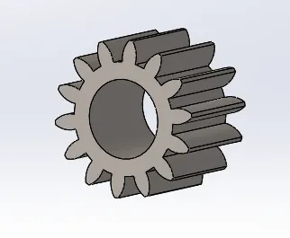
1. Sun gear
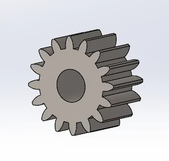
2. Planet Gear
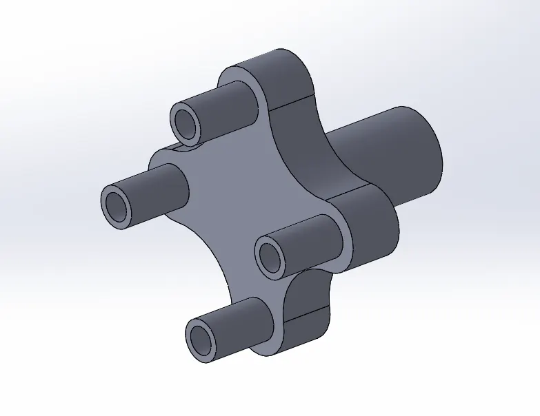
3. Carrier
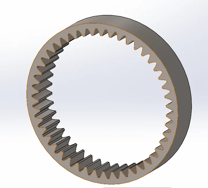
4. Ring gear
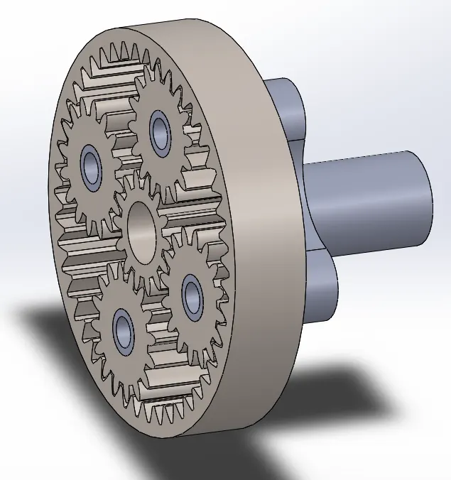
5. Planetary Gear system assembly
Observations:
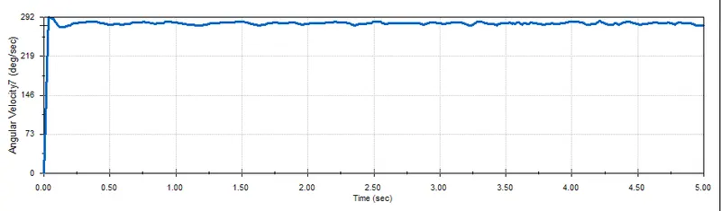
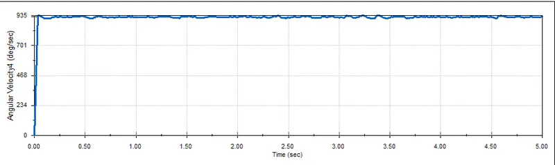
The motion analysis is done by considering 3 cases and carried out for 5 seconds. The angular velocity plot is obtained and observed.
In every case, the input, the output and the fixed gear are changed.
case 1
| Sl.No | Input | Output | Fixed |
| 1 | Sun Gear | Carrier | Ring Gear |
case 2
| Sl.No | Input | Output | Fixed |
| 2 | Ring Gear | Carrier | Sun Gear |
case 3
| Sl.No | Input | Output | Fixed |
| 3 | Sun Gear | Ring Gear | Carrier |
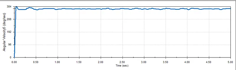
Conclusion: As we can clearly observe that the highest angular velocity is obtained in the second case, where the input is the ring gear, Output is carrier and Sun gear is fixed. While the least angular velocity was found in the First case. This clearly shows how by changing the input and output, the same system can behave differently. The plot indicates that the motion analysis performed is accurate and reliable.
The plot obatined is similar in all the 3 cases , just the magnitude of the angular velocity changes from case to case. we can observe a constant angular velocity almost instantly, this is due to universal gear stationary.