MBD Simulation on a Piston Assembly
Objective:-
To perform Motion Analysis Simulation of a Piston Assembly and analyze the effect of position of wrist pin.
Introduction:-
Piston Assembly
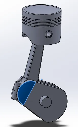
A Piston assembly or more commonly known as piston cylinder assembly is a very basic and widely used application for converting linear motion to rotational motion or vise versa. The most wide spread we know of this mechanism is in IC engines in our cars. It consists of various parts like the piston, crank or crank shaft, gudgeon pin also called wrist pin, connecting rod and end cap, both of which together form and act like a bearing on the crank. A lot of innovation has been done in IC Engines since their inception.
Procedure:-
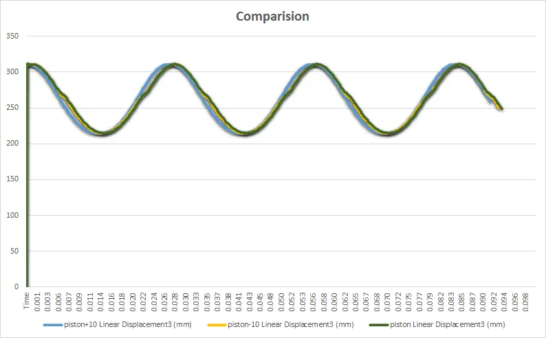
The parts are designed according to the given dimensions and then assembled. Then, three separate assemblies are made, 1 with the wrist pin at the center of the piston, 1 with -10mm offset and 1 with +10mm offset to study the changes or rather the affect of the offset. Piston, Crank, Connnecting rod and its end cap, Wrist pin are designed and then assembled. Motion analysis is carried out of each of the case by providing a RPM of 2000 to the crank and observations are made. Linear displacement of the piston is plotted on graph for each case and then all the 3 graphs are superimposed on each other to derive necessary conclusions. The Frames per second of the simulation are calculated and applied in such a way that the motion simulated is as close to real life as possible in order to obtain the best results and plots.
3D Models
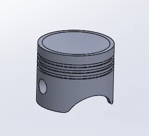
1. Piston Head with oil and compression ring cut outs, wrist pin cut out, and curved top for better combustion.
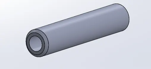
2. Wrist pin or Gudgeon pin that connects the psiton head with the connecting rod.
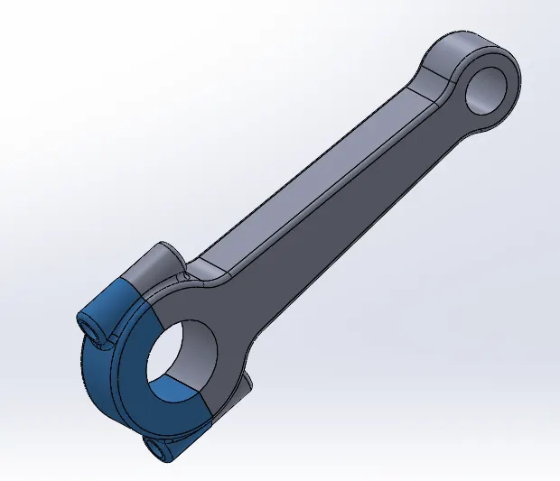
3. Connecting rod with end cap that connects or transmits the force from piston to the crank shaft.
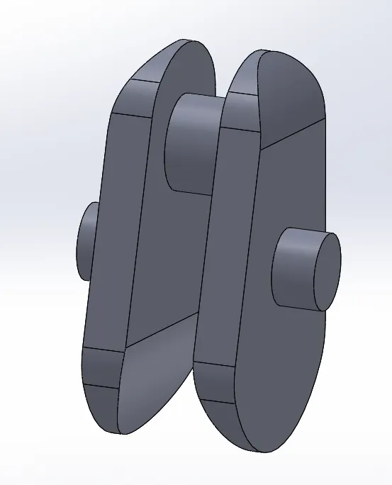
4. Crankshaft or crank
Assembly
No Offset
+10mm offset
-10mm offset
Observations:-
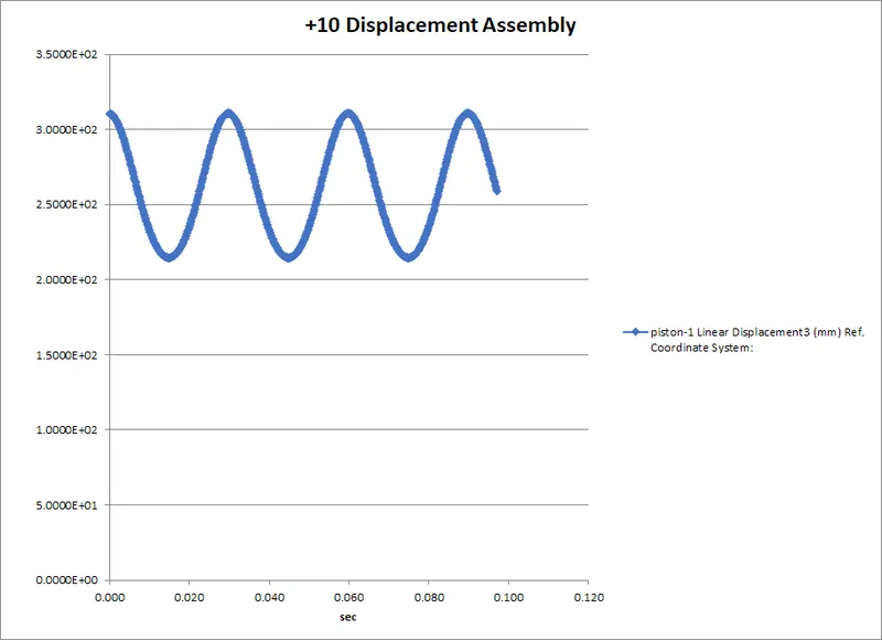
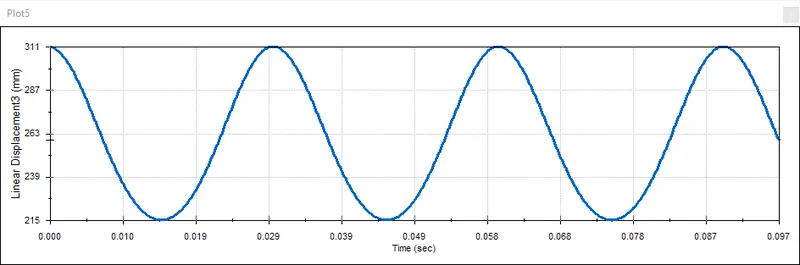
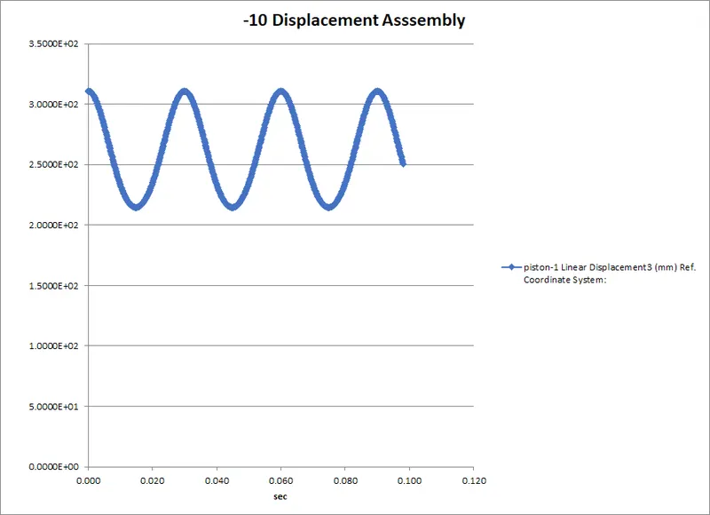
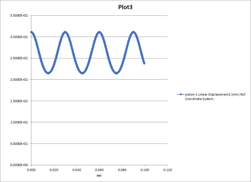
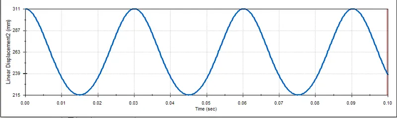
By carrying out the motion analysis and plotting the linear displacement of the piston vs the time, we can see that the motion we simulated is very smooth and hence we can say that we have successfully siulated the piston assembly and we can derive some proper conclusions. We see that the Top Dead Center (TDC) is at 311mm and the Bottom Dead Center is at 215mm, so we can say that the displacement of the piston is roughly 96mm.
Case 1.
Case 2
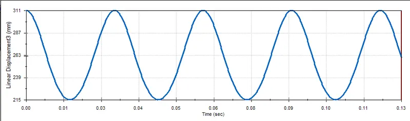
Case 3
Result:-
When we compare all the 3 cases and their results minutely, we see that the maximum dispalcement of 0 or no offset case is 95.95mm, -10mm offset case is 95.77mm, and of the +10mm offset case is 95.76mm. By superimposing all the 3 plots on each other we see that there is only a minor change in the time at which the piston reachs the TDC or BDC. We can also observe from the simulation that there is a change in degree of rotaion of crank at TDC and BDC in all Cases. With 0 offset, The Piston is at TDC when the crank is at 0 degree of rotation, but it is not 0 degree in case of offset.
Conclude:-
We can conclude that there is a very minor difference in the displacement of piston with the offset of wrist pin and the maximum dislplacement is in the case of no offset. We can also conclude that there is a slight delay for the piston to reach TDC, the difference between offset cases is negligible and between offset and no offset is also very insignificant.