MBD Simulation on IC Engine Valve Train
Aim:- MBD Simulation on IC Engine Valve Train.
1. To Obtain the
- Valve Lift
- The contact force between
- Cam and Push Rod
- Pushrod and Rocker Arm
- Rocker Arm and Valve
2. To Explain why the contact force between the Rocker arm and valve varies while measuring with respect to the X direction and measuring with respect to magnitude.
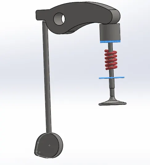
Intro:- The Valve Train is a very important component of an IC Engine. It is the component that controls the flow of fluids to and from the cylinder or cmobustion chamber. A basic valve train consists of 5 components 1. Cam 2. Push-Rod 3. Rocker Arm 4. Valve 5. Tension spring. The are far more components in an actuall valve train in an ic engine, but these are the basic componentes, which are required to simulate the motion of valve. The valve action can be simulated by performing motion body dynamics study on assembly of the valve train. The shape and size of the cam controls the Valve lift as well as the valve timing, which are 2 of the most important functions of a valve train. Without proper valve timimg an IC engine cannot run or ideal, it shuts off. So the valve train is one the most important components of IC Enigne.
Theory:-
Cam
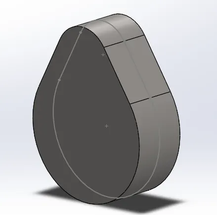
Cam is curve piece of metal which is generally a part of a long shaft, used in valve train linkage to convert the rotary motion of engine to linear motion which is used to drive the valve motion.
Push Rod
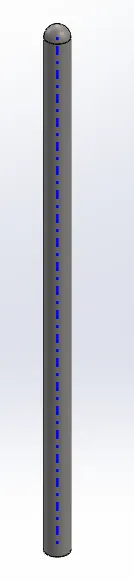
It is a stem like piece of metal which transfers the motion from cam to the rocker arm.
Rocker Arm
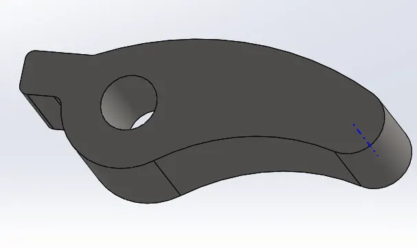
Rocker Arm is an oscillating lever used to transmit the motion from push rod to the valve stem.
Valve
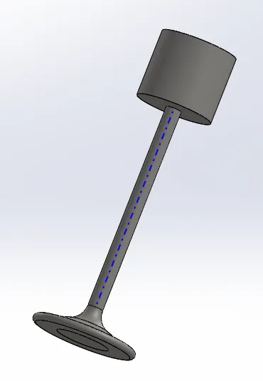
It is a long stem shape component, with a head which is in contact with the rocker arm and a base which is seated on the valve seat inside the combustion chamber. It moves up and down to allow the fluids in and out of the cylinder.
valve Mount
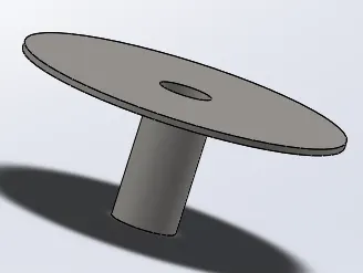
The valve stem is supported by this mount and the tension spring sits in between this mount and the valve head. The spring helps the valve to remain close.
Procedure:
- Model the parts and assemble them in SolidWorks.
- Run the simulation using the below parameters
| Sl.No | CAM Lift (mm) | Speed (RPM) | Material |
| 1 | 3.5 | 1500 | Cast Carbon Steel |
| 2 | 6 | 1500 |
Cast Carbon Steel |
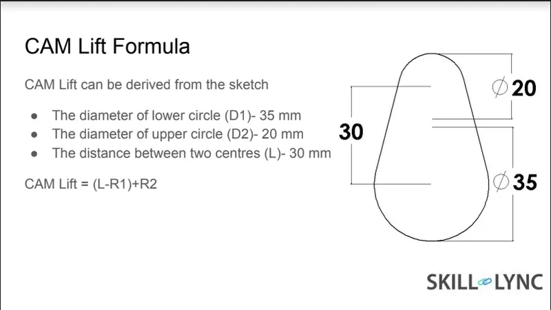
First of all we have to model all the components required for the simulation. after all of the are modelled, an assembly is created, and a motion study is created and a tension spring is added to the assembly.
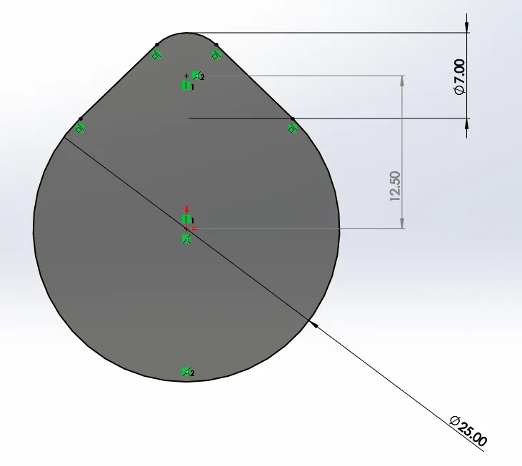
Then two separate cases are created to observe the changes in cam lift. one with cam lift 6mm and one with 3.5mm. I have done that by changing the radius of the smaller circle of the cam. The calculations were as follows:-
cam lift = (L-R1)+R2
1) 6=(12.5-12.5)+R2
R2=6mm
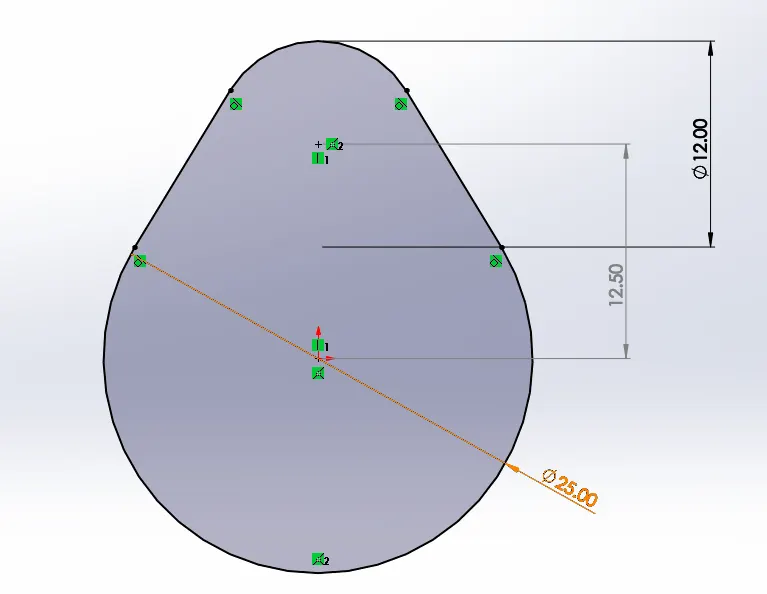
2) 3.5=(12.5-12.5)+R2
R2=3.5mm
Observations:-
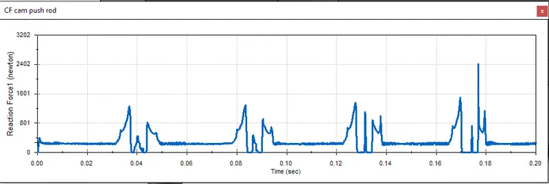
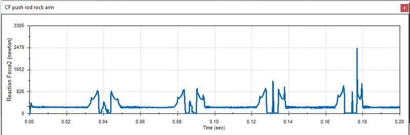
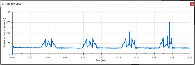
Case 1) CL = 6mm
1. Contact Force between Cam and Push Rod (magnitude)
2. Contact Force between Push Rod and Rocker Arm (magnitude)
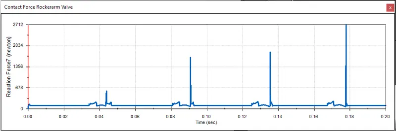
3. Contact Force between Rocker Arm and Valve (magnitude)
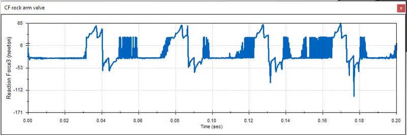
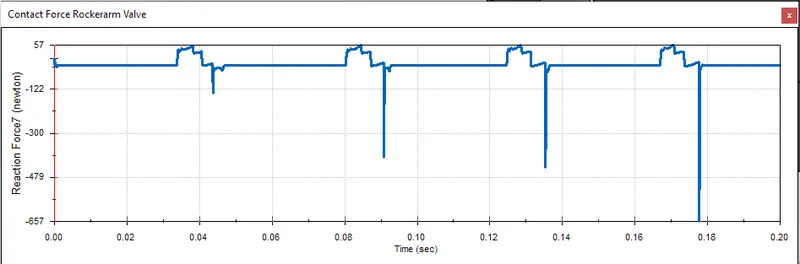
4. Contact Force between Rocker Arm and Valve (x direction)
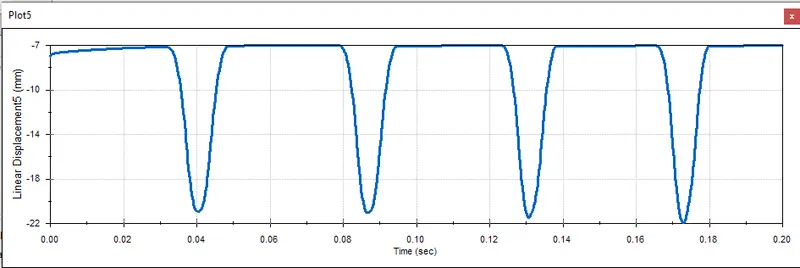
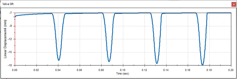
5. Valve Lift
Case 2) CL = 3.5mm
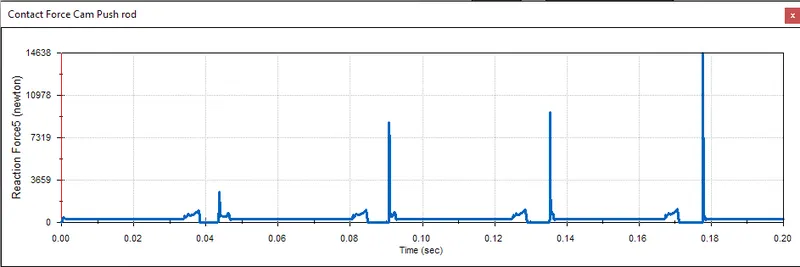
1. Contact Force between Cam and Push Rod (magnitude)
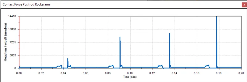
2. Contact Force between Push Rod and Rocker Arm (magnitude)
3. Contact Force between Rocker Arm and Valve (magnitude)
4. Contact Force between Rocker Arm and Valve (x direction)
5. Valve Lift
Result:-
1. The Valve Lift obtained from Case 1) with CL=6mm is approximately 15mm. and Case 2) with CL=3.5mm is approximately 11mm.
2. The contact force between the Rocker arm and valve varies while measuring with respect to the X direction and measuring with respect to magnitude, because in the x direction, only the friction force is applicable that too in the negative x direction, which is why we see negatice value of force in the graph. While on the other hand, when we meausre the magnitude of the contact force, the forces from all the direction are accounted for, which includes the force that is benig transmitted through the linkage, and hence we a get a positive value.
Conclusion:-
When the value of the cam lift is altered, naturally the valve lift is affected. The relation is directly proportional, meaning that with increase in cam lift, valve lift will increase.