Planetary Gear
Aim: To create a CAD model and perform motion analysis on an epicyclic gear train (with 4 planetary gears)
Objectives:
- To calculate the pitch circle diameter and the number of teeth for the planet gear.
- To create the gear assembly and perform motion analsyis for the following three cases
- explain about the Planetary Gear and plots obtained for all the cases
Sl.No Input Output Fixed 1 Sun Gear Carrier Ring Gear 2 Ring Gear Carrier Sun Gear 3 Sun Gear Ring Gear Carrier
Given data:
- Ring Gear
- Module = 2.5 (You must use the metric system in design modeler)
- Number of teeth = 46
- Sun Gear
- Number of teeth = 14
- Input Speed of the Gear = 200 rpm.
- Number of planet gears = 4
Theory:
There are 4 majoy types of gear trains: simples, compunded, reverted and epicyclic gear train. The main purpose of a planetary/epicyclic gear train is to transmit high velocity ratio and torque without a large size/without taking up a lot of space and without a lot of weight.
This is possible first of all due to the design(less size), and higher torque is produced by virtue of the fact that the load is shared among multiple planet gears rather than a pair of meshed gears.
This also increases the net contact area as more number of contacts exists than a parallel-axis gear train, and the load is more evenly distributed.
Common applications include analog wrist watch mechanism and in automatic transmission system in a car (2-3 planetary gear trains are used in conjunction). Other major applications are in turbine engines, electric screwdrivers etc.
Note: The number of planetary gears and the number of teeth are such that the following two equations hold good:
- `(N_s+N_r)/n = 2*(N_s+N_p)/n =`Integer
- `N_r=2N_p+N_s`
- The gear ratio, depending upon the configuration being used can be determined by kinematic analysis. For e.g., if the outer ring gear is fixed, the gear ratio would be G=`(N_r+N_s)/N_s`
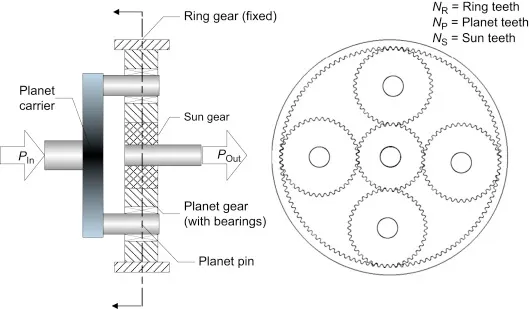
I. Planetary gear calculation:
Diameter of ring gear
Diameter of ring gear= diameter of sun gear + 2 * diamter of planet gear
`D_r=D_s+2*D_p`
=> `D_p=(D_r-D_s)/2`
=>`D_p=`(115-35)*0.5=40mm
Number of teeth of Planet Gear:
Since the module must be same to mesh the gears,
m=D/T
=> T=D/m=40/2.5=16
| Gear | Pitch diameter (mm) | Number of teeth |
| Sun | 35 | 14 |
| Ring | 115 | 46 |
| Planet | 40 | 16 |
II. Creating the gear assembly
- First, based on the dinmensions of the gear ( their repsective pitch circle diameters) and the nominal shaft diameters, the carrier part is modeled.
- Next, in a new assembly file,import the carrier and then using the design library, all the gears are imported and the parameters are given as mentioned in the table above.
- Next, the gears are mated with the carrier in the assembly making sure that the carrier is the first part to be imported (even before the gears) and is constrained to only 1 DOF, rotation about it's own axis.
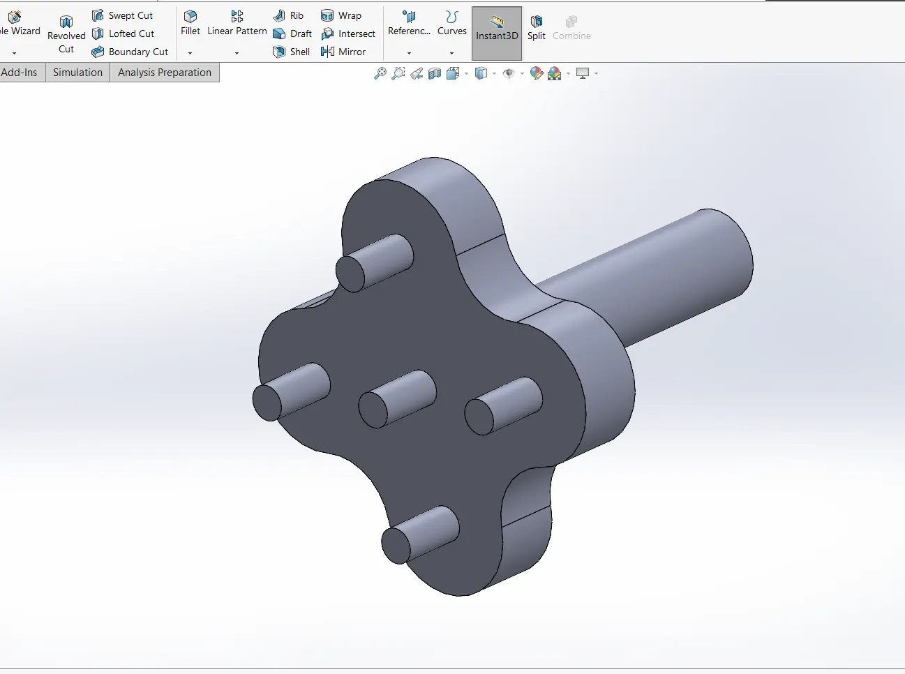
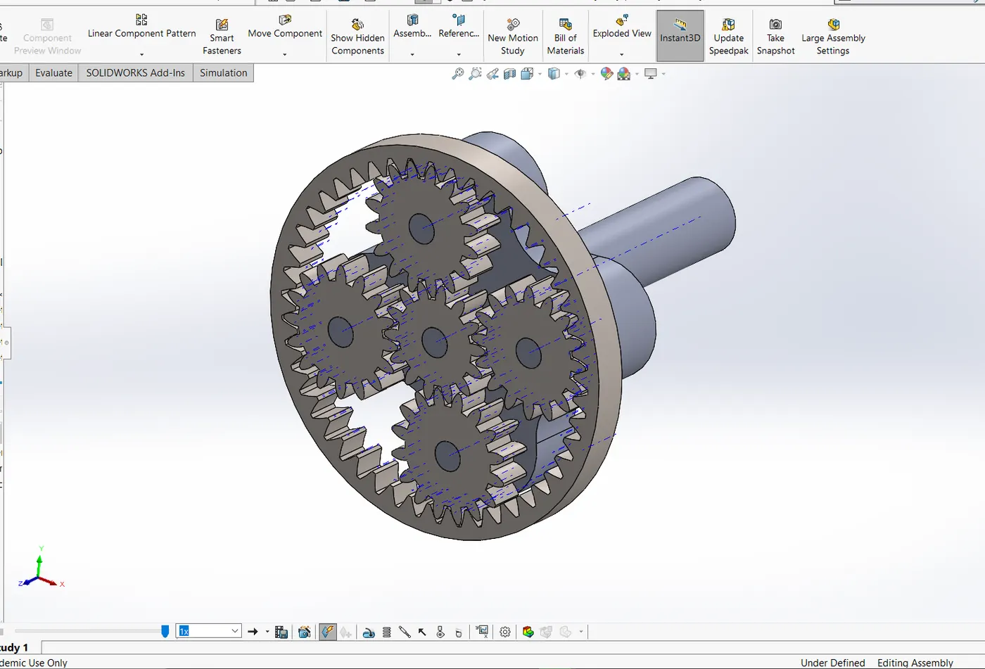
Note: In the model, the nomial shaft diameter taken here is 10mm and the face width of all the gears is 12mm.
III. Motion Analysis Results
Note: Material for all the components is Steel (dry) and all the gears are in contact with one another (gear mate is not used)
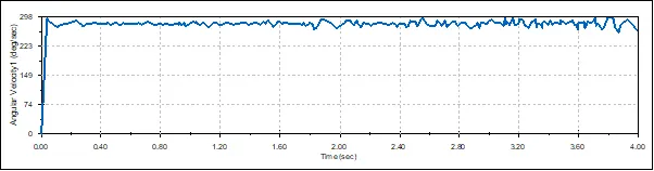
Case1:
Ring gear is fixed. 200rpm input to the Sun gear. The plot for the output rotational speed of the carrier is as follows:
Case2:
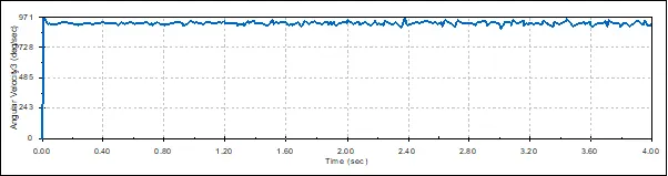
Sun gear is fixed. 200rpm input to the Ring gear. The plot for the output rotational speed of the carrier is as follows:
Case3:
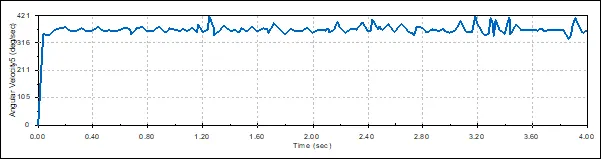
Carrier gear is fixed. 200rpm input to the Sun gear. The plot for the output rotational speed of the Ring gear is as follows:
Observations:
In case one, the sun gear causes the planetary gears to rotate about their own axis and as well as about the central axis of the sun gear and the output is the least of all the cases.
Case two the ring gear rotates such that the motion is transferred to the planetary gears. In particular, this case results in the highest rotational speed output, typically in case of an automatic transmission, this is used for the reverse gear. This is because, if we consider one planetary gear, at the portion where it meshes witht he ring gear, the linear velocities cancel out each other, while at the region mating with the sun gear, they add up, basically the gear reduction principle ( bigger to smaller gear, RPM increases)
Case three has the maximum fluctuation in the output rotational speed, and this cannot be avoided in any of the cases as there will be some ipact and vibration during the operation of the gear/ meeting of the gear teeth.
Conclusion:
The planetary gear assembly is modeled and the motion analysis is performed to observe the performance in different configurations.
References:
https://gfycat.com/gifs/search/planetary+gear
skill-lync.com
https://gearmotions.com/fundamentals-planetary-gear-systems/
https://www.sciencedirect.com/topics/engineering/epicyclic-gears