MBD Simulation on a Piston Assembly
Aim:
To model and assemble different parts of piston in SolidWorks and perform motion analysis
Objectives:
- Model and assemble the parts
- Motion analysis to be carried out in three different conditions:
| Sl.No |
Wrist Pin Offset ` |
Crank Speed (Rpm) |
| 1 | "0" mm | 2000 |
| 2 | 10 mm Positive | 2000 |
| 3 | 10 mm Negative | 2000 |
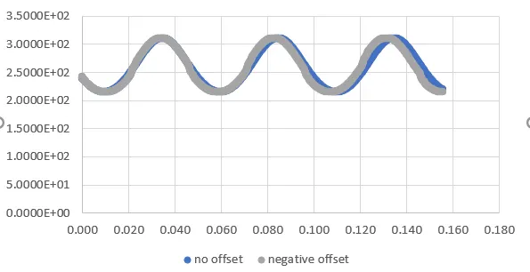
- export the data and overlap the plots
Theory:
Piston's main fucntion is to transfer the force of expanding gas in the cylinder to the crankshaft throught the connecting rod.
It typically has two compression ring, mainly for the prevention of gas escape throught the cylinder wall and piston clearance, and a oil control ring, to create a thin film from the oil sprayed on to the cylinder walls from the con rod holes or jets in the crank case.(the slots on the piston are for these rings)
Wrist/Gudgeon pin is the connection between the piston and the con rod small end, about which it can pivot. The wrist pin mat be offset to minimize the damage to the cylinder wall (due to piston slap caused by the lateral movement of the piston)
The connecting rod transfers the reciprocating motion of the piston to rotary morion of the crank, it undergoes bending and buckling and hence it needs to be strong and based on these stress considerations, it usually has an I-shaped cross section(as it faacilitates maximum area moment with reduced weight)
The big end of the con rod is attached to the crank (using an end cap and bolts), which rotates the crankshaft, being an integral part of it.
Procedure:
1. Modelling and Assembly:
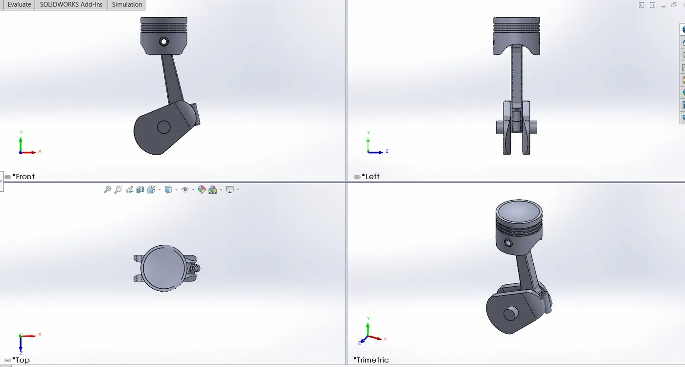
- For each of the parts, the 2D cross section sketch is made and either extruced and revolved and the process is repeated as and when necessary to get the respective part files.
- In a new assembly file, these parts are inserted, the crank is fixed wrt to the global planes and the other parts and mated wrt crank
2. Motion Analysis:
- 1200 rpm motor is set to the crank, clockwise and gravity is set in the -Y direction.
- Contact is established between the all the parts in pairs.
- precise contact is turned on and the animation is set to 7200fps.
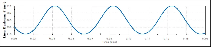
- The simulation is stopped after 3 rotations of the crank to plot the results
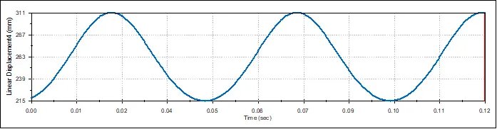
- Linear displacement of the top of the piston is plotted over time.
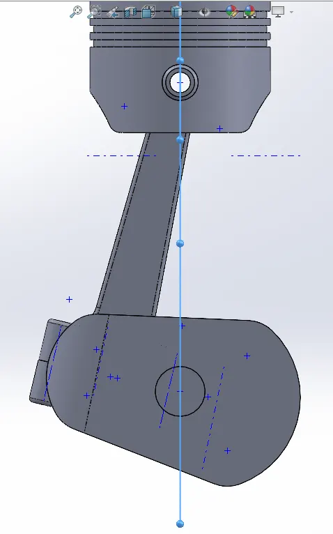
Case1: No offset (axis of wrist pin is collinear with the axis of the crank)
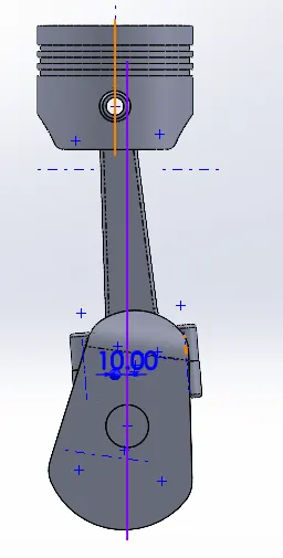
Case2: 10 mm Positive offset
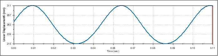
case3: 10mm negative offset
The direction of the offset is reversed and a new simulation gives the plot below:
3. Overlapped plot of negative offest and zero offset:
Conclusion:
The displacement of the piston remains the same in all the three cases but the use of offset is that it reduces the wear due to piston slap and hence it also improves the performance of the engine (speed may increase)
References: