MBD Simulation on IC Engine Valve Train
Aim: To design the valve mechanism assembly and perform motion analysis to obtain valve lift and contact forces for different cam lifts
Objectives:
- Model the parts and assemble them in SolidWorks.
- Run the simulation using the below parameters
| Sl.No | CAM Lift (mm) | Speed (RPM) | Material |
| 1 | 6 | 1500 | Cast Carbon Steel |
| 2 | 3.5 | 1500 |
Cast Carbon Steel |
3. Generate plots for:
- Valve Lift.
- The contact force between
- Cam and Push Rod
- Pushrod and Rocker Arm
- Rocker Arm and Valve
Theory:
There are different types of valve mechanisms based on the location of cam shaft and the types linkages used(tappets,spring,etc)
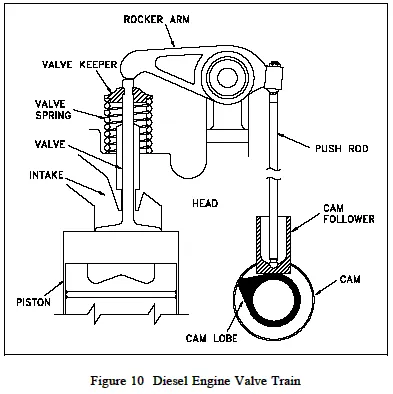
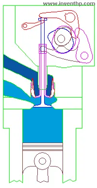
Here, a simple spring return valve mechanism with the cam on the lower side is designed to operate the valve.
A cam is an egg-shaped eccentric lobe, typically a few of these are place on a long bar (forming the cam shaft), one for each valve in the enigine. As the cam shaft is rotated, the push rod is forced up and down due to the profile of the cam.
The push rod and rocker arm transfer the reciprocating motion to the valves, opening and closing them, at the right time.
The retraction of the valve is due to the spring force and depends on the stiffness and initial compression of the spring.
Procedure:
- The 2D-cross sections of the cam, push rod, rocker arm, valve stem and the valve are made using the 2D drafts, and are modelled using the extrude and revolve cammands.
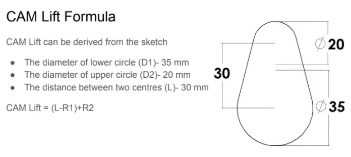
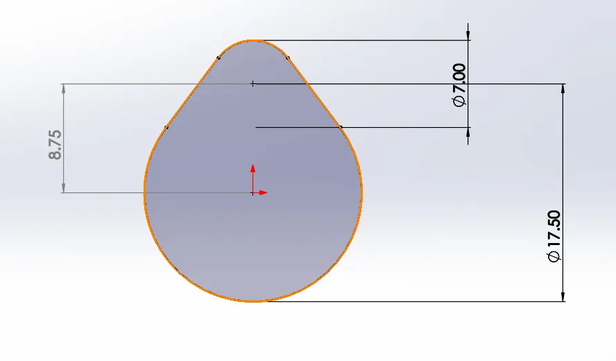
- For the two different cases of cam lifts, different cams are designed based in the following formula:
- The parts are mated wrt the cam and using the "move component" cammand and 'physical dynamics', the assembly is adjusted to proper contact
- Motion study is perfomed with the motor @1500rpm, and establishing contact between the parts in pair, and assign the same material to all of them.
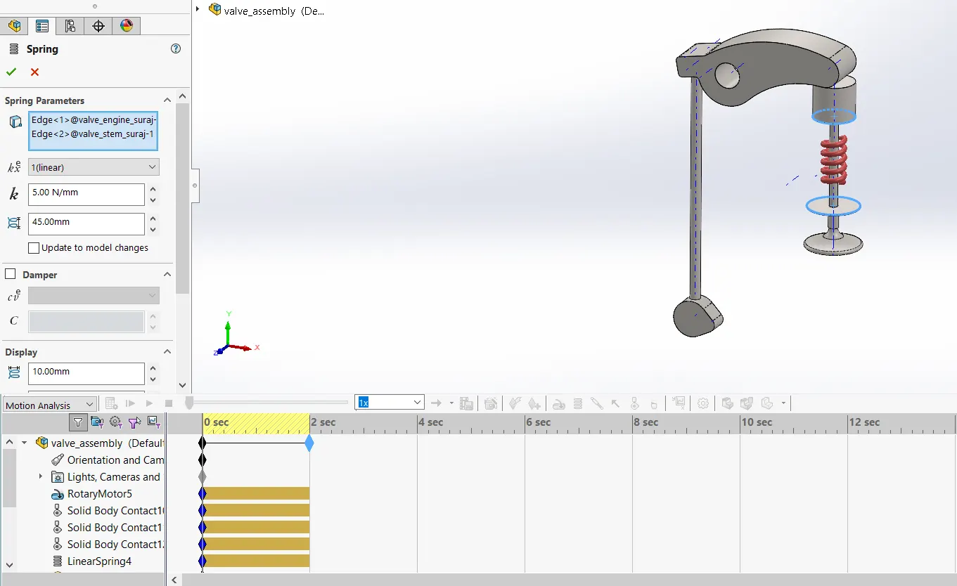
- Considering the initial compression of 10mm, the free length is set to 45mm(10+35mm) and the stiffness is set to 5N/mm.
- The simulation is ran for 2 seconds with precise contact and 1500 fps.
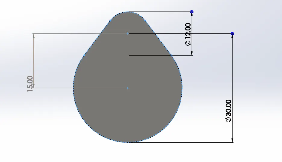
Case 1: Cam Lift =6mm
Cam Lift = (L-R1)+R2=(15-15)+6=6mm
Case 2: Cam Lift =3.5mm
Cam Lift = (L-R1)+R2=(8.75-8.75)+3.5=3.5mm
Results:
Case 1: CAM lift = 6 mm
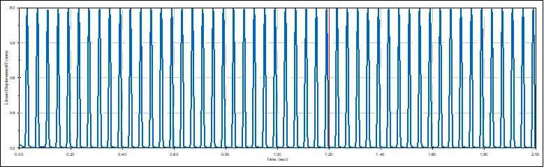
1. Valve lift:
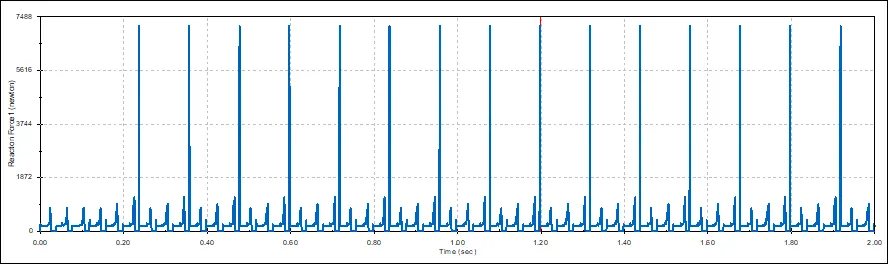
2. Contact force between Cam and Push rod:
3. Contact force between Push rod and Rocker arm:
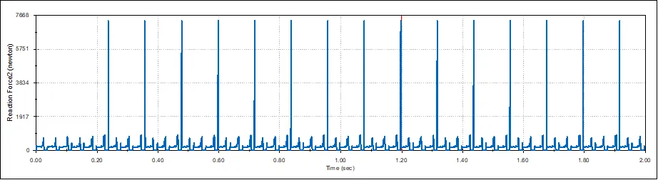
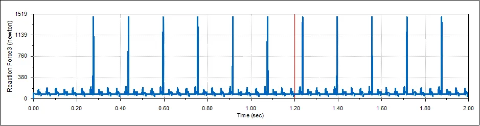
4. Contact force between Rocker arm and valve:
Case 1: CAM lift = 3.5mm
1. Valve lift:
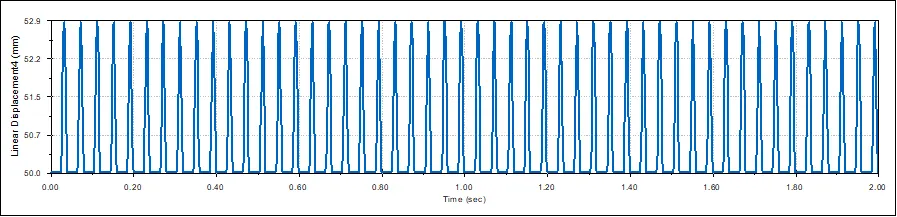
2. Contact force between Cam and Push rod:
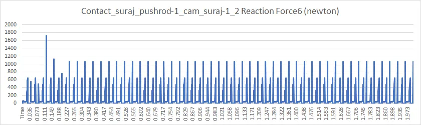
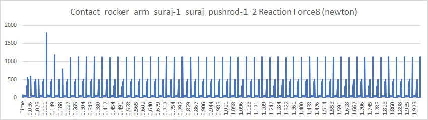
3. Contact force between Push rod and Rocker arm:
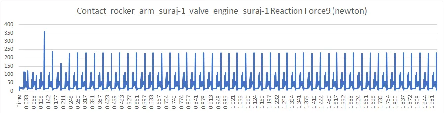
4. Contact force between Rocker arm and valve:
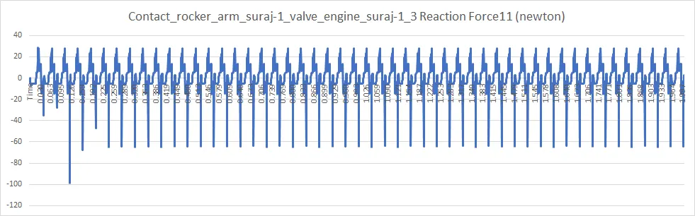
In X-direction:
Conclusion:
Firstly, the magnitude of the contact force between the rocker arm and valve is the net force, and in x direction, it is negative because each time the rocker arm pushes the valve downwards, when the pushrod is in contact with the nose portion of the cam, the x component is in the negative direction
And the valve lift is about 8mm (for 6mm cam lift) and about 3mm ( for 3.5mm cam lift)
References:
https://www.inventhp.com/Other_Applications_Uniportvalve.html
https://www.engineersedge.com/power_transmission/diesel_timing_gears_camshaft.htm