Internal Geneva Mechanism
Aim: To create a model of an Internal Geneva Mechanism and perfom its motion analysis.
Objectives:
- Create part models of the driver and driven components of the Mechanism using Solidworks
- To assemble them and run motion analysis by giving the driver component 10 rpm and 20rpm rotation speeds.
- Plots for the contact force, angular velocity and angular displacement (with and without precision contact)
Theory:
- The Geneva mechanism essentially transforms a continuous rotational motion into an intermittent rotary motion, i.e, alternate periods of motion and rest with no reversal of direction of rotation.
- The mechanism has a driver and driven component. The driver has a pin that goes through the slot in the driven to rotates it through surface contact.
- There are different types of this mechanism such as external, internal ans spherical. The simplest of which, the external geneva mechanism is shown below, where the number of slots on the driven influences the rotation angle and number of advances. Basically, if there are 4 slots, the driven will move 4 times to complete a rotation, hence 'intermittent', and each time it roates an angle of 90 degrees.
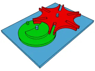
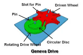
- The applications of such a motion include watches, indexing (say in case of gear cutting) currency note counting machines, Plotters, movie projectors, turretof a CNC machine, between steering wheel and propeller shaft etc
- Interestingly enough, it can be optimized to be used as a type of an engine, with the pins and slots for combustion chambers, essentially converting linear motion into rotary morion which can power automobiles. More on this in the research paper on the same under references.
Internal Geneva Mechanism:
The peculiar thing about a typical 'internal' geneva mechanism is that unlinke the external variant, the driver component has to roate an angle less than 180 deg for one advance of the driven. But in this case, impact while entering the slot seems higher which can be reduced by operating at a lower speed so that the contact force of the impact is reduced, which is demostrated in this study.
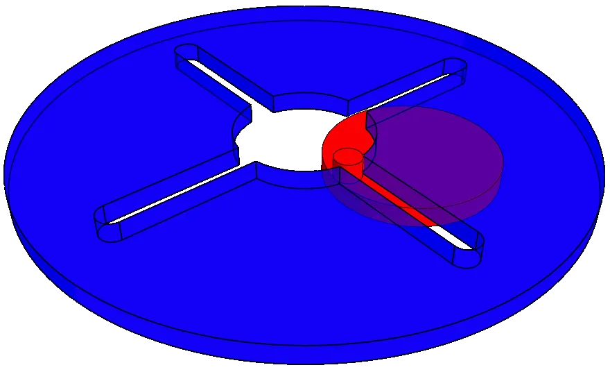
Model:
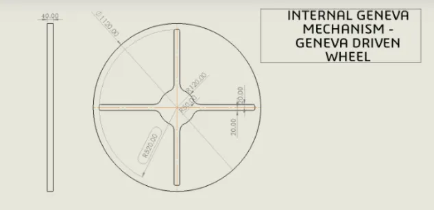
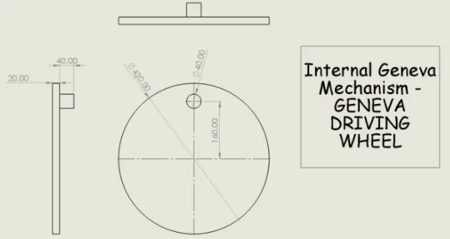
The driver and driven parts are made using the following 2D drafts, by creating a sketch in the top plane and extruding it.
An additional sketch for the path of travel of the pin/ positioning it is made for reference during assembly.
Assembly:
First, the driver part is inserted and fixed on the top plane of assembly.
Then, its axis is constrainted to the intersection of the front and right planes of the assembly so that it has only one degree of freedom(DOF), rotation about its own axis.
Next, the driven part is introduced and its central axis is made coincident with the right plane, and mated withthe driver's top plane (with clearance) so it has two DOF, rotation and translation along the right plane.
Finally, the reference sketch is used to position the pin and measure the center to center distance between the driver and the driven, and that distance mate is applied, to give a final part as shown.
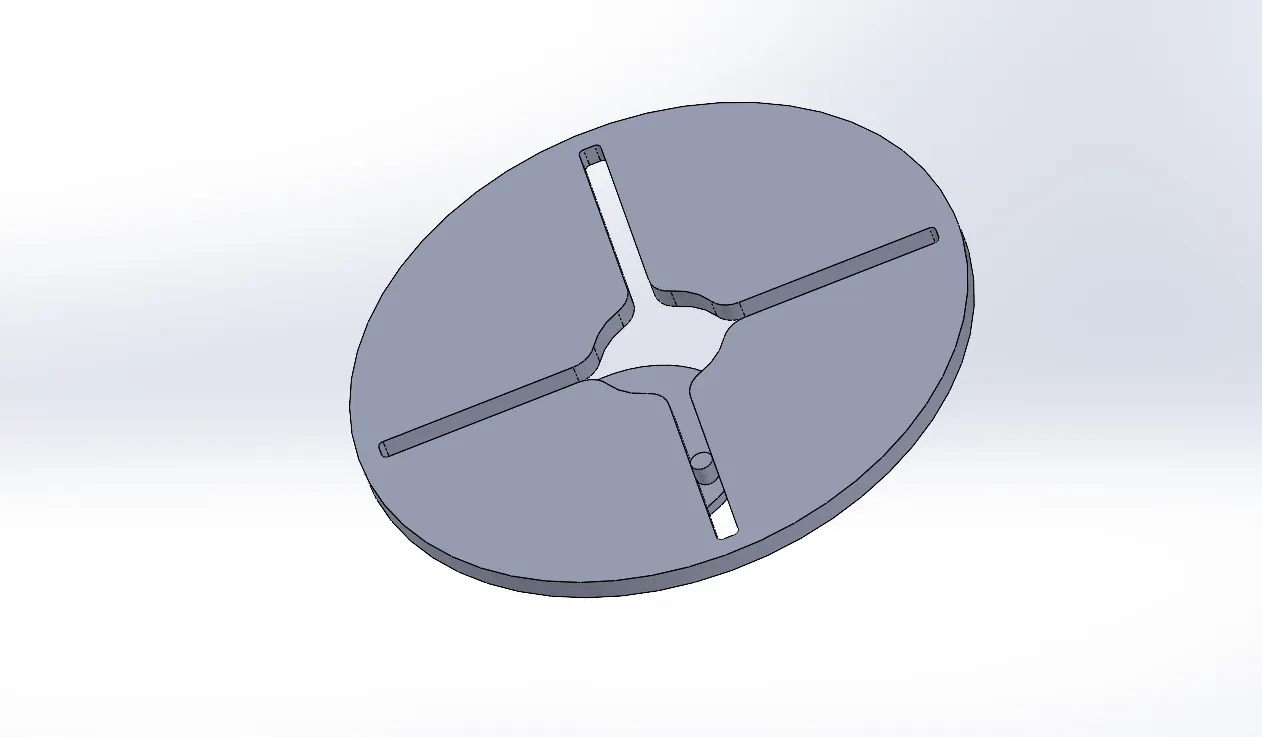
(the reference mate is later supressed)
Motion Analysis:
1. Contact betwwen the parts is established, with necessary material applied.
2. Driver is given the desired rotational speed
I) At 10 RPM:
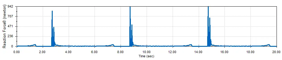
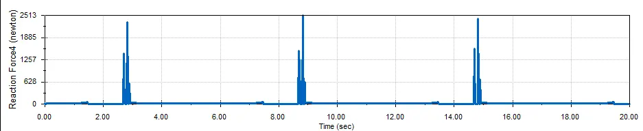
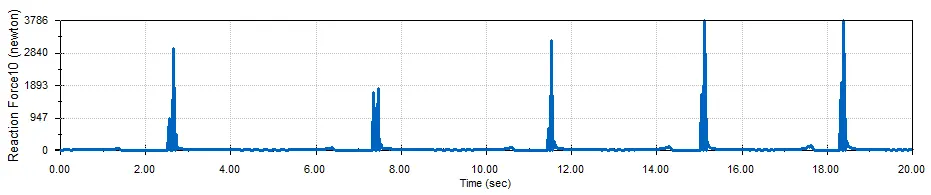
1. Contact force with and without precise contact (60fps):
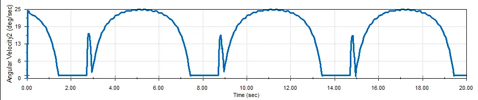
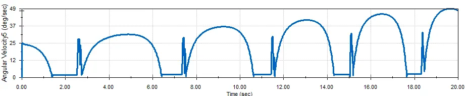
2. Angular velocity:
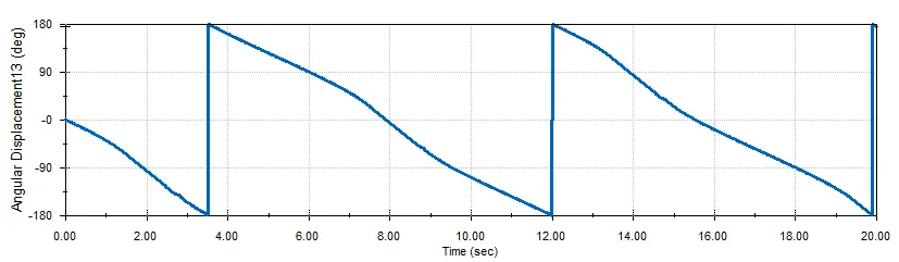
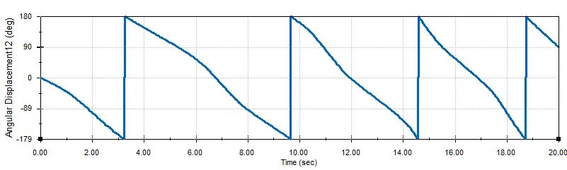
3. Angular displacement:
II) At 20 RPM:
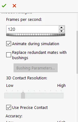
Snippet for precise contact:
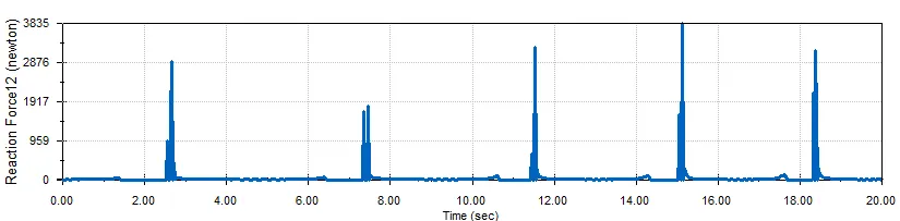
1. Contact force with and without precise contact (120fps):
2. Angular velocity:
3. Angular displacement:
Errors:
Initially, there was not enough clearance between the driver and the driven for free relative motion and hence the motion was not smooth. Upon fixing that, the simulation of the mechanism worked fine.
Exporting to excel:
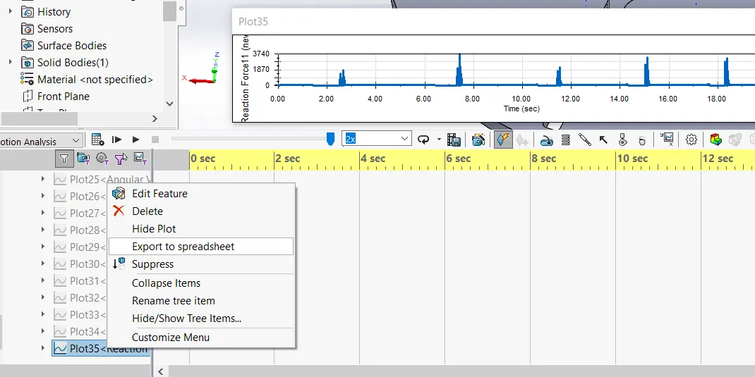
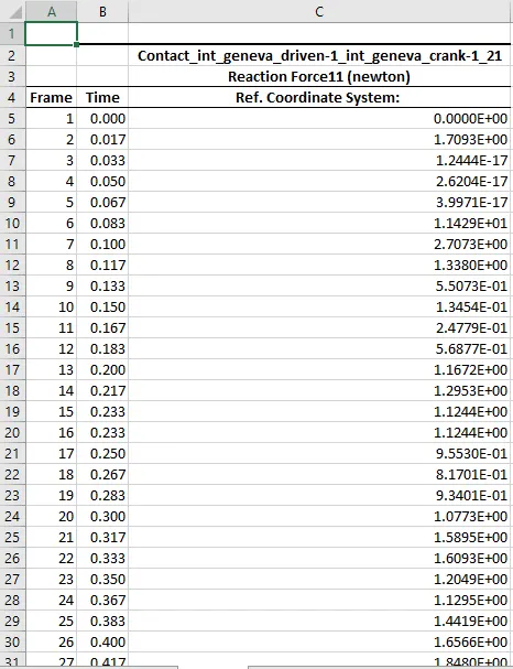
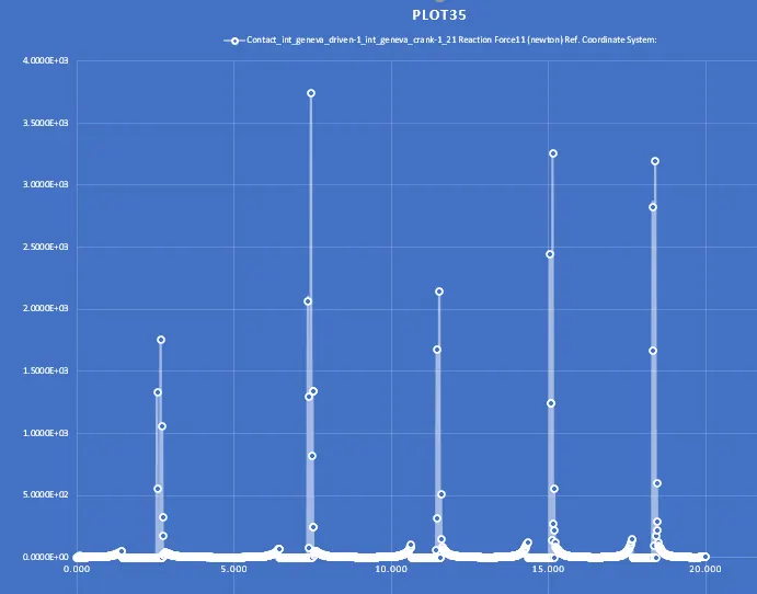
The Plot and data generated in the excel file:
Result:
(10 rpm)
Conclusion:
When the pin enters the slot, there is a jerk and this impact cannot be avoided but a lower RPM gives lesser impact force, at least initially.
Precison contact gives more accurate results and smoother plots as the resolution is increased.
The angular velocity of the driven wheel increases with the rotation speed of the driver component.
The angular displacement shows a pattern
References:
help.solidworks.com
commons.wikimedia.org