Planetary Gear
AIM – To design the planetary gear and to done it simulation
INTRODUCTION- An epicyclic gear train is called planetary gear it consist of a carrier, ring gear
Sun gear and planet gears. In Epicyclic gearing or planetary gear set is a gear system consisting of
one or more outer, or planet, gears or pinions, which are revolving about a central sun gear or sun
wheel. Generally, the planet gears are mounted on a movable arm or carrier, which itself may rotate
relative to the sun gear.
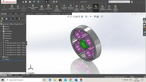
PLANETARY GEAR SET
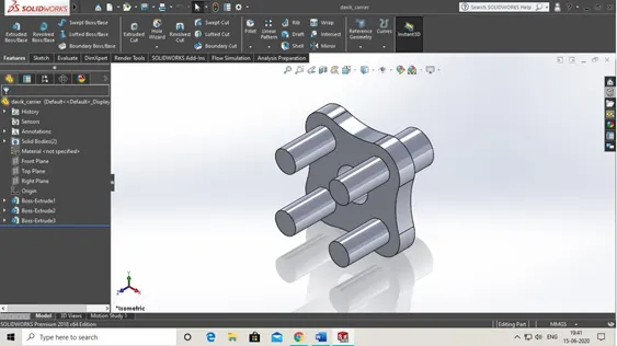
CARRIER
THEORY
As other types of epicyclic gear train or planetary gear works our planetary gear also works in the
same way. As in our planetary gear have consist of 4 planetary gears, sun gear, ring gear and
carrier. So how it works?
When the ring gear is fix and we transmit torque to the sun gear then this torque transmitted to the
Planet gears expect when ring gear is fix this lead to planet gears go all around the ring gear
Periphery and when this type of motion of planet gear is their then our carrier is rotate. So this is
How our mechanism works.
Some assumption are given before we doing our planetary gear motion analysis
|
Sl.No |
Input |
Output |
Fixed |
|
1 |
Sun Gear |
Carrier |
Ring Gear |
|
2 |
Ring Gear |
Carrier |
Sun Gear |
|
3 |
Sun Gear |
Ring Gear |
Carrier |
So by according to this assumption we do our motion analysis.
So now are the following steps to make planetary gear system
- Open soildworks and click new and then select assembly.
- Then go on design library and select toolbox and from then you have to select ansi metric.
- From ansi metric you have to select power transmission
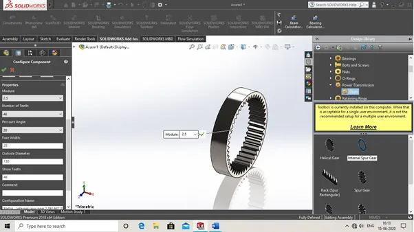
4. From power transmission you have to select then internal spur gear. And then click ok. Like shown in img.
Ring gear calculation
Module = 2.5
No of teeth = 46
PCD = 46*2.5
115mm
Face width=25mm
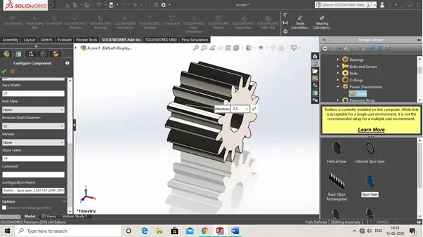
5. Then we need a sun gear so we again on ansi metric and then select power transmission and from that select spur gear.
Calculation of sun gear
Module= 2.5
No of teeth= 14
PCD= 14*2.5
35mm
Speed of input(sun) gear= 200rpm
6. Now we need 4 planet gears and we follow the same procedure to select the spur gear.
Calculation of planetary gear
We know that
Module= 2.5
Here formula to calculate the planet gear pitch circle diameter
PCD of planet gear= PCD of ring gear-PCD of sun gear/2
115-35/2
= 40mm
No of teeth = 16
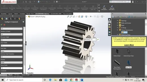
7. Then we have to assemble all planetary gears to do that that first we made sketch s that we can assemble all gears to its particular position.
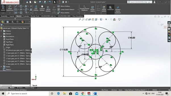
8. Then we have to make carrier to do first we made sketch of it. Then extrude by to our perspective.
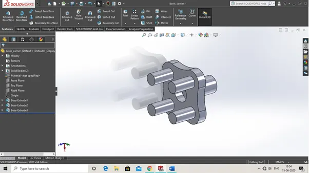
Now all the parts are made and we just get head upto assembly.
1. Click on new and then select assembly
2. After first we open our planetary gears and our carrier
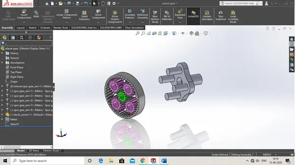
3. Then first fix our planetary gear set and carrier set as a float.
4. Then we apply concentric mate relation between sun gear and carrier shaft.
5.Then we apply coincident mate between planet gears and carrier planet gear shafts.
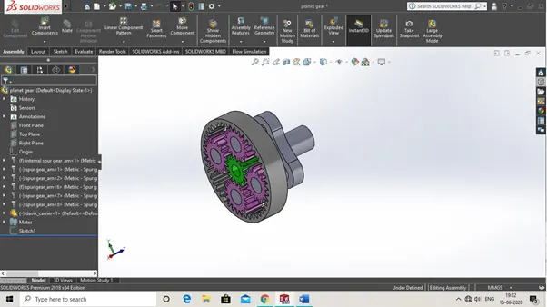
6.Then we make final assembly as shown in figure.
Now we have to come to motion analysis part of planetary set
1. As first we have to select soildworks motion
2. Then go to motion study
3. Then select axis of sun gear for motor and type it 200 rpm as constant speed.
4. Then select soild body contact between carrier and gears
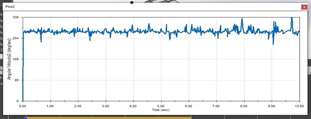
CASE 1 – INPUT OUTPUT FIXED
SUN GEAR CARRIER RING GEAR
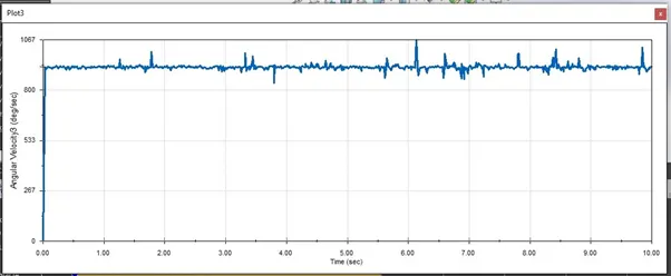
CASE 2 – INPUT OUTPUT FIXED
RING GEAR CARRIER SUN GEAR
CASE 3 - – INPUT OUTPUT FIXED
SUN GEAR RING GEAR CARRIER
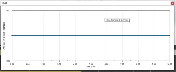
These are all above plots of angular velocity of planetary gear.
RESULTS
As we know
W = 2*3.14*N/60 As N = 200 rpm
2*3.14*200/ 60 = 20.93 rad/sec
CASE 1 – Angular velocity
As V= rw W = 20.93 rad/sec
V = 15*20 r = 15mm
V = 300 deg/sec
So by theory the angular velocity is 300 deg/sec and by motion analysis the plot angular velocity obtained is obtained between 224 to 338 deg/sec.
Here, time(T) = 10 sec
So, W= dtheta/dt dt = 10 sec and W = 20.93 rad/sec
dtheta = 20.93*10 = 209.3 degree
Means that completion of 10 sec will make shaft of 209.3-degree angle.
CASE 2- Obtained same result is above
CASE 3 – Angular velocity
As V= rw W = 20.93 rad/sec
V = 65*20 r = 65mm
V = 1300 deg/sec
So by theory the angular velocity is 1300 deg/sec and by motion analysis the plot angular velocity obtained is 1200 deg/sec.
Here, time(T) = 10 sec
So W= dtheta/dt dt = 10 sec and W = 20.93 rad/sec
dtheta = 20.93*10 = 209.3 degree
Means that completion of 10 sec will make shaft of 209.3-degree angle.
CONCLUSION
we can use planetary gear in automatic transmission it is helpful when we need quick power from engine.
To see motion analysis planetary gear of CASE 1,CASE2,CASE3 click that link down below.