MBD Simulation on IC Engine Valve Train
AIM -MBD Simulation on IC Engine Valve Train
INTRODUCTION – The valve train consists of the valves and a type of mechanism that is consist of opening and closing system. The opening and closing system is workable by the camshaft without the camshaft mechanism don’t work properly on time.
Most modern engines of valve system have what are called overhead cams. This means that the camshaft is located above the valves. The cams on the shaft is responsible to valve open up and closing up.
CAM
PUSH ROD
VALVE
VALVE MOUNT
ROCKER ARM
THEORY
As in our valve system the following components are their as we discuseed in our introduction part. The working of valve train is usual as we discussed. But what we are modify in our project is make all components are to material of cast carbon steel as some assumption of it. For motion analysis we set are frames to 7200 per second and done our motion analysis to 1500 rpm we calculate some contact and linear displacement plots also.
Let’s see how to make this model.
So, to make IC engine valve train there are following steps
So, let’s see
CAM
- Open new window on soildworks as a part.
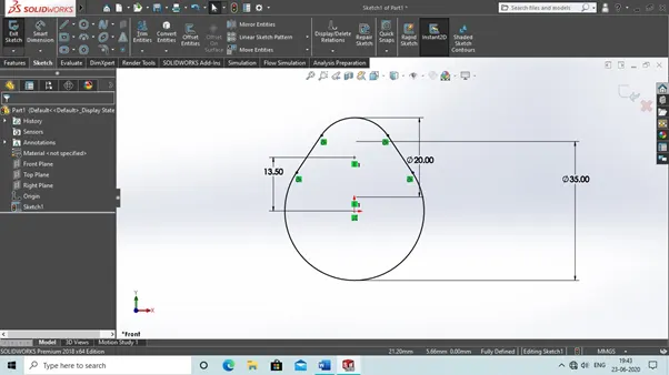
- Then select front plane and make sketch which is shown below.
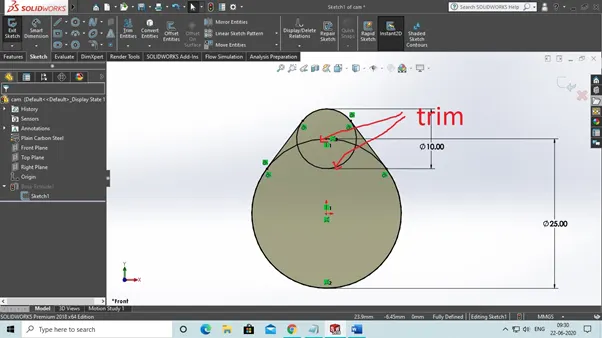
3. Trim the part that is shown by red arrow and then final sketch look like this.
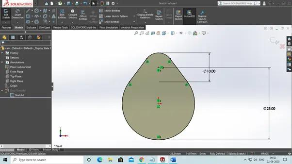
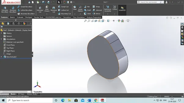
4. Then extrude this sketch as mid plane and upto 10mm.
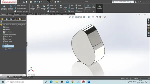
Now save this part as cam.
ROCKER ARM
- Open new window and open as part
- Then click on front plane and make sketch which is seen below.
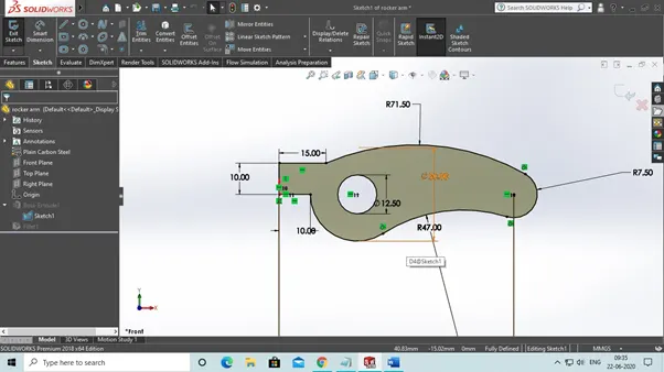
3. The extrude this sketch as mid plane upto 20mm.
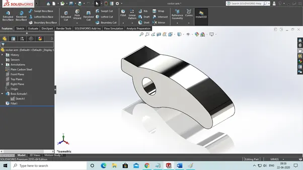
Now save this part as rocker arm.
PUSH ROD
- Open new window in soildworks as a part.
- Then click on front plane and made this sketch as seen down below.
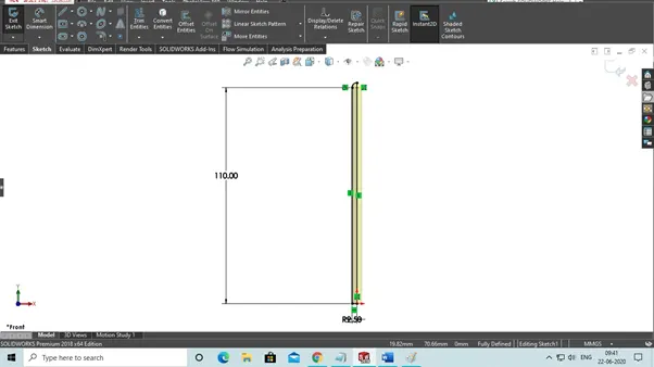
3. Then revolve this sketch about the axis.
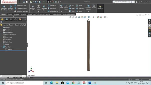
Now save this part as push rod.
VALVE
- Open new window in soildworks as part.
- Then click on front plane and made this sketch which is seen below.
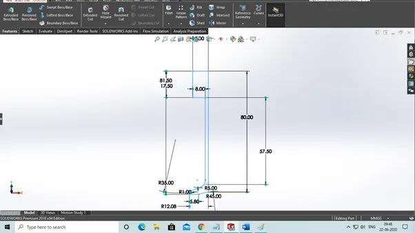
3. Then revolve this sketch to its axis.
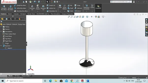
Now this save part as valve.
VALVE MOUNT
- Open new window in soildworks as part.
- Then click on front plane and made this sketch as seen below.
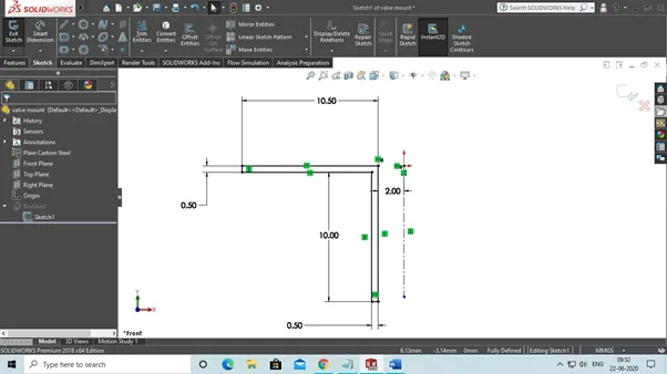
3. Then revolve about its particular axis.
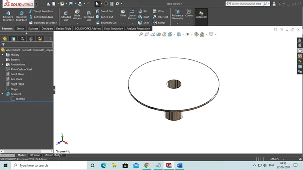
Now save this part as a valve mount.
ASSEMBLY
- Open new window in soildworks as a assembly option
- Insert all valve train parts
Cam
Push rod
Rocker arm
Valve
Valve mount
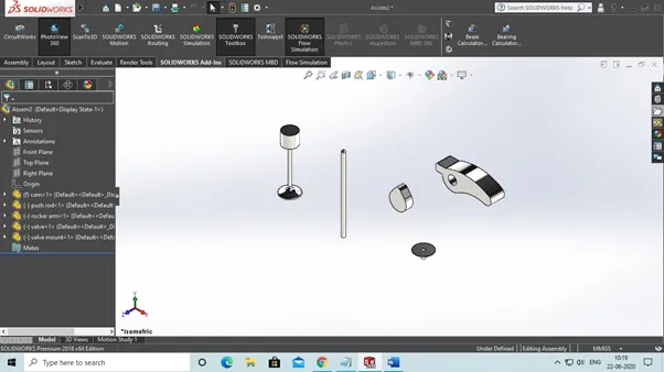
3. Then first select rocker arm temporary axis and then mate with top plane
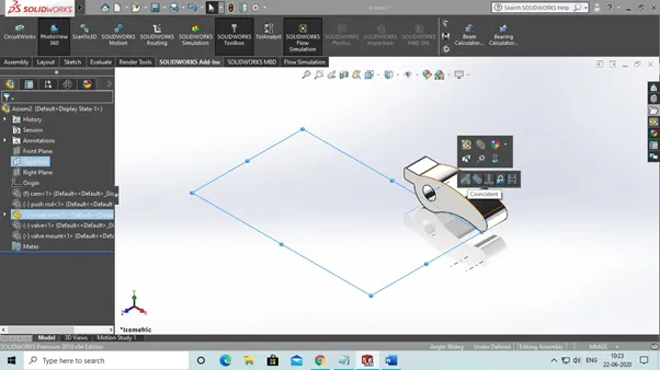
4. Then mate with front plane of assembly with rocker arm front plane.
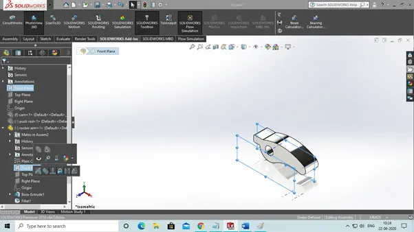
5. Then mate right plane assembly with rocker arm axis.
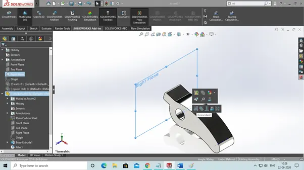
6. Then mate cam front plane with assembly front plane.
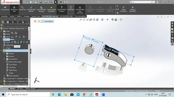
7. Then mate push rod axis with assembly front plane.
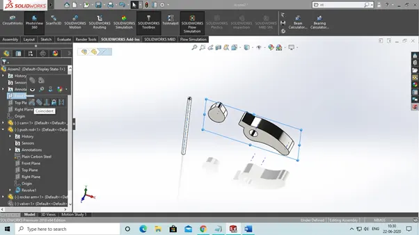
8. Then mate valve axis with assembly front plane.
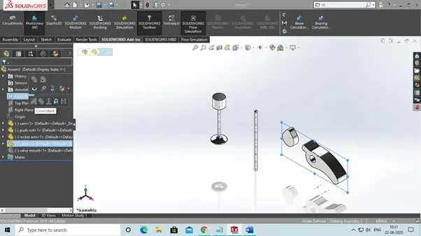
9. Then mate valve mount with assembly front plane.
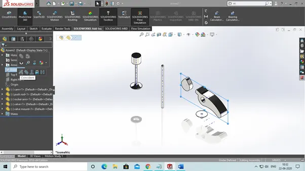
10. Then select push rod axis and assembly right plane and make distance mate between them of 20mm.
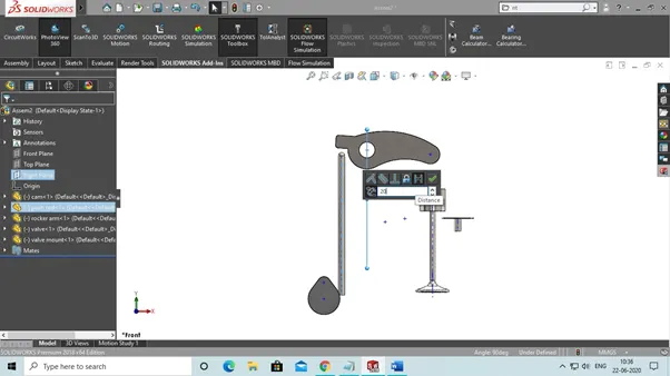
11. Then select cam axis and assembly right plane and make distance mate between of 20mm.
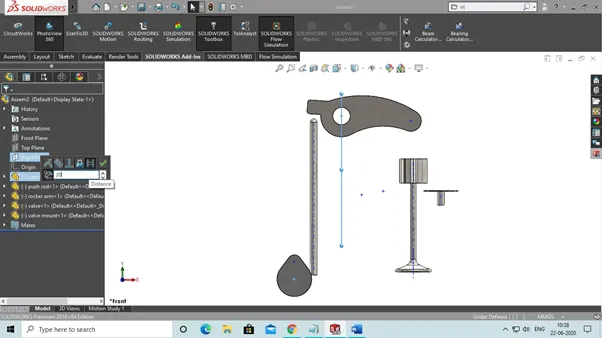
12. And then select cam axis and assembly top plane and make distance mate between of 125mm.
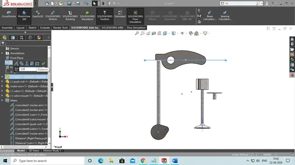
13. Make sure push rod touch the rocker arm.
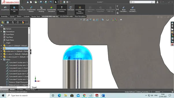
14. Make sure push rod touch the cam also.
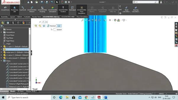
15. Then we choose valve axis and valve mount axis and make between coincident mate.
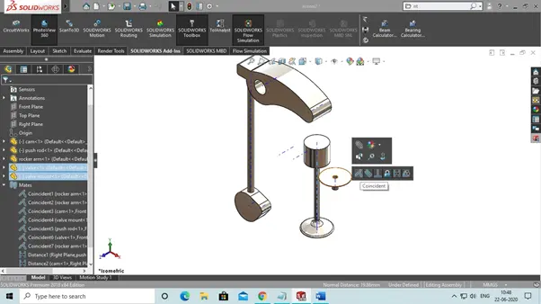
16. Then select the valve mount axis and right plane of assembly and make distance mate between them of 50mm.
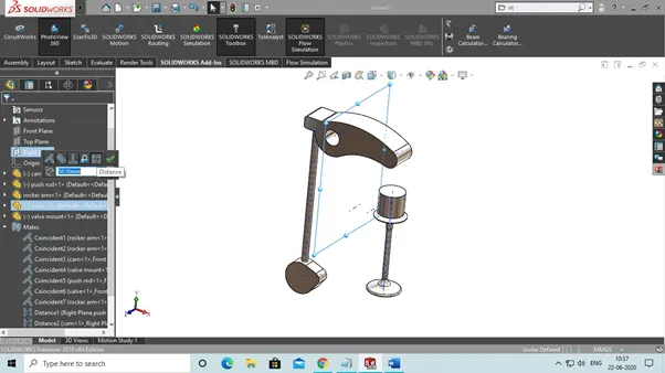
17. Then select valve mount upper face and assembly top plane and make distance mate of 60mm.
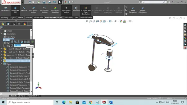
18. Then the final assembly look like this and hide temporary axis.
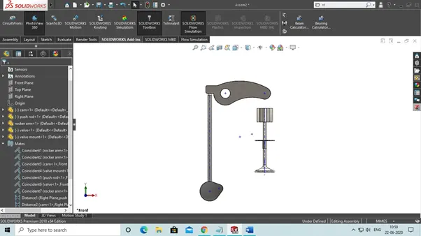
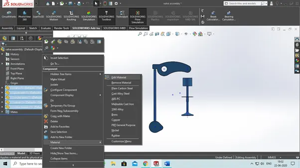
19. Now assembly is done so we add material to our assembly parts to do that select all parts and right click on that and select material>>edit material and then choose cast carbon steel.
REPORT ON MOTION ANALYSIS
Take frames 7200 per secon for smooth analysis with precise point to be check.
And take spring length to be 45mm and spring constant(k) = 10 n/mm
Now we before we move to our motion analysis part there is assumption given
|
Sl .no |
CAM LIFT (mm) |
Speed (RPM) |
MATERIAL |
|
1. |
3.5 |
1500 |
CAST CARBON STEEL |
|
2. |
6 |
1500 |
CAST CARBON STEEL |
So here our first case
CAM LIFT = 3.5mm
R1 = 10MM
R2 = 17.5
So by formula of cam lift
CAM LIFT = L – R1 +R2
SO,
L = 11mm
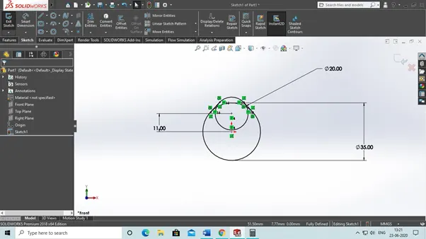
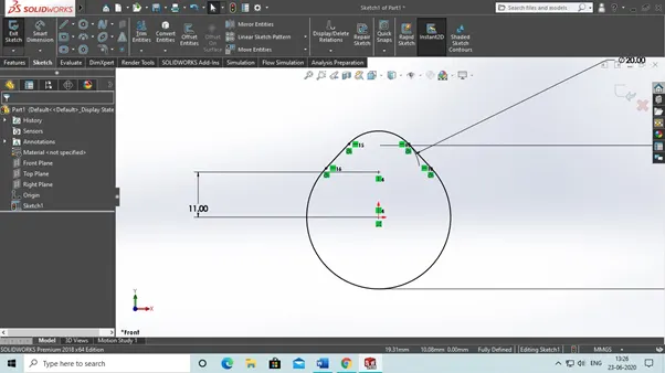
After trimming it looks likes.
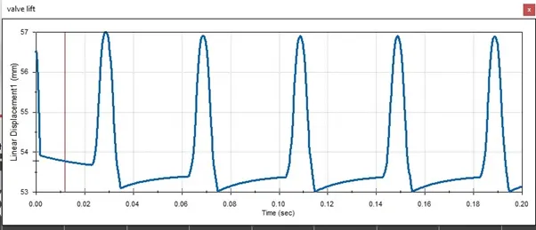
Valve lift
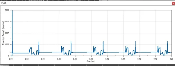
Contact force between cam and push rod
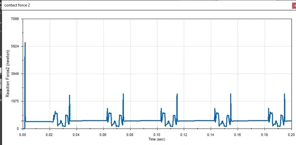
Contact force between rocker arm and push rod
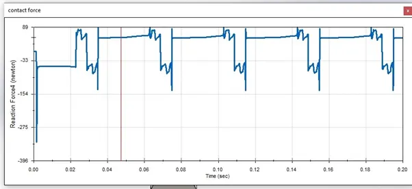
Contact force between rocker arm and valve magnitude
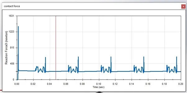
Contact force in x direction between rocker arm and valve.
CASE 2
CAM LIFT = 6mm
Cam lift = 6mm
R1 = 10MM
R2 = 17.5
So by formula of cam lift
CAM LIFT = L – R1 +R2
L= 13.5mm
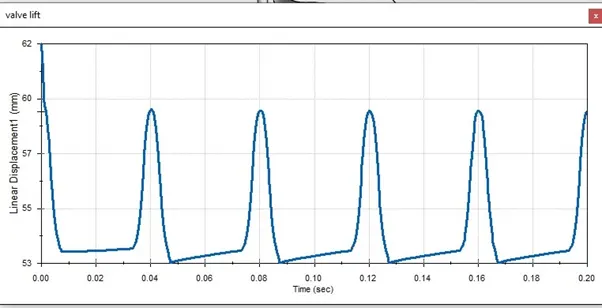
Valve lift
Contact force between cam and push rod
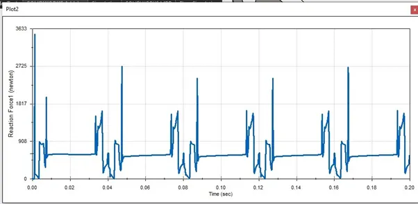
Contact force between push rod and rocker arm
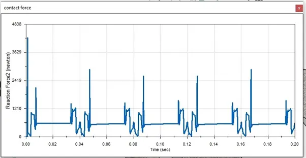
Contact force between rocker arm and valve magnitude
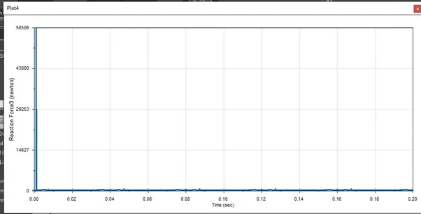
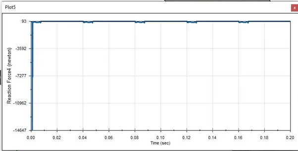
Contact force in x direction between rocker and valve
EXPLANTION
CASE 1
When, CAM LIFT = 3.5mm at rpm =1500
Maximum valve lift comes between 56 to 57 mm according to plot.
The contact force comes between push rod and cam to be 5500 to 7383 N.
The contact force between push rod and rocker arm to be 5924 N.
Then contact force between rocker arm and valve to be between 1223 to 1631 N.
CASE 2
When, CAM LIFT = 6mm at rpm = 1500
Maximum valve lift comes between 62 mm according to plot.
The contact force comes between push rod and cam to be 3833 N.
The contact force between push rod and rocker arm to be 3629 to 4838 N.
Then contact force between rocker arm and valve to be between 58506 N.
TO SEE MOTION ANALYSIS OF THIS VIDEO CLICK OR TAP THAT LINK DOWN BELOW