Planetary Gear
Aim: To study the motion analysis of planetary gear with modelling the sun gear, planet gear, carrier and ring gear using solidworks.
Objective:
- Determination of pitch circle diameter and number of teeths of planet gear
- Determination of pitch circle diameter of sun gear and ring gear based on module and number of teeth given
- Observation of motion analysis of planetary gear and preparing plot of angular velocity of output term as given in problem statement
Theory:
An epicyclic gear train (also known as planetary gear) consists of two gears mounted so that the centre of one gear revolve around the centre of the other. A carrier connects the centres of the two gears and rotate to carry one gear, called planet gear, around the other called sun gear. The planet and sun gears mesh so that their pitch circle roll without slip. A point on the pitch circle of the planet gear traces an epicycloid curve.
Planetary Gear consist of
- Sun Gear
- Planet Gear
- Ring Gear
Problem Statement:
- Ring Gear
- Module = 2.5 (You must use the metric system in design modeller)
- Number of teeth = 46
- Sun Gear
- Number of teeth = 14
- Input Speed of the Gear = 200 rpm.
- Number of planet gears = 4
The dimensions of the carrier depend on the shaft diameter of the planet gear.
With the above input parameters, you are going to run a simulation on the following cases,
|
Sr. No |
Input |
Output |
Fixed |
|
1 |
Sun Gear |
Carrier |
Ring Gear |
|
2 |
Ring Gear |
Carrier |
Sun Gear |
|
3 |
Sun Gear |
Ring Gear |
Carrier |
Calculation:
Calculation to determine the pitch circle diameter and number of teeths of planet gear
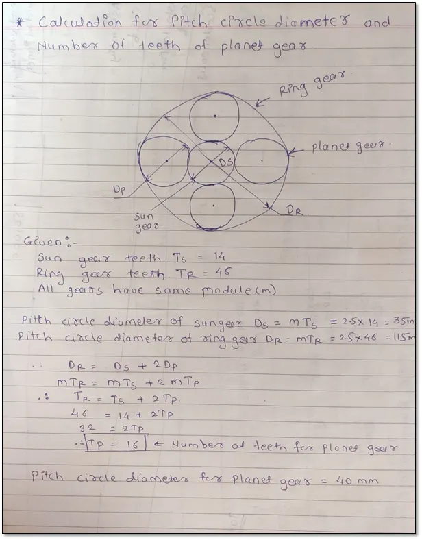
Also we calculate the pitch circle diameter of sun gear and ring gear using module and number of teeths are given.
|
Sr.No. |
Module(mm) |
Gear |
Pitch circle diameter(mm) |
|
1 |
2.5 |
Planet Gear |
40 |
|
2 |
2.5 |
Sun Gear |
35 |
|
3 |
2.5 |
Ring Gear |
115 |
- Modelling
- Sun Gear
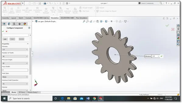
- Planet Gear
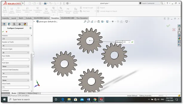
- Ring Gear
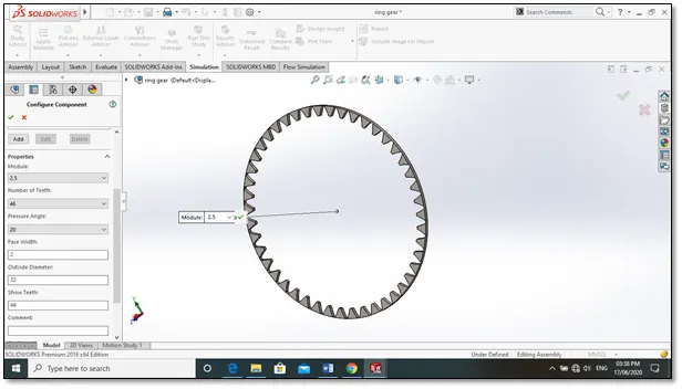
- Carrier
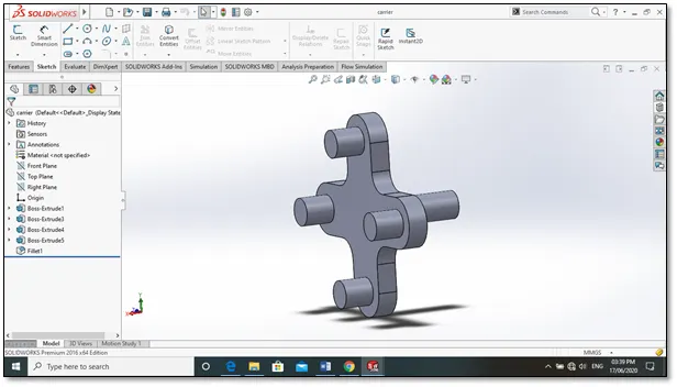
Assembly of planetary gear
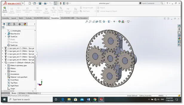
Assembly of planetary gear is given bellow link
https://drive.google.com/file/d/1E2qHqNN_dDw1WSdPI5fiGDmGC8ZFw4cL/view?usp=sharing
- Result
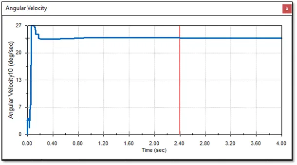
- Case 1:
Input speed of the gear = 200 rpm
Motion to Sun Gear
Ring gear is fixed
Output measure at carrier i.e. Angular Velocity @100 FPS
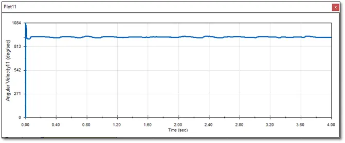
- Case 2:
Input speed of the gear = 200 rpm
Motion to Ring Gear
Sun gear is fixed
Output measure at carrier i.e. Angular Velocity
- Case 3:
Input speed of the gear = 200 rpm
Motion to sun Gear
Carrier is fixed
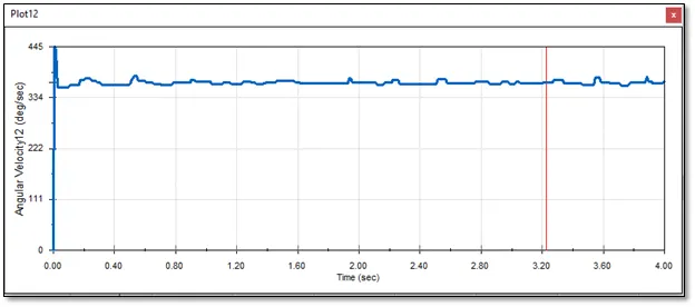
Output measure at ring gear i.e. Angular Velocity
Conclusion
- In case 1 : when the input is given to the sun gear and output is obtained at carrier keeping ring gear fixed then, the planet gear not only rotate about their axis but also forced to roll on the inside of the ring gear since it is fixed. This results in low speed and high torque transmitting capacity.
- In case 2: when the input is given to ring gear and output is obtained from the carrier keeping the sun gear fixed then, angular velocity is maximum since diameter of ring gear is large and planet gears are small so, when large gear meshes with a small gear the velocity is maximum at small gear because velocity ratio is high.
- In case 3: when carrier is fixed and output is obtained at ring gear then, planet gear rotate only about axis and transmit motion from sun gear to ring gear and ring gear is big in diameter the angular velocity achieved is less.
- The deviation in the graph is because of the sliding occur between the gears.
Animation
case 1 :Sun Gear rotated
carrier is output
Ring Gear fix
case 2 :
Input speed of the gear = 200 rpm
Motion to Ring Gear
Sun gear is fixed
Output measure at carrier
case 3 :
Input speed of the gear = 200 rpm
Motion to sun Gear
Carrier is fixed
Output measure at ring gear
Report
1.First all the parts are brought to the assembly file of solidworks.
2.Then emporary axes are enable.
3.The axis of spur gear is made coincident with the right plane.
4.This same procedure is followed for internal gear and carrier.
5.After this, the cylinder of carrier is made concentric with the inside edge of
  the planet gear.
6.After this, the planet gear along with carrier, the sun gear, ring gear are made
  coincident with the right plane of assembly.
7.Then axis of carrier and ring gear is made concentric. Also ring gear is made
  concentric with carrier axis.
8.Then motion analysis takes place using solidworks motion feature.