Flow over an airfoil
Aim: To study the flow simulation over a NACA airfoil at different angle of attack.
Objective:
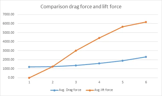
- Calculate the drag force and lift force
- Compare the drag force with varying angle of attack.
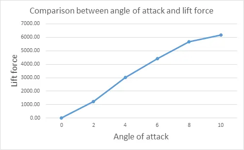
- Compare the lift force with angle of attack.
Theory:
An airfoil is the cross-sectional shape of a wing, blade (of a propeller, rotor, or turbine), or sail (as seen in cross section).
An airfoil-shaped body moving through a fluid produces an aerodynamic force. The component of this force perpendicular to the direction of motion is called lift. The component parallel to the direction of motion is called drag. subsonic flight airfoils have a characteristic shape with a rounded leading edge, followed by a sharp traling edge, often with a symmetric curvature of upper and lower surfaces. Foils of similar function designed with water as the working fluid are called hydrofoils.
The lift on an airfoil is primarily the result of its angle of attack. When oriented at a suitable angle, the airfoil deflects the oncoming air (for fixed-wing aircraft, a downward force), resulting in a force on the airfoil in the direction opposite to the deflection.
The NACA airfoils are airfoil shapes for aircraft wings developed by the National Advisory Committee for Aeronautics(NACA). The shape of the NACA airfoils is described using a series of digits following the word "NACA". The parameters in the numerical code can be entered into equations to precisely generate the cross-section of the airfoil and calculate its properties.
The NACA four-digit wing sections define the profile by:
- First digit describing maximum camber as percentage of the chord.
- Second digit describing the distance of maximum camber from the airfoil leading edge in tenths of the chord.
- Last two digits describing maximum thickness of the airfoil as percent of the chord.
For example, the NACA 2412 airfoil has a maximum camber of 2% located 40% (0.4 chords) from the leading edge with a maximum thickness of 12% of the chord.
The NACA 0015 airfoil is symmetrical, the 00 indicating that it has no camber. The 15 indicates that the airfoil has a 15% thickness to chord length ratio: it is 15% as thick as it is long.
Terminology for airfoil
Problem statement:
- Model the flow over a NACA0017 airfoil
- For the angle of attacks 0,2,4,6,8,10 compare the lift and drag forces
Result:
At zero angle of attack
Velocity distribution
Pressure distribution
At 2 degree angle of attack
Velocity distribution
Pressure distribution
At 4 degree angle of attack
Velocity distribution
Pressure distribution
At 6 degree angle of attack
Velocity distribution
Pressure distribution
At 8 degree angle of attack
Velocity distribution
Pressure distribution
At 10 degree angle of attack
Velocity distribution
Pressure distribution
Drag force and lift force for various angle of attack is given in below table,
|
Angle of attack |
Avg. Drag force |
Avg.lift force |
|
0 |
1186.02 |
0.64 |
|
2 |
1228.70 |
1239.99 |
|
4 |
1347.48 |
3004.36 |
|
6 |
1588.97 |
4403.84 |
|
8 |
1877.04 |
5659.47 |
|
10 |
2299.646 |
6164.235 |
Plot for angle of attack and drag force
Plot for angle of attack and lift force
Plot for drag force and lift force
Conclusion
- Drag force increases slowly with increase in angle of attack and lift force increases rapidly with increase in angle of attack.
- With increase in angle of attack, the velocity of air over airfoil increase.