Plan and Sections
Aim : To draw :
a. Plan
b. Section
c. Dimensioning
Procedure:
Commands used :
a. Dimension - Command "DIMLINEAR" for linear dimension
- To edit dimension style,text etc command "D" .
- To move a dimension line select the grip point and move
- If we place mouse on grip points of extension lines , we can we options such as strech,continue dimension,baseline dimension,flip arrow.
- If we need to move or change the position of text, right click the grip point of text : strech, move with dim line,move text only,move with leader,above dimline,centre vertically,reset text position.
- Command "DIMEDIT" is used to edit the dimension line ,to make it oblique,rotate ,and change it to default.
- For text justification , justification tab is selected from the toolbar in annotate tab.
- Command "DIMBREAK" to break the overalpping dimensions.
-Command "DIMCONTINUE" to continue dimensioning.
Dimension style : Command "D"
- We can create our own dmension style from "new" menu.
- In this all the lines included in dimension ( extension line,dimension line) ,its properties(colour,line weight etc ) can be changed, we can supress extension lines
- In symbols and arrows , we can change shape of arrow head,arrow head sizes,centre marks, break size etc.
- In text, we can set height of text, colour,style.
- In fit option, if there is no space to place text and arrows in extension lines , options can be selected whether either text or arrows or both text or arrows etc., text placement , overall scale adjustments ( all the features of dimension lines ie,arrows ,text etc will chnage to the inputed scale acoordingly).
- Primary units ,we can select the unit format ( decimal , enginerring ,architectural) , precision,decimal separator etc.
- In alternate unit , we can set another unit other than primary unit ,then two units will be displayed , the units positions are all managed here.
- In tolerence, we can set the tolerence level and how it should be displayed in the drawing.
b. Multileader - To mark and and write specification about the particular marked section multileader is used.More than one leader can be used at a time.
- We can create our won style of multileader,.from annotate toolbar ,manage multileade style is selected, then multileader style manager dialogue box appears.
- Select new ,to create a customized one ,or we can change the leader format,structure and content in the modify option.
c. Offset - Command "O"
d. Trim - Command "TR"
e.Line - Command "L"
f. Text - Command "T"
g. Layer- Command "LAYER"
h. Match properties - Command :"MATCHPROP" - to match the properties( colour,line weight etc) of one object to another
Procedure :
a. Plan :
i. Drawing the plan:
* Given outer wall thickness as 250mm and inner wall thickness as 125mm.
* Draw XL -H and XL-V , give the thickness of wall .
* Give the dimension of rooms Bedroom (3100x3100)mm by offset command.
* Give inner wall dimesnion as 125mm by offset method.
* Offset horizontally 2550mm ,125mm, 1250mm(toilet) ,125mm,125mm,1250mm (Toilet of C) ,3000mm ( bedroom of C),250mm (external wall)
* Offset vertically 2400mm ( toilet) and 125mm ,3225mm ( bedrrom ofC) .125mm ( wall thickness).
* Offset vertically 2950mm (drawing/living)from bedroom of C and give wall thickness of 125mm ,3250mm and 3200mm give wall thickness of 250mm.
* Divide the rooms horizontally by offseting 3225mm,125mm,3250mm,125mm,4475mm,250mm.
* Offset 2400mm vertically and 4400mm horizontally for the staircase.
* Offset 3050mm vertically from drawing of C and 3225mm horizontally for the bedroom of B and offset the wall thickness also.
* Offset 3300mmvertically and 3100mm horizontally for thefront bedroom.
* Fillet the wall of the bedrrom with the left side wall and give wall thickness of 250mm.
* Offset 100mm from the outer wall ,Draw verandah by offseting 1000mm and offset 3175mm for the bedroom of A .
* Offset 2888mm for the front bedroom of A and offset wall thickness of 125mm.
* Offset 1225 and 2275 mm for the toilet ,then offset 2550mm for the drwaing/kitchen/dinning of A.
* Fillet all the corners and trim the excess lines.
ii. Creating doors and windows
* For doors and windows following sizes are assumed:
D -1000 x 2100 mm W3 -1500 X 1200 mm
D1- 700 X 2100 mm W2 - 1000 X 1200 mm
D2- 900 X 210mm W1 -900 X 1200 mm
W4- 500 X 500 mm
W- 600 X 1200 mm
* Trim off the size of doors on the walls ,whereever door is required.
* Create windows of given sizes and place it in respective places.
iii. Text
* With multiline text ,command "t"- create text box ,select standard as text style ans text height as 250mm, type the required text.
* Names of rooms with sizes and marking of windows and doors.
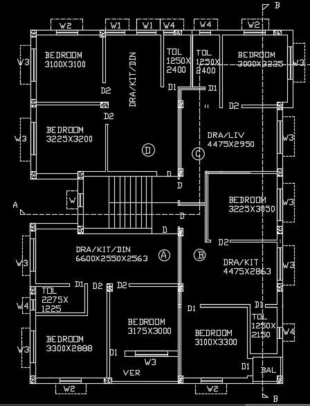
1st,2nd ,3rd floor plan
Scale 1:100
b. Section
i. Section A-A
Assumed dimensions:
-Slab thickness -100mm
- Beam - 300 x350 mm
-Lintel level from florr- 2100mm
- Lintel thickness - 150mm
- Staircase waist slab thickness ,landing slab thickness- 100mm
- Height of newel post -1000mm
* Extend the wall thickness wherever the section cuts the plan.
* Then draw a horizontal line to show the ground level.
* Draw 150mm thickness from the ground level by offseting 150mm from ground level.
* Offset a distance of 2450mm from the ground level for the ground floor height
* Give slab thickness of 100mm from thr top level
* Draw beams wherever the walls are there beam size of 300x350mm.
* Draw columns of 400mm and 300mm width.
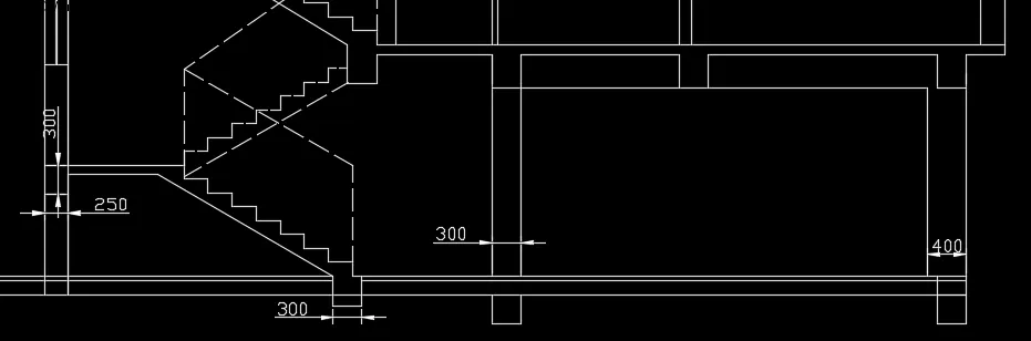
*ii. Drawing stairs:
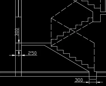
- Draw beam of 300mm width and 270mm depth down the ground level.
- At a distance 1450mm from the 300mm column draw vertical line of 143.75mm ( riser),except the top floor 143.75mm.
- Draw horizontal line of 250mm.(tread)
- Similary draw 8 steps , draw the landing from the 8th one and offset a thickness of 100mm downwards .(1200mm distance from the wall)
- Draw an inclined line joining the riser end of the flight , offset 100mm from that line ( waist slab), then join it with the landing slab.
- Mirror the steps to the opposite side meeting the next floor ,given dotted lines as it won't be visible.
- Draw beam of 300x250mm as landing beam.
- Give the height of newel post as 1000mm on both the start and end of flight,connect it with inclined line.
- 
* For the first floor, offset a height of 2850mm ,also give slab thickness of 100mm and beam of 300x350mm.
* Extend the projected walls of 125mm and 250mm.
* Extend the doors and windows from the plan to get its width , then height is given 1200mm for window and 50mm for ventilator.
* Draw lintel slab of 150mm and projection of shade as 400mm.
* Show section of the window on one end of wall and the stair side as it is cut by the section line.
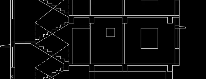
* Similary copy the same in the respective floors , upto 3rd floor
* On top for parapet give height of 1000mm and 2500mm for the top room.
* Draw a door of 900x 2100mm door and wall thickness of 250mm on both sides.
* For overhead water tank, draw a parapet height of 450mm
* Extend the wall thickness and the beam
* For tank, draw a line of 1200mm as height of tank and 2300mm as width of tank.
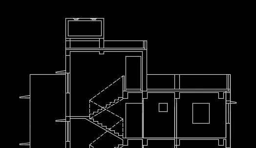
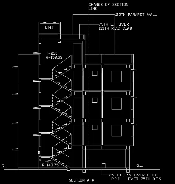
*With the useof multileader text are written.
* Select leader from annottae tab - multileader style manager dialogue box displays.
* Create new - then give the leader points as 5 , text height as 250mm and arrow size as 1000mm.
* Parapet walls are marked.
iii. Text:
* With multiline text ,command "t"- create text box ,select standard as text style ans text height as 250mm, type the required text.
*Tread and riser is mentioned , Overhead water tank is marked.
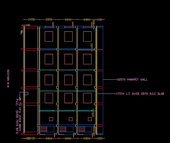
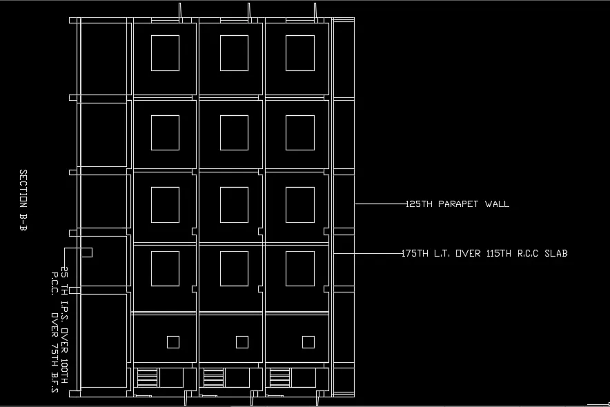
Section B-B
* Project the walls and columns from the plan using line command.
* Mark a vertical line showing Ground level , take offset of 150mm for P.C.C and 200mm from the ground level to show the flooring level.
* Project the windows and ventilators and give the height 2100mm.
* Offset slab of 100mm thickness and draw the beams.
* Show the section of windows wherever the section line cuts the windows
* With multileader , text size -250mm and leader point as 2 , write the text.
c. Dimensioning
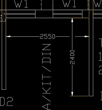
* Command "DIMLINEAR" or from annotate toolbar select dimension-linear.
* Dimension one of the room , then type command "DIMCONTINUE" , then we will be able to select the dimension continously.
* If two dimension intersect each other,select break from the annotate toolbar and select the two dimension, the intersection point will have a break.
* For dimension style , command "D" ,here ISO 25 (default for metric) is selected .
i.Line:
- For dimension line by layer is selected .
- Linetype and line weight are given defualt-Block
- For extension line ,supress extension line is given.
- Extension linetype,lineweight are given default - by block
- Extend beyond dimension line =1.25
- Offset from orgin = 0.625
ii. Symbols and arrows:
- Arrow head and leader - closed filled
- Arrow size -2.5
- Dimension break -3.75
iii. Text:
- Text style - standard
- Text colour - by block
- Text height - 5
- Text alignment- aligned with dimension line
- Text placement -vertical -above
- horizontal- centered
- view direction - left to right
iv. Fit:
- If there is no space to place text and arrows in extension lines , whether either text or arrows or both text or arrows is selected.
- Test placement - beside dimension line
- Overall scale-50.
v. Primary units:
- Decimal is selected
- Precision 0.0 is selected
- Decimal seperator -period
vi. Altrenate units and tolerence are not given here.
* If two dimension overlap we can use command "DIMBREAK" then overlapping will be eliminated.
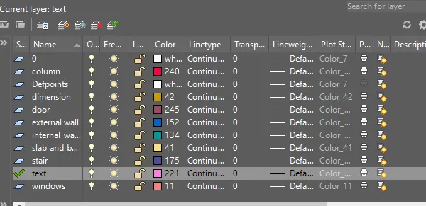
* Each component are placed in layers -9 layers are created.
* Layers for external wall, internal wall, windows, doors, text, dimension, stairs,column, slab and beam
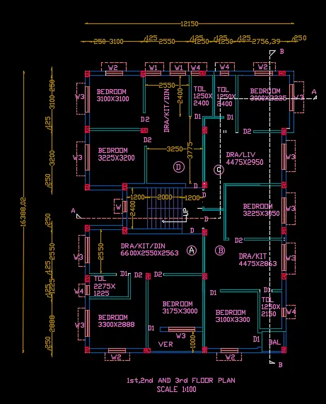
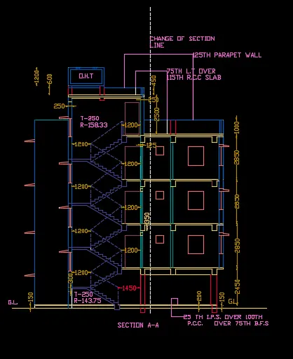
RESULT: Following shows the plan ,section and dimension done using dimension techniques .
i. Plan
ii. Section A-A
ii. Section B-B