Auto Cad Project -2 : Drawing of footing , house plan layout by coordinate methods and steps and gable wall by isometric method
C1. Cross section of load bearing wall over spread footing
Aim : To draw cross section of wall over footing.
Procedure:
Step:1 - Create rectangle by typing "REC"in command box
- Specify the first corner point ( the point where it should start)
- Click on dimension in the command box
- Specify the length of rectangle =0.9 units in command box
- Specify width of rectangle =0.25 units in command box

Step:2- Create another rectangle -"REc" in command box.
- Specify the first corner point - specify the point which is 0.2 units(with dynamic input on) from the starting point of first rectangle.
- Click on dimension in command box
- Specify the length of rectangle as 0.5 units
- Specify the width of rectangle as 0.4 units.
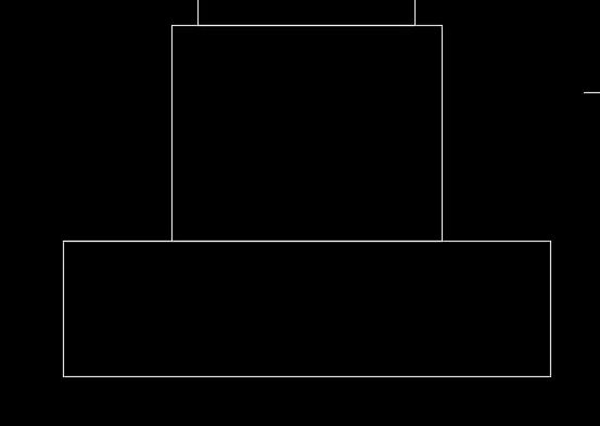
Step:3 - Create the third rectangle command- "REC"
- Specify the first corner point 0.05 units from the corner of the second rectangle.
- click on dimension in command box
- Specify the length of rectangle as 0.4 units
- Specify the width of rectangle as 0.4 units.
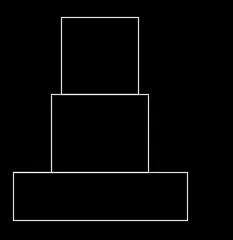
Step :4 - Line is drawn from the corner of third rectangle, command "L"
- Give the length as 1.15 units
- Move cursor downwards and give value 0.15 units
-Move cursir to right and give length as 1.15 units.
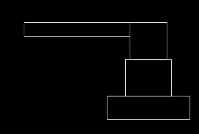
Step:5 - Fourth rectangle is drawn ,command -"REC"
- Specify the first cornerpoint at a distance of 0.05 from the third rectangle
- Click on dimension
- Give the length as 0.3
- Give the width as 0.6
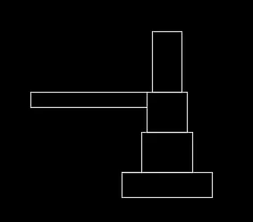
Step:6 - from the line drawn in step 4, at a distance of 0.3 ,draw another line.
- "L" - give the distance of 0.15 units vertically and 0.3 units horizontally.
- Continue it two more times ,until 3 steps are created.
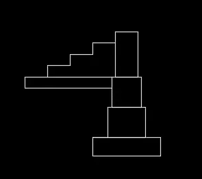
Step:7 -Draw another rectangle above fourth rectangle,command -"REC".
- Specify the corner point as the corner of the fourth rectangle
- Click on dimension -give length as 0.3 units and width as 0.05 units
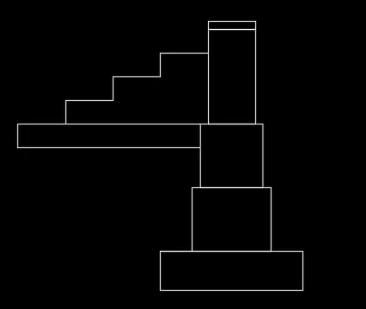
Step:8 - Drawn the fifth rectangle command -"REC"
- Specify the corner point as the corner of fourth rectanglr
- Click on dimension -give length as 0.3 units and with as 1 unit.
- Erase the unwanted line by "trim"(between rectangle 2 and 3).
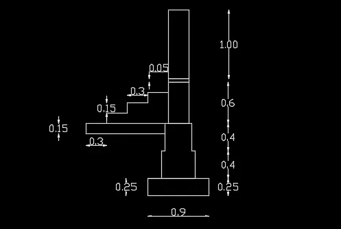
RESULT: The footing is drawn as shown:
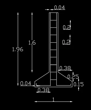
C.2 C/s of a isolated footing
Aim - To draw c/s of a isolated footing.
Procedure:
Step1: - Draw line with command "l" and give 1 units.
- give command "l" and give the relative coordinates as @ 0,0.15
- Give the next coordinate as @ 0.38,0.25.
- Next coordinate is given as @0,1.6
- Give @ 0.24,0
- Next coordinate @0,-1.6
-Next coordinate @0.38,-0.25
- Next @ 0,-0.15 or close.
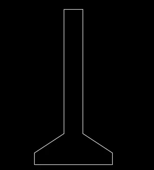
Step:2 - draw line at a distance of 0.04 units from the top command"l"
- With dynamic input on give value 0.04 ,then give the length of 1st line as 1.96
- Next give the coordinate @0,-0.38 for the 2nd line
- Draw the third line,bend by giving the coordinates @0,0.06
Step 3: -Copy the first line by command "co" - click displacement and give value of 0.16 units.
- Copy the second 2nd line horizontal by "co" click on the base point and draging to desired position.
- Cop the 3rd line by giving command "co" and selecting the base point of the object.
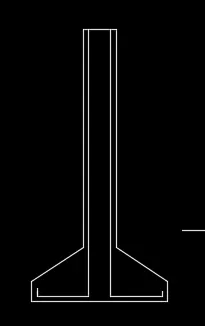
Step:4 - Give offset from the top line with an offset distance of 0.2 units.
- Give the command"o" an select the object-give the offset distance as 0.2 -select multiple option an 9 such lines
- Trim the excess lines
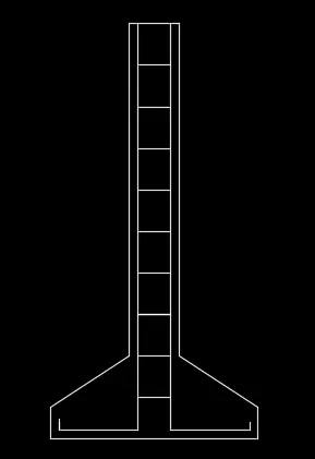
RESULT: C/S of isolated footing is shown:
C3 .Line diagram of a two bedroom building
Aim : To draw line diagram of 2 bedroom building
Procedure:
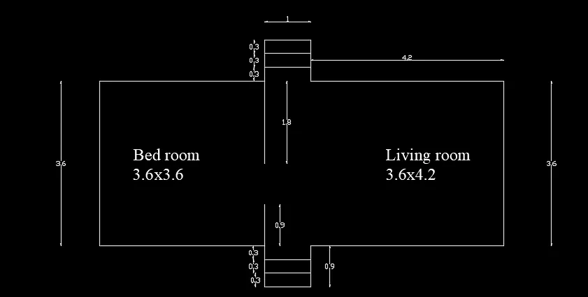
Step :1 - Creating bedroom room (3.6x3.6)by polyline .
- Command "PL" - click a point and move the cursor downwards (-y axis)and give 0.9 units
- As it gives contionus lines,move the curosr to left (-x axis)and give 3.6 units
- Move cursor to top(+yaxis) and give distance as 3.6 units and then cursor to right (+x axis)and give 3.6 units
- Position the cursor to down (- yaxis) and give 1.8 units
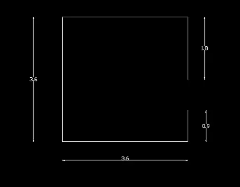
Step:2 -The step outline is created using line tool
- from the corner point of 1.8 units ,line is drawn
- command "l" - line is drawn at adistance of 0.9 unit vertically.
- Then cursor is moved to + x direction and a distance of 1 unit is given
- again 0.9 unit is given moving the cursor to - y direction.
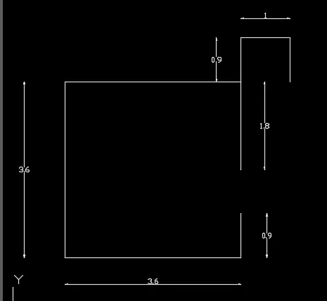
Step:3 The living room is drawn by polyline
- Command "pl" - from the last point start the polyline
- Give 4.2 unit in positive x direction.
- Move the cursor to-y direction and give 3.6 units
- Move the cursor to- x direction and give 3.6 units
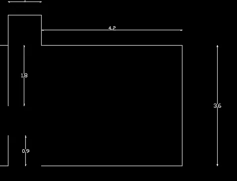
Step :4 - Create outline of step with line as in step 2
- Command "l" -select the last point drawn
- Move the cursor to - y direction draw 0.9 units
- Moving cursor to - x direction draw 1 unit
- Moving cursor to + y direction draw 0.9 units.
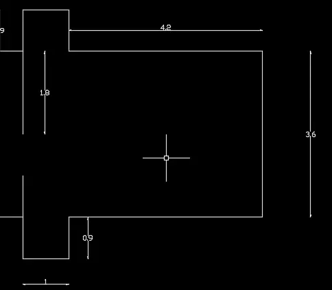
Step : 5 Creating step usng offset
- Command "o" - give offset distance as 0.3 unit -select the object
- Click on multiple and move the cursor to the direction where it is to be drawn.
- Reapeat the same on the other side also.
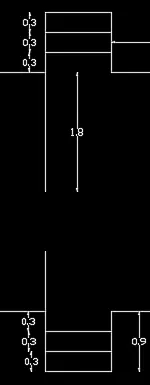
RESULT:
The line sketch of 2 bedroom is drawn:
C4 . Cross section of a load bearing wall showing foundation details
Aim : To darw the c/s of load bearing wall showing foundation details.
Procedure:
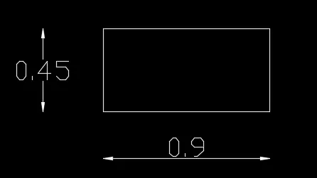
Step:1 - Create a rectanglecommand"REC"
- Specify the starting point
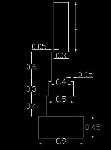
-Click on dimesion and give the length as 0.9 units and width as 0.45 units.
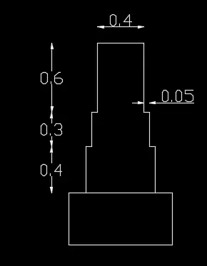
Step:2 - By polyline create rest
- Comand "PL" ,with dynaic input on specify the first point 0.15 unt from the corner of rectangle
- With cursor pointing + y direction ,give the distance as 0.4 units.
- With cursor pointing towards + x direction ,give the distance as 0.05 units.
- With cursor pointing towards + y direction ,give the distance as 0.3 units.
- With cursor pointing towards + x direction ,give the distance as 0.05 units.
- With cursor pointing towards + y direction ,give the distance as 0.6 units.
- With cursor pointing towards + x direction ,give the distance as 0.4 units.
- With cursor pointing towards - y direction ,give the distance as 0.6 units.
- With cursor pointing towards + x direction ,give the distance as 0.05 units.
- With cursor pointing towards - y direction ,give the distance as 0.3 units.
- With cursor pointing towards + x direction ,give the distance as 0.05 units.
- With cursor pointing towards - y direction ,give the distance as 0.4 units.
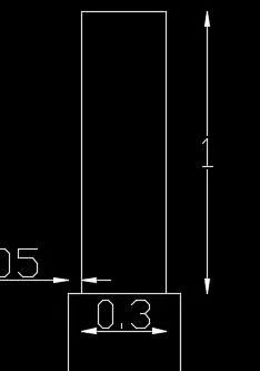
Step:3 - The top portion is drawn by polyline
- Command "PL" select the first point by dynmaic input on at a distance of 0.05 from the last drawn.
- With the cursor pointing towards + y direction, drawn 1 units
- With cursor pointing towrads +x direction ,draw 0.3 units
- With the cursor pointing towards - y direction, drawn 1 units
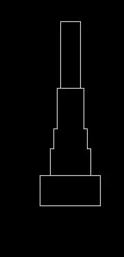
RESULT: The c/s of loadberaing wall foundation details is shown:
C .5 Isometric view of steps
Aim : To draw the isometric view of steps
Procedure:
- To work with isometric view -command "ds" - snap off ,grid off .put isometric snap on
- Make sure that ortho mode is on
Step :1 - From isometric drafting select isoplane left.
- give command "l" and moving the cursor to -x direction(left) give 1 units
- Moving the cursor to+ y direction (top) ,give 0.15 units.
- Moving the cursor to + x direction angain give 1 unit and cursor to -y direction(downwards) give 0.15 unit.
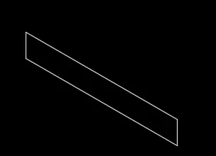
Step:2 - Change the isometric drafting to isoplane top
- Move the cursor to back and give 0.3 units from the last drawn point.
- Move the cursor to right direction and guve 1 unit
- Move the cursor to front and give 0.3 unit
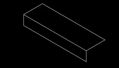
Step:3 - change the isometric drafting to isoplane right
- Copy the object drawn ,ortho off -
- Command "co" and specify the base point and place it to new point
- Repeat it until 4 steps are formed

Step :4 Copy the horizontal distance of 0.3 downwards on the starting end of step with isoplane right
- Also copy the vertical distance of 0.15 on the last end of step .
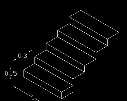
Step:5 - With isoplane right join the two ends with ortho off
- line Command "l" ,select first point as the bottom point drawn in step 4 and the second point as end point of vertical line drawn in step 4.
Result: The steps are drawn in isometric view.
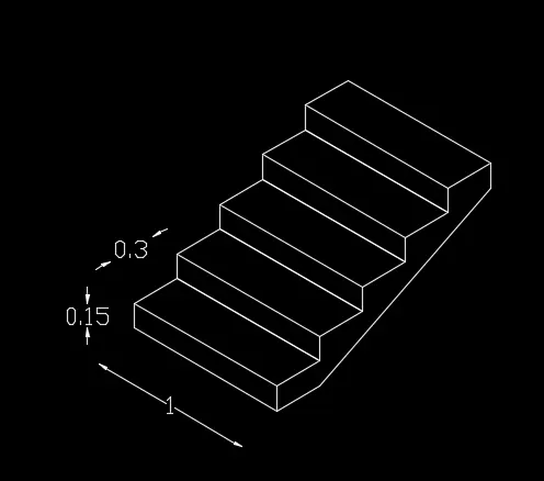
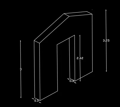
C.6 Isometric view of gable wall
Aim : To draw the isometric view of gable wall
Procedure:
- To work with isometric view -command "ds" - snap off ,grid off .put isometric snap on
- Make sure that ortho mode is on
Step:1 - From isometric drafting select isoplane right.
- Give command "l" and moving the cursor to left give 1 units
- Pointing the cursor upwards give 3 units
- Draw 3 units to right and 3 units downwards.
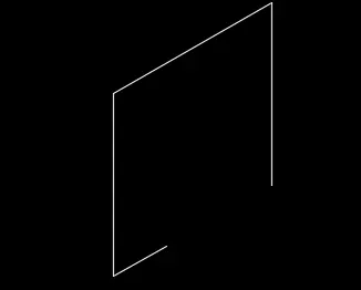
Step:2 - In isoplane right
- Again take line command and draw line upwards of 2.42 units from the starting point of step 1
- Draw 1 unit towards the right and 2.42 units downwards
- Click on the end point of figure in step 1 ,so that a closed figure is obtained.

Step 3 - Change to isoplane left and draw0.3 units as thickness on the left side of figure.
- Move the cursor upwards and draw 3 units and join

Step :4 - Give the thickness of opening ,isoplane left
- 0.3 units towards left and 2.12 unit upwards.
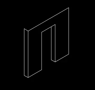
Step:5 - Extend the thickness line of opening 1.13 units upwards ie, total 3.25 units from bottom
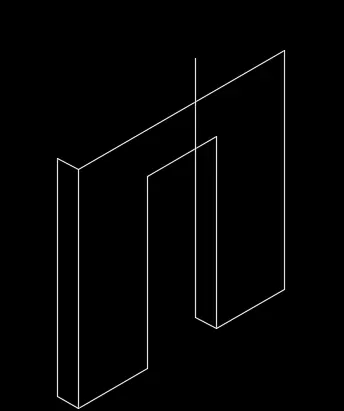
Step :6 - With ortho off, draw a line between the corner of left side and the projected line done in step 5
- Draw it to the other side also till it meets the right corner.
\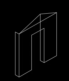
Step:7 - Draw the vertical line with ortho on to join the centre portion and earse the projected and horizontal lines
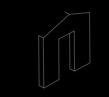
Step 8 : Copy both the inclined lines and join the right end.
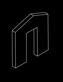
Result: The isometric view of gable wall is drawn: