Pipe Flow Simulation with varying inlet Reynold's number
Aim :
Run a pipe flow simulation with an inlet Reynolds number of 100,1000 and 10,000.
For each of these cases do the following
- Place line probes at 95%, 90% and 85% of the pipe length.
- Compare the normalized velocity profile at each of these locations
- Normalize the velocity profile by the inlet velocity.
Modelling :
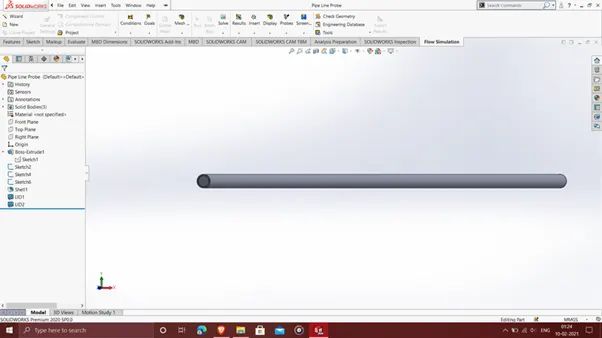
The diameter and length of the pipe is 10mm and 1000mm respectively, with line probes at 850mm, 900mm and 950mm from the inlet of the pipe. The wall thickness is at 1mm.
The pipe is shown below,
Results :
Reynold's Number = (Velocity at inlet * Diameter of the Pipe)/ Kinematic Viscosity
Fluid Assumed is water.
Kinematic Viscosity of water = 1.787 m^2/s
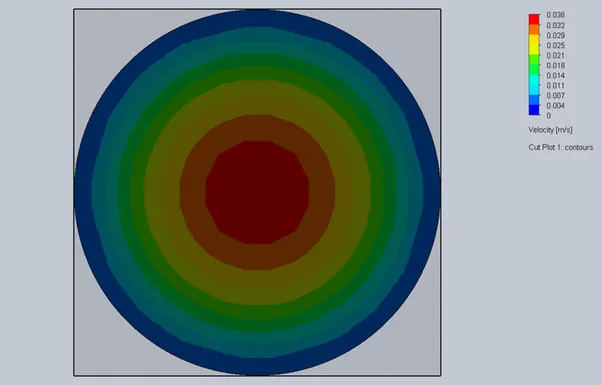
Case 1 : Reynold's Number = 100
Inlet Velocity = 0.01787m/s
Cut Plot :
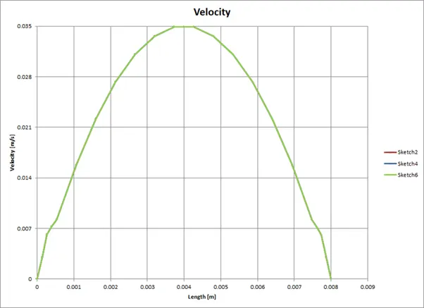
Comparitive Velocity Profile :
Sketch 2 is line Probe at 95%
Sketch 4 is line probe at 90%
Sketch 6 is line probe at 85%
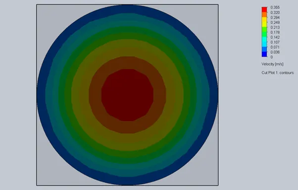
Case 2 : Reynold's Number = 1000
inlet velocity = 0.1787m/s
Cut Plot :
Comparitive Velocity Profile :
Sketch 2 is line Probe at 95%
Sketch 4 is line probe at 90%
Sketch 6 is line probe at 85%

Case 3 : Reynold's Number = 10000
Inlet velocity = 1.787m/s
Cut Plot :
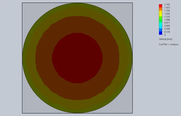
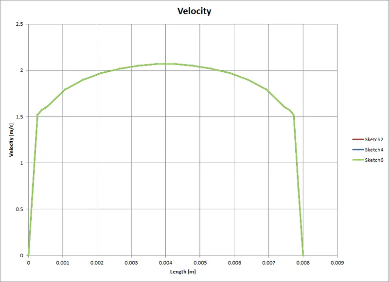
Comparitive Velocity Profile :
Sketch 2 is line Probe at 95%
Sketch 4 is line probe at 90%
Sketch 6 is line probe at 85%
Normalized Velocity Plot :
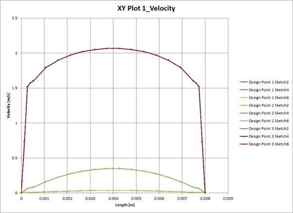
Conclusion :
As the Reynold's Number was increased, the Flow gradually transitioned from a laminar flow to a turbulent flow