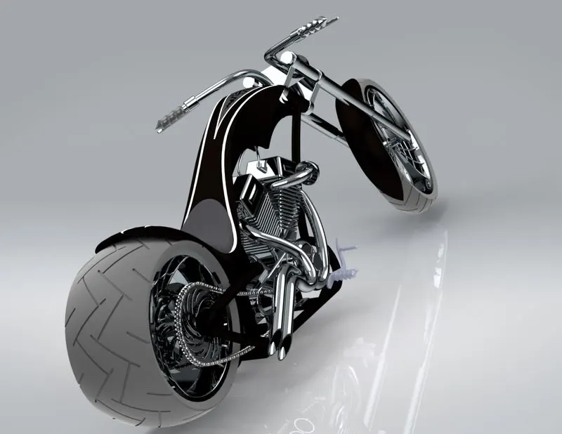
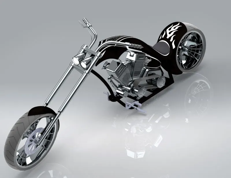
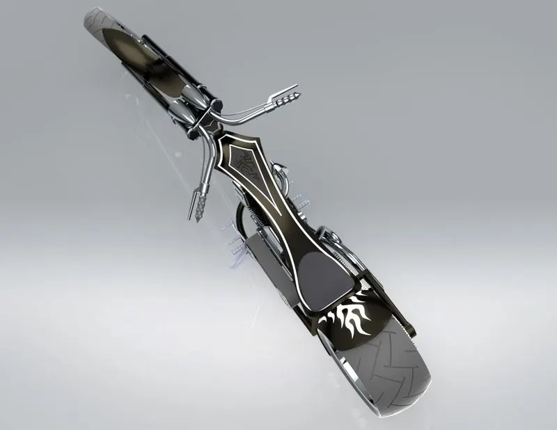
Photo Realistic Rendering
TITLE: Design of american chopper by using solidworks
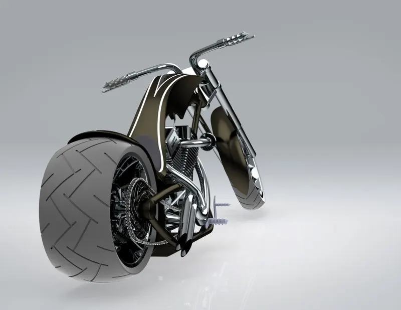
Objective:The obsective of the project is to design the american chopper from scratch .By modeling each component of the chopper in solidworks and to make professional renderings of the chopper in solidworks visualize.
Introduction:
Solidworks is a Computer Aid Design software where 3D solid modeling ,Assembling and analysing the components can be done easily.
In this design of American chopper in solidworks,let us see how the features and tools of the solidworks are usefull to model and assemble the chopper
Design Methodology:
1.Creating an idea (MOOD Board)
2.Converting idea to sketch
3.Assuming the dimensions of the sketch .
4.Converting the sketch of each part to a solid model.
5.Assembly of each solid component.
6.Making the parts to look more releastic as possible by using solidwork visual
DESCRIPTION:
Initially all the parts of the chopper are sketched and then they are converted to solid by using the solidworks features
Parts of the American_chopper are
1.Transmission belt
2.Kick stand
3.Front Fender
4.Rear Fender
5.Chain
6.Oil tank
7.Pedal
8.Front Wheel
9.Rear Wheel
10.Front fork
11.Chasis
12.Engine
13.Gas tank
Above parts are modeled by using the solidworks features,let us see the modelling of each part and features used
Basic sketch tools used are:
line,3 point arc ,spline ,rectangle,circle,etc.
Basic features used are:
extrude boss,loft ,dome,extrude cut,split,fillet,Revolve,curvepattern,mirror, combine,shell,split,chamfer,revovlve cut,projection of curves,sweep,composite curve,surface sweep,surface loft,boundary surface ,sweep cut.
1.Transmission belt:
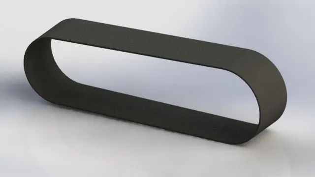
The modeling of the Transmission belt is done by using the extrude boss feature
extrude boss:It is useful to create a solid 3D models.It extrudes a sketch or selected sketch contours in one or two directions to create solid feature and we can add material to the feature.
2.stand:
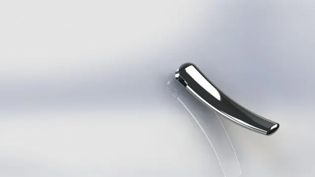
Features used are
Loft:It is a feature which helps mainly to add materials between two profiles with ease,the profile should be closed
extrude cut:
It is a feature which helps to remove materials from the 3D model
Split:It is a feature which helps to remove the unwanted solid parts when we are dealing with the multiple bodies at a time
Fillets:It is a feature which is used to rounding of the interior or external face along with one or more edges
The filleting is used to reduce the stress concentraction effect
3.Front Fender& Rare Fender
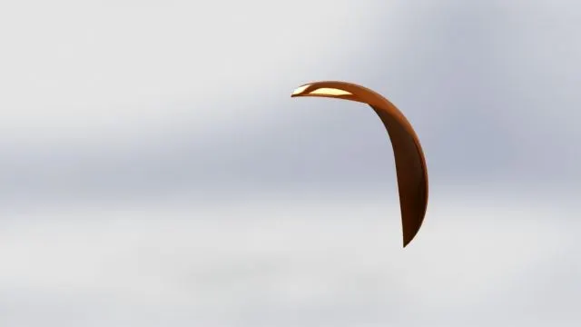
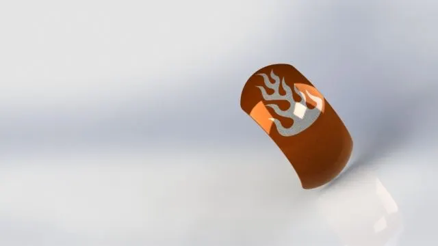
Revolve:Revolve boss is used to create solid 3D model around an axis.It can revolve the sketch on axis to add materials to it
4.chain:
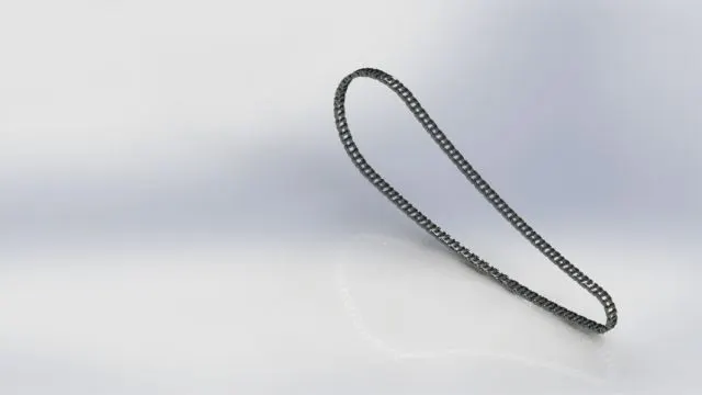
linear pattern,circular pattern :It is a tool allows to create patterns along a planer or a 3D curve to define the pattern you can use any sketch segment or the edge of a face that lies along the plane .
Mirror:Mirroring is another way that solid works can create a copy of an existing object
5.Oil tank:
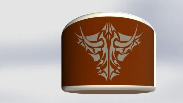
Combine:It is used to create a single solid body by using multiple bodies
shell:It is used to create an hellow inside the solid body
6.Pedal:
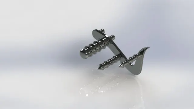
Chamfer:It helps to cut or make edges or corner of 3D model in straight
for rounding purpose we use fillet tool
7.Front wheel,Rear Wheel:
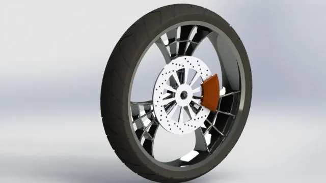
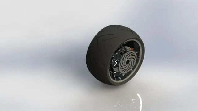
Revolve cut:It is used to remove the material from 3D models by revolving a closed profile
along an axis
8.Front Fork:
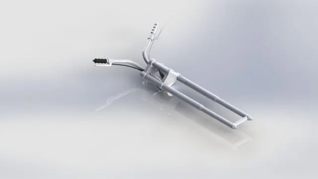
Projection of curves:It is used to create a 3D curve that represents the intersection of two extruded surfaces generated by creating sketches on two intersecting planes
sweep:
It helps to sweep a closed profile along a closed or open path
ENGINE:
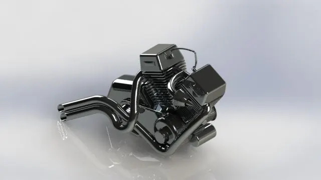
Composite cuves:It is used to combine two curves
Gas tank:
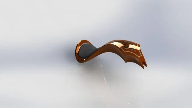
Extrude surface:It is provided to extrude a closed or an open sketch to create an extrude surface
surface Knit:It is used to Knit the surfaces to gether to create a single surface
sweepcut:creates a sweep cut by moving a 2D profile along a 2D or 3D sketch path
Boundary surface:The boundary surface feature lets you create surfaces that can be tangent or curvature continuous in both directions.
The part design of the chopper has been done
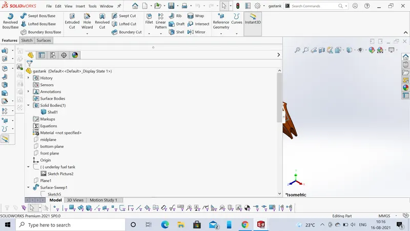
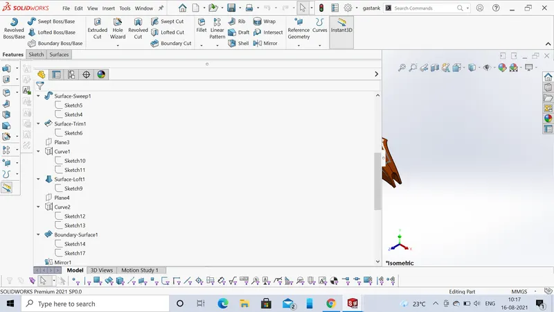
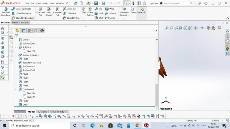
In the above part design the feature tree of part tells us the features that are used to complete the part.
example of feature of a gas tank
ASSEMBLY:
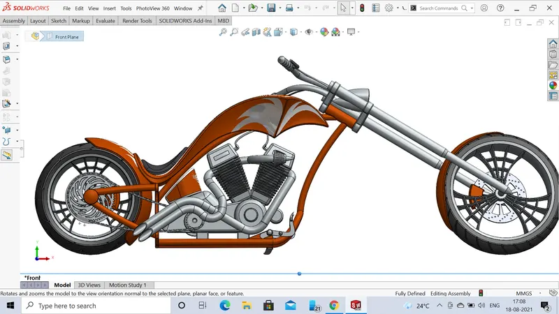
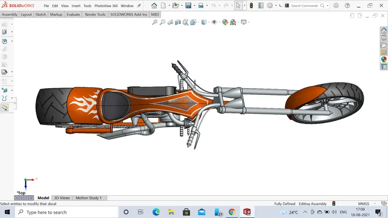
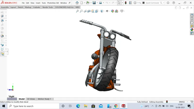
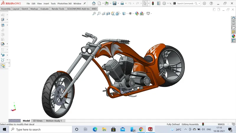
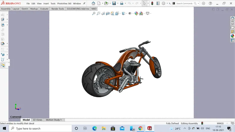
mates that are used in the assembly of chopper are
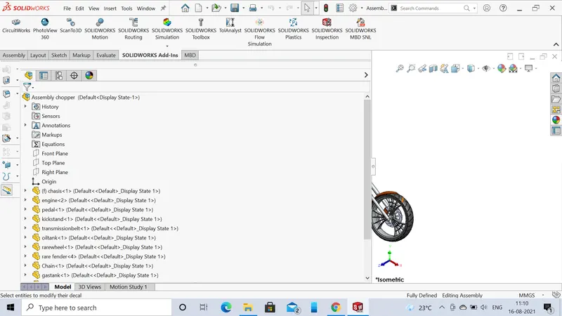
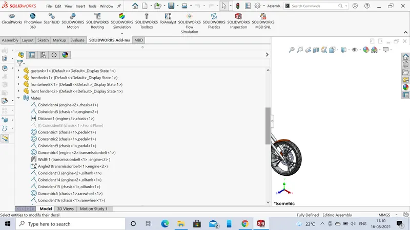
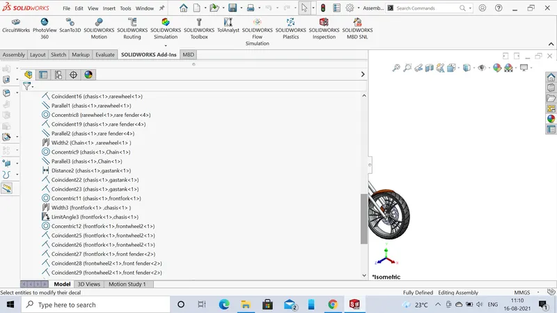
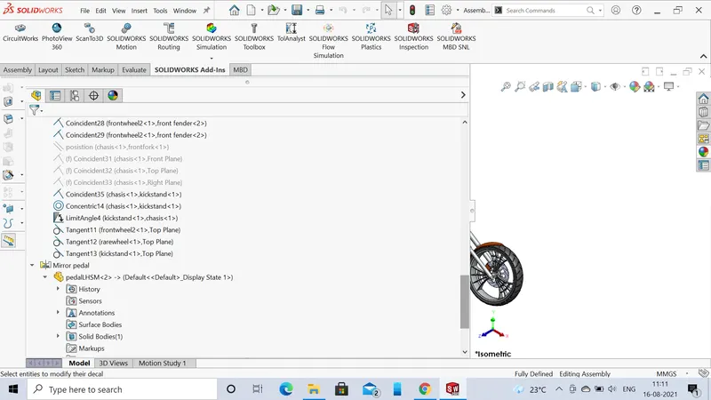
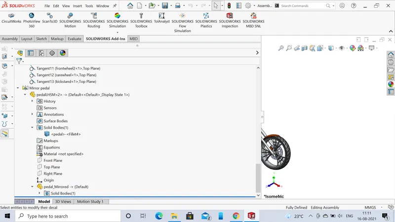
1.All theparts that are designed are assembled in solidworks .The solid works provide a flexiblity that when a part is been mate in assembly.if their dimensions are to be changed we can easily navigate to the part in assembly or it can be changed their it self which helps in update of the part.
2.Addition of materials can be done easily to the assembly parts.
RENDERING THE ASSEMBLY:
The rendering of the assembly to make the design to look as realistic as possible.This is done by using photo360 and solidworks visual.
1.In solidworks visual the assembly file is imported.In this we can add or remove material and we can add scenes for the background.
2.Decals are applied to the parts where they are required
3.The rendered images of the chopper are