Fender Design - Wheel Arch Challenge
AIM :
THE calculate the Wheel Arc area and prove whether the car will pass the standards or Not.
Fender :
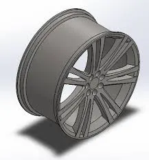
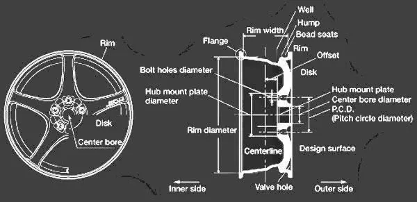
Fender wheel arch regulations :
- The Clearance ‘L’ should be measured at sections SA-SA, SB-SB, SC-SC, SD-SD and SE-SE and create clearance check chart to validate
- At all the five sections the value of L should be greater than 10mm to satisfy the European Regulations
- Wheel guard requirement: The value of ‘a’ should be more than 5mm at line 30° forward and 50° rearwards from the central vertical axis of the wheel
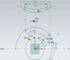
- The clearance ‘L’ for tire, hub, cap and fender is to be measured within area K and create clearance check chart to validate
- The value of L should be greater than 5mm at all positions
- Wheel guard requirement: The value of ‘a’ should be more than 5mm at line 30° forward and 50° rearwards from the central vertical axis of the wheel
US Standards :
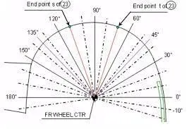
- Clearance ‘L’ is to be checked at all positions from -100° to 100° and create clearance check chart to validate
- The value of L should be greater than 5mm to satisfy the regulations
- Wheel guard requirement: The value of ‘a’ should be more than 5mm at line 30° forward and 50° rearwards from the central vertical axis of the wheel
Calculation of wheel arch area according to European standards :
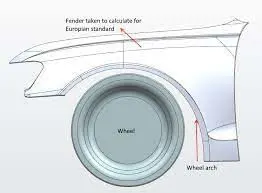
For calculation of clearance between Wheel Arch and Wheel we have to create a sketch on the outer most face of the wheel. The procedure of which is given below.
- A Datum Plane is created at the outermost face of the wheel
- The sketch is created on the new Datum Plane
- A Horizontal line is drawn across the centre of the wheel
- A perpendicular line SA is dropped at the centre of the wheel
- Two lines SB and SC are created at 30° forward of SA and 50° rearward of SA respectively
- A point is created 150mm vertically above the centre line
- A line SE is drawn from the wheel centre and passes from the point created
- Another line SD is drawn from the centre of the wheel and in the middle of lines SC and SE
Obtaining the clearance L at the designated 5 points:
The clearance distance 'L' is calculated at points SA-SA, SB-SB, SC-SC, SD-SD and SE-SE, which should be greater than or equal to 10mm
i.) Clearance 'L' at SA-SA
L = 14.952mm (Pass)
ii.) Clearance 'L' at SB-SB
L = 15.00mm (Pass)
iii.) Clearance 'L' at SC-SC
L = 5.18mm (Fail )
iv.) Clearance 'L' at SD-SD
L = 2.551mm (Fail)
v.) Clearance 'L' at SE-SE
L = 3.357mm (Fail)
Measuring the clearance vlaue'a' for Wheel Guard Requirement:
i.) Clearance 'a' at 30° line SB
a = 45.636 mm
ii.) Clearance 'a' at 50° line SC
a= 38.462mm
For calculation of clearance between Wheel Arch and Wheel we have to create a sketch on the outer most face of the wheel. The procedure of which is given below.
- A Datum Plane is created at the outermost face of the wheel
- The sketch is created on the new Datum Plane
- A Horizontal line is drawn across the centre of the wheel
- A perpendicular line SA is dropped at the centre of the wheel
- Two lines SB and SC are created at 30° forward of SA and 50° rearward of SA respectively
- A point is created 150mm vertically above the centre line
- A line SE is drawn from the wheel centre and passes from the point created
- Another line SD is drawn from the centre of the wheel and in the middle of lines SC and SE
Obtaining the clearance L at the designated 5 points:
The clearance distance 'L' is calculated at points SA-SA, SB-SB, SC-SC, SD-SD and SE-SE, which should be greater than or equal to 10mm
i.) Clearance 'L' at SA-SA
L = 14.952mm (Pass)
ii.) Clearance 'L' at SB-SB
L = 15.00mm (Pass)
iii.) Clearance 'L' at SC-SC
L = 5.18mm (Fail)
iv.) Clearance 'L' at SD-SD
L = 2.551mm (Fail)
v.) Clearance 'L' at SE-SE
L = 3.357mm (Fail)
Measuring the clearance vlaue'a' for Wheel Guard Requirement:
i.) Clearance 'a' at 30° line SB
a = 45.636 mm
ii.) Clearance 'a' at 50° line SC
a= 38.462mm
CONCLUSION:
the above results we can conclude that the Fender does not pass the European Regulations, as the minimum clearance L between the Fennder Wheel Arch and Wheel for vehicle and pedestrian safety is 10mm and this design does not meet all the requirement.