Modelling and Rendering of American Chopper
Objective
To model the American chopper with specific dimensions and constraints and rendering of final assembly in photo view 360 or Solidworks visualize.
Introduction
In this project, I had to model the American chopper according to the dimensions given. After completion of the modelling of individual components then do an assembly following any one of the assembly approaches from the top down or bottom up. After the creation of a successful assembly, I had to import the assembly into the rendering environment. But before that, I had to set up the camera and light environment to give the perfect realistic look in the render.
Design Methodology
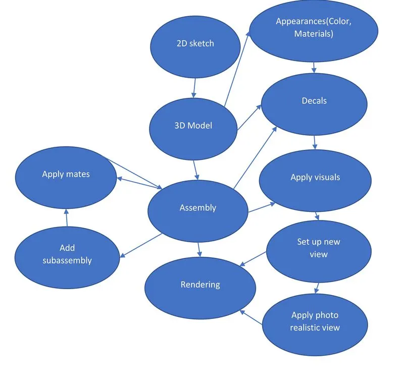
Description
All components used in this project were designed using the above-mentioned design methodology.
The following command was used in designing the components:
- Sketch Commands:
- 2D sketch, 3D sketch, mirror, sketch fillet, line, circle, rectangle, spline, trim, extend, smart dimensions, sketch picture, convert entities, arc, slot, sketch pattern
- Features:
- Boss Extrude, Extrude cut, lofted boss/base, Revolve boss/base, fillet, chamfer, dome, shell, sweep boss/base, pattern(curve driven), mirror
- Additional Commands:
- Projected curve, Composite curve, Reference plane, Sketch Blocks
All components were designed with the help of the above-mentioned commands but not all commands were used in designing all components.
The following components were used in American Chopper:
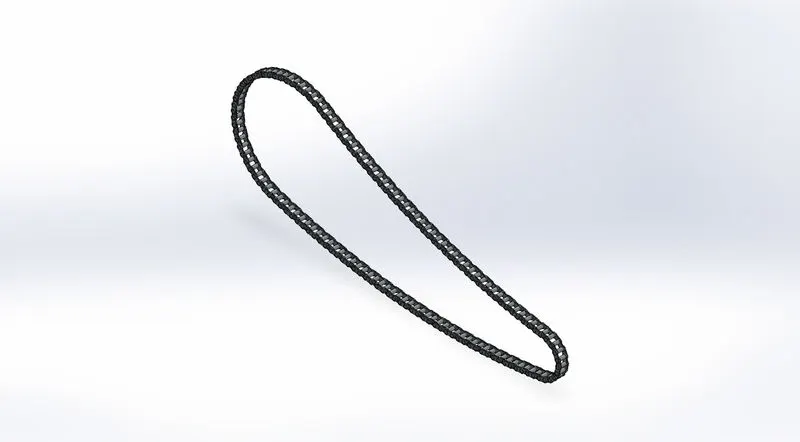
- Chain
The chain is used for connecting the engine to the rear wheel.
It is used to transfer the rotor/motor power from the engine to the rear wheel to generate the rotary motion to move the vehicle forward.
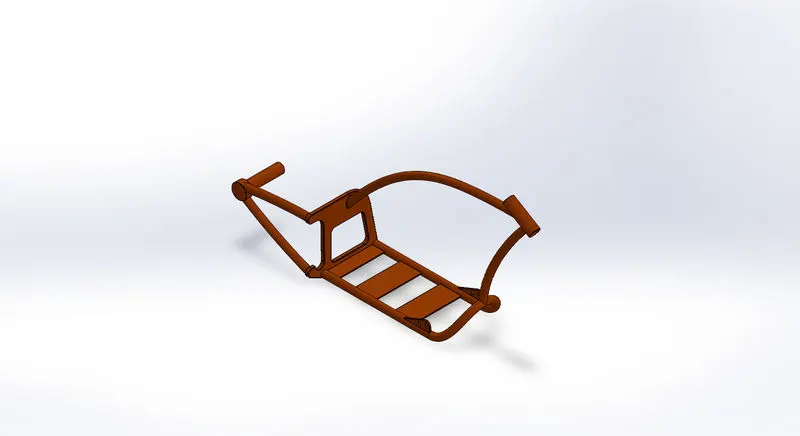
- Chassis
It is used to support all the components of the vehicle and is also known as the main body or the mainframe.
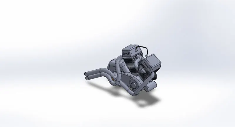
- Engine
Also known as the powerhouse of the vehicle. It has various other internal components such as pistons, cylinders, gearbox, valves, etc. Commonly the engine used in 2-wheelers is a 2-stroke engine but now a days 4-stroke engine is also used. The exhaust is also connected to the engine.
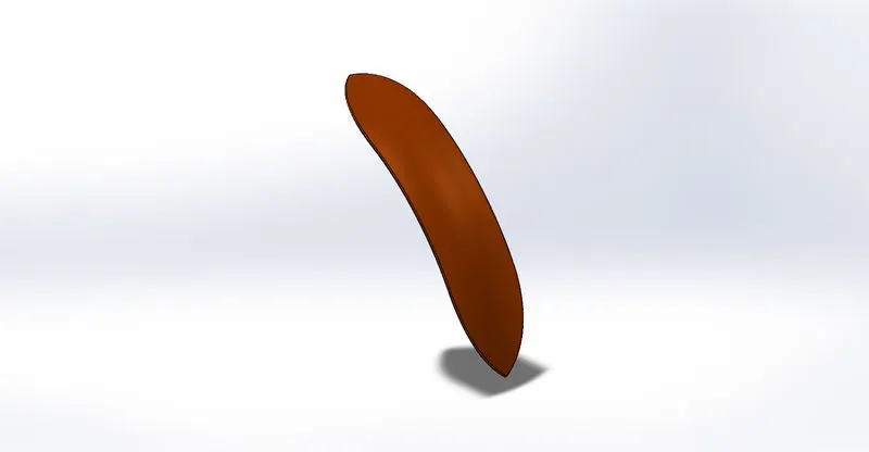
- Front fender
The main function of this component is to protect the driver from the water splash while driving the bike in rain or muddy or on rough terrains.
- Front fork
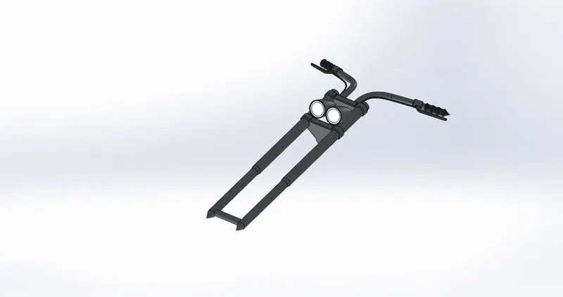
This component is the combination of different small components together.
The two handles of the front fork are connected by the yokes.
It is also an important component of the motorcycle as it helps to steer the motorcycle, so the stability of this component is most important.
It includes an axle which is used to connect the front wheel, then dampers or also known as shock absorbers, which provide stability to the vehicle by absorbing the shock and vibration and preventing it from transmitting further to the driver.
The next part is the handle of the motorcycle which is used to guide the motorcycle during curves and also acts as a steering mechanism.
The headlights are also placed on the fork.
Other smaller components such as the horn, turn signal buttons, ignition switch, brake handles, and the speedometer are placed on the handle.
Front turn signals lights are also placed on the fork.
The motorcycle that has a windshield is also placed on the fork, above the headlights using it as the base.
- Front-wheel
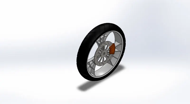
The function of this component is to help steer the motorcycle and also absorb the shock.
It also provides mounting for different components such as brakes, and suspensions.
They are also made to cope with radial and axial forces.
- Oil Tank
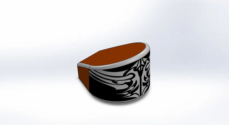
This component is as the name suggests, used to store the oil which is used during the combustion process which takes place in the engine to generate power. (used in case of the chopper)
Generally, the purpose of this tank is to store oil and lubricate all the components which have bearings and the chain of the motorcycle. Also, if the brakes use a hydraulic braking system then the oil is used from this tank as well.
- Gas tank
As the name suggests, it is used to store fuel (petrol), which is used during the combustion process in the engine to generate power.
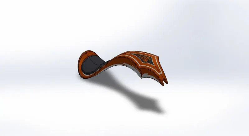
In this model, I have made the seat and gas tank combined.
The gas tank is located above the engine, as it provides the cover and protects it from direct contact with rainwater and snow.
- Kickstand
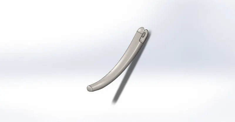
This part of the motorcycle is used to support the weight of the motorcycle when we have parked the vehicle.
It is used to prevent the bike from leaning against anything or another person.
When the bike is in motion it is kept in a horizontal position and brought down when we park it.
It is generally located at the centre of the motorcycle.
- Pedal
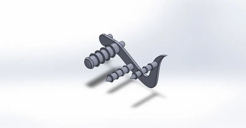
The pedal can be used to rest the foot while riding the bike. Although it is not the main function of the pedal.
The pedal on the right-hand side of the bike contains a brake, but we should avoid it using at all costs and use it only in case of emergency.
The pedal on the left-hand side contains the gear shift levers, which are connected to the gearbox, and used in the transmission to increase or reduce the speed of the motorcycle.
- Rear fender
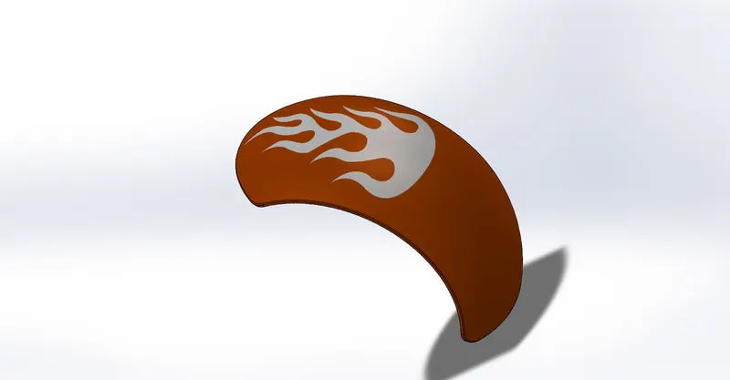
The rear fender also acts in the same way as the front fender.
It is located on the rear wheel and connected to the chassis by nuts and bolts or by joints (welding)
In some bikes, the rear tail signals are located on the rear fender so that they are noticed easily by the person who is far away behind.
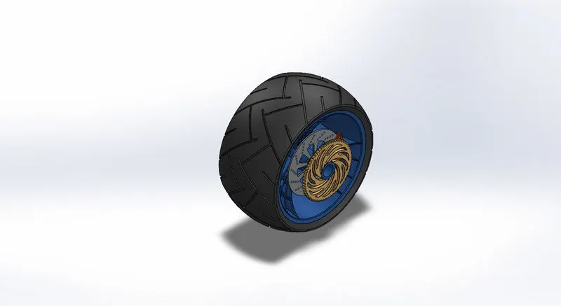
- Rear wheel
The rear wheel is attached to the engine or precisely gearbox or transmission unit with chain.
The main function is to propel the vehicle forward.
The rear shock absorbers are connected from the chassis to the front of the rear wheel.
It also contains the rear braking system along with the rear calliper.
If the vehicle is using a belt as a transmission type then the sprocket (represented by golden color) is replaced by a shaft.
- Transmission belt
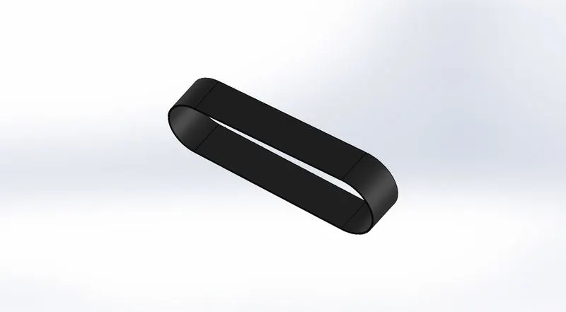
The transmission belt is used to transmit the power. It transmits the power from the driver pulley to other driven pullies.
Modern-day bikes use the chain as a transfer way to transmit the power from the engine to the rear wheel.
When the transmission belt is used as a medium to transmit power from the engine, then the sprocket on the rear wheel is replaced with a shaft.
Assembly
When all the components are modelled then we proceed with the next step, which is combining the parts in the order to generate a meaningful output.
There are 2 types of assembly approaches followed in Solidworks namely the top-down approach and the bottom-up approach.
I use a bottom-up approach, I find it feasible and easy to use.
In this approach, we import the parts which we have already created.
The main disadvantage of this approach is that we cannot make any major changes to individual components in the assembly, for that we have to edit the part and then the changes will be done in assembly accordingly.
It is the traditional assembly approach.
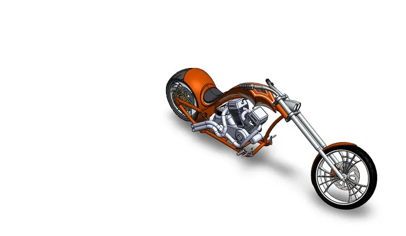
Figure: Chopper Isometric view
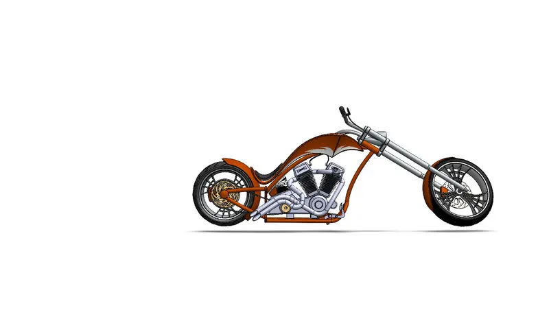
Figure: Chopper Side View
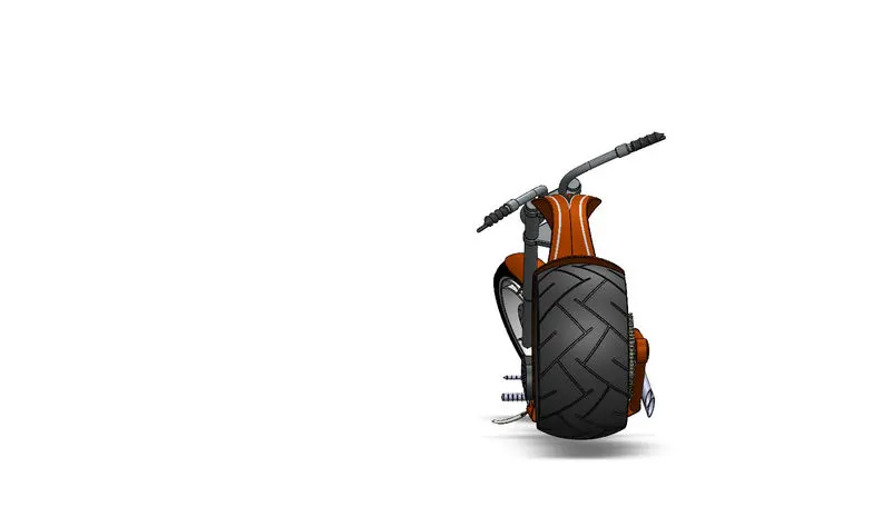
Figure: Chopper Back view
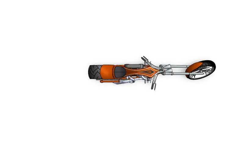
Figure: Chopper top view
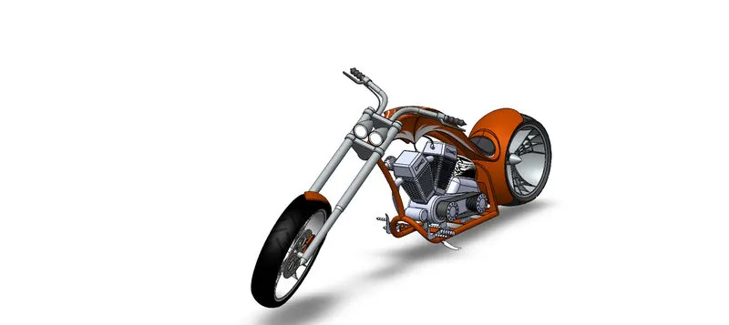
Figure: Chopper camera set-up view
Rendering
Rendering means the generation of the photorealistic image using software.
We can use the plugin called photo view 360 or Solidworks Visualize which is a standalone product of Solidworks and have high rendering capabilities.
We can check how our model, product, and design will look in actual or real life after it has been manufactured.
We can set up our custom camera angle, and adjust the focal length, height and many more parameters. It also allows us to set up a new light environment, where we can use directional light, adjust the lights applied in the model or even adjust the sunlight.
When we create a new environment, we can adjust the texture, use lighting, edit the decals, apply new scenes, and adjust shadows.
After we are satisfied with the scene and background environment we can run render. There are types of render. Preview – it is the setup shot and will not run a background pass. Fast render – it has 2 modes, speed or quality. It will also give accurate results but it uses faster raytracing speed. Accurate render – it used normal raytracing speed and usually takes because it uses exact light paths. Powerboost – it requires an external visualize boost machine.
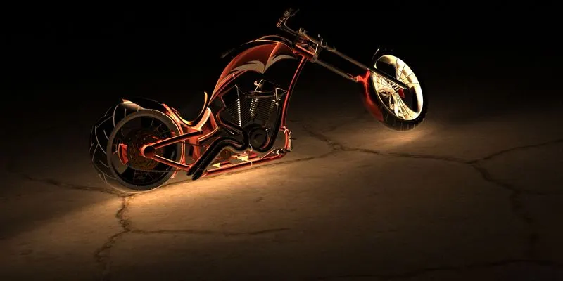
Figure – render type: fast, hdr background, focus on shadow
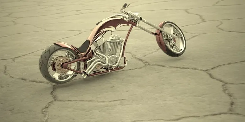
Figure – render type: fast, with hdr background
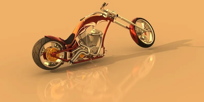
Figure – accurate render without any hdr background, light studio
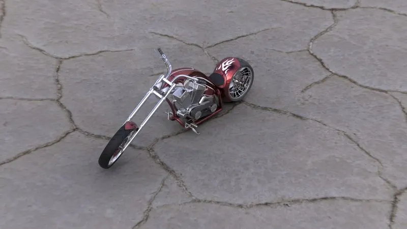
Figure – render type: sun study
Conclusion
This project helps me:
- To understand the importance of the fully defined sketch
- Rendering of models