Photo Realistic Rendering
Modelling of an American Chopper
using SolidWorks
BE (Mechanical Engineering)
by
Prajat Uday Sawant
Contents
Title
Introduction
Objective
Design methodology/approach
Descriptions
Rendering images
Conclusion
Introduction
For any kind of design, we first design CAD model using a software to get a solid body model this method is called solid body modelling, where the designer can visualize the overall final view of the component. 3D modelling makes it easier to identify the problems in modeling and can easily make the changes to meet its requirements.
This project focuses on creation 3D model of American Chopper using Dassault SolidWorks 3D modelling software. A Chopper is a type of custom motorcycle which emerged in the US state of California in the late 1950s. A chopper employs radically modified steering angles and lengthened forks for the stretched-out appearance. They can be built from an original motorcycle which is modified (“chopped”) or built from scratch. Some of the characteristics features of choppers are long front ends with extended forks often coupled with and increased rake angle, hardtail frames (frames without rear suspension), very tall “ape hanger” or very short “drag” handlebars, lengthened or stretched frames, and larger than stocks front wheels. The “sissy bar”, asset of tubes that connect the rear fender with the frame, and which are often extended several feet high, is a signature feature on many choppers.
Objective
The aim is to learn concepts that are employed to design American Chopper using Dassault SolidWorks 3D modelling software. Drawing sketches in 2D and making it in 3D using the various features; applying the appearance to parts; applying decals; assembling the parts using mates to get the model of American Chopper. Also rendering the full chopper images to look realistic by adding lightings, camera setups, backgrounds.
Description
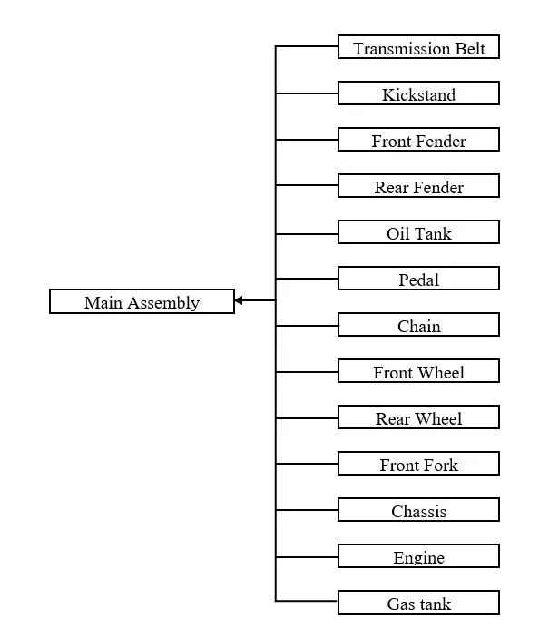
Features and Tools used for designing Surface Modelling of an Aston Martin Car
Features
- Boss/Base
Extrude Boss/Base - Extrudes a sketch or selected contours in one or directions to create a solid feature.
Revolve Boss/Base - Revolves a sketch or selected sketch contours around an axis to create a solid feature.
Sweep Boss/Base - Sweeps a closed profile along an open and closed path to create a solid feature.
Loft Boss/Base - Adds material between two or more profiles to create a solid feature.
- Cut
Extrude Cut - Cuts a solid model by extruding a sketched profile in one or two directions.
Revolve Cut - Cuts a solid model by revolving a sketched profile around an axis.
Sweep Cut - Cuts a solid model by sweeping a closed profile along an open or closed path.
- Features
Fillet/Round - Creates a rounded internal or external face along one or more edges in solid or surface feature.
Chamfer - Creates a bevel feature along an edge, a chain of tangent edge or vertex.
Shell - Removes material from a solid body to create a thin-walled feature.
Dome - Adds one or more domes to selected planar or non-planar faces.
Combine - Combines two or more solid bodies.
Split - Creates multiple bodies from a single body.
Move/Copy  - Moves copies and rotates solid and surface bodies.
Delete/Keep Body - Deletes or keeps one or more solid or solid bodies.
- Patterns/Mirror
Linear Pattern - Patterns features, faces and bodies in one or two linear directions.
Circular Pattern - Patterns features, faces and bodies around an axis.
Mirror - Mirrors features, faces and bodies about a face or a plane.
Curve Driven Pattern - Pattern features, faces and bodies based on a curve.
- Surface
Surface Extrude - Creates an extruded surface.
Surface Sweep  - Creates a surface feature by sweeping an open or closed profile along an open or closed path.
Surface Loft  - Creates a lofted surface between two or more profiles.
Boundary Surface  - Creates a boundary Surface between profiles in two directions.
Surface Trim - Trims a surface where one surface intersects with another surface, a plane or a sketch.
Knit surface - Combines two or more adjacent, non-intersecting surfaces together.
- Curve
Split Line - Projects a sketch to curved or planar faces, creating multiple separate faces.
Projected Curve - Projects a sketched curve onto a face or sketch.
Composite Curve - Combines selected edges, curves and sketch into a single curve.
- Reference Geometry
Plane - Adds a reference plane.
Axis  - Adds a reference axis.
Tools
- Sketch Entities (Line, Conner Rectangle, Centre Rectangle, Parallelogram, Straight Slot, CenterPoint Straight Slot, Polygon, Circle, Tangent Arc, 3 Point Arc, Ellipse, Spline, Point, Centerline, Midpoint Line)- Creates a various 2D standard sketches.
- Sketch tools
Fillet - Pounds the corner at the intersections of two sketches or two lines.
Offset Entities - Adds sketch entities by offsetting faces edges, curves or a sketch entity.
Trim Entities - Trims or extends a sketch entity to be coincidence to another or deletes a sketch entity.
Extend Entities - Extends sketch entity to meet another sketch entity.
Mirror Entities - Mirrors selected entities about a centerline or planar reference.
Linear Patterns - Adds a linear pattern of sketch entities.
Circular Pattern - adds a circular pattern of sketch entities.
- Dimensions
Smart Dimension - Creates a dimension for one or more selected entities.
- Relations
Add Relations - Controls the size or position of entities with relations such as concentric, vertical, etc.
Display/Delete - Displays and deletes geometric relations.
Rendering images
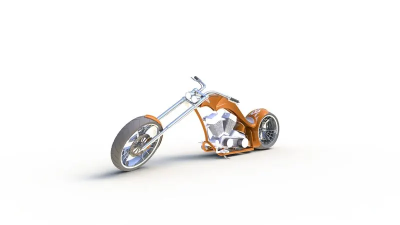
Camera Setup View
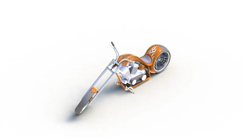
Isometric View
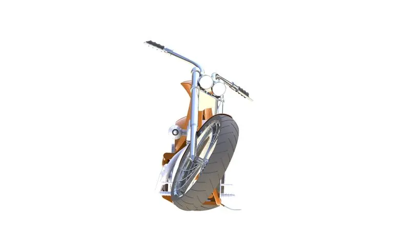
Front View
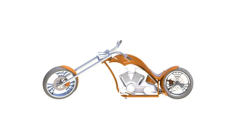
Side View
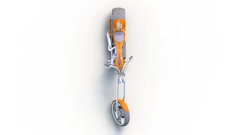
Top View
Conclusion
The various features and tools for 2D and 3D along with modelling concepts in SolidWorks were successfully implemented by replicating the American Chopper. Along with the rendering the images, adding lights camera setups etc., of the final assembly of the Chopper to realistic images.