Flow over an airfoil
Flow Over an Airfoil Simulation
using SolidWorks
BE (Mechanical Engineering)
by
Prajat Uday Sawant
Contents
Title
Introduction
Objective
Case Setup
Observations
Conclusion
Introduction
Airflow over the aerofoil is the prime factor in aerodynamics. Flow pattern has tremendous effect on aerodynamic reaction on aerofoil. There are patterns of airflow, airflow terminology, effect of pattern of flow and importance of streaming objects.
The airflow over an airfoil produces forces over the airfoil surface, that is, lift, drag and thrust forces. The airflow velocity is lower on the “pressure” side of the airfoil and accelerates, resulting in lower average pressure, on the “suction” side of the airfoil.
The airfoils are structures with specific geometric shapes that are used to generate mechanical forces due to relative motion of the airfoil and surrounding fluid. The shape of the airfoil greatly influences the aerodynamic performance.
Lift Force: defined perpendicularly to the direction of the oncoming airflow. It is a consequence of the unequal pressure on the upper (suction) and lower (pressure) airfoil surfaces.
Drag Force: defined parallel to the direction of the incoming airflow. This force due to viscous friction forces at the airfoil surface and to unequal pressure on the airfoil surfaces facing toward and away from the incoming flow.
Flow pattern over an object especially the aerodynamically designed objects (e.g., wings of an aeroplane) has very important effect. Aerodynamic reaction for producing desired lift forces with minimum unwanted drag forces is the prime objective of the aerodynamically shaping the wings and the other aerodynamic surfaces. Properly shaped objects that ensure flow over it is laminar/streamlined is called streamlined object and the stream line flow over such objects (e.g., wings) has the contribution towards producing lift, while the cross flow creating turbulence destroys lift and produces more drag which is evil for most of the part of the flight.
Objective
The aim is to understand and simulate the transient flow over an Airfoil in SolidWorks by increasing the angle of attack by 0°,2°,4°,6°,8°&10° and observe the variation of velocity & pressure in a domain. Also finding the Drag and Lift force and plotting it with Angle of Attack.
Case setup
At the beginning of the simulation the part/model is required to be made. NACA0017 airfoil model is created in SolidWorks using tools and features giving a proper angle of attack as shown in figure Fig.1, then part/model (cylinder) is saved. The angle of attack has been changed by using rotate entities tool about the origin.
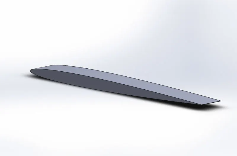
Fig.1
Firstly, for zero angle of attack simulation has been made by creating a new simulation giving the name of the project. For this project it has chosen the analysis type as external, and physical features as Time-dependent (transient analysis). Under Time-dependent setting Total analysis time as 5 seconds and Output time step 1 seconds. The fluid is being taken as Air. Then the desired flow direction is being added, in this case the flow direction is add flow x-axis as shown in figure Fig.2. The velocity is taken as 600m/s.
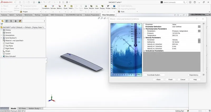
Fig.2
A computational domain is created. In computational domain the fluid enters the domain, flow over a cylinder and will exit the domain in positive direction. Changed the computational domain by edit definition and selected a 2D simulation, selected XY and adjust the domain size at inflow and outflow sufficiently, i.e.; 10m along positive x-axis and 4m along negative x-axis, also 6m along both positive and negative y-axis as show in Fig.3.
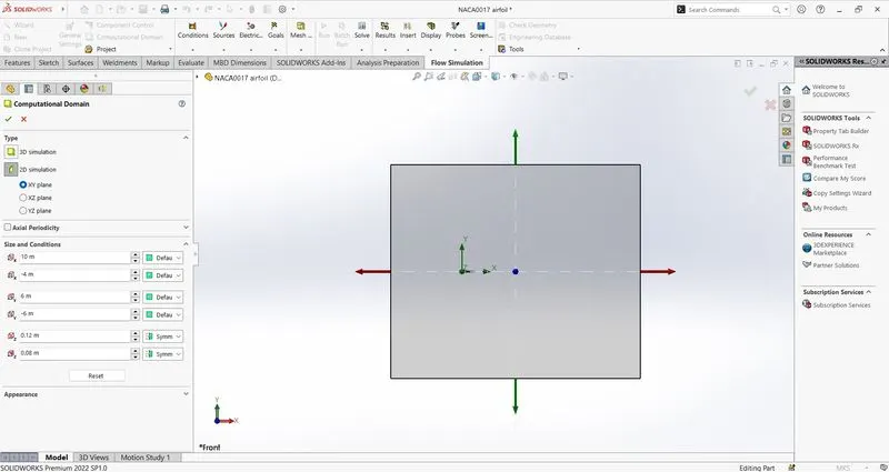
Fig.3
Inserted desired list goals to be obtain while doing the calculations. In this case goals are add as surface goals which is force along x-direction and y-direction. After adding the goals, the local mesh is been added to refine the mesh at the surface of the airfoil. Run the simulation. Observed the goal plots if it converging to a certain value. After reaching the converging value stopped the calculations and saved the results. as shown in Fig.4.
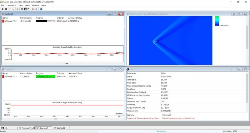
Fig.4
Inserted the cut plots of velocity and pressure and loaded the results. observed the plots and exported the values of goals to excel sheets. Followed the same steps for rest of the change in angle of attack.
Observations
Velocity Contours:
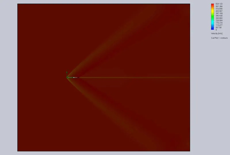
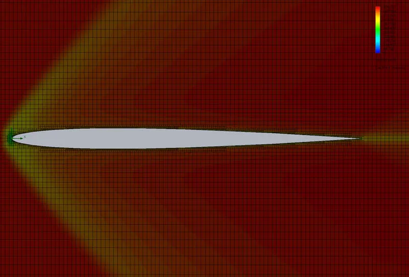
- For 0° angle of attack
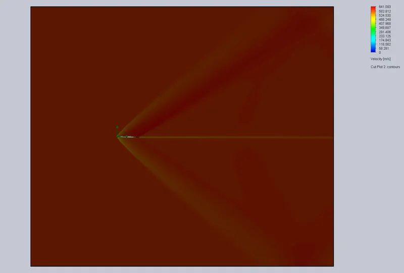
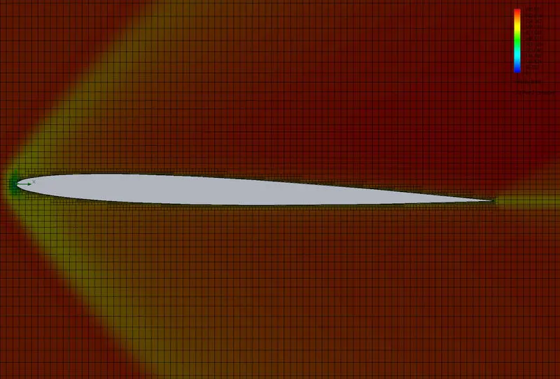
- For 2° angle of attack
- For 4° angle of attack
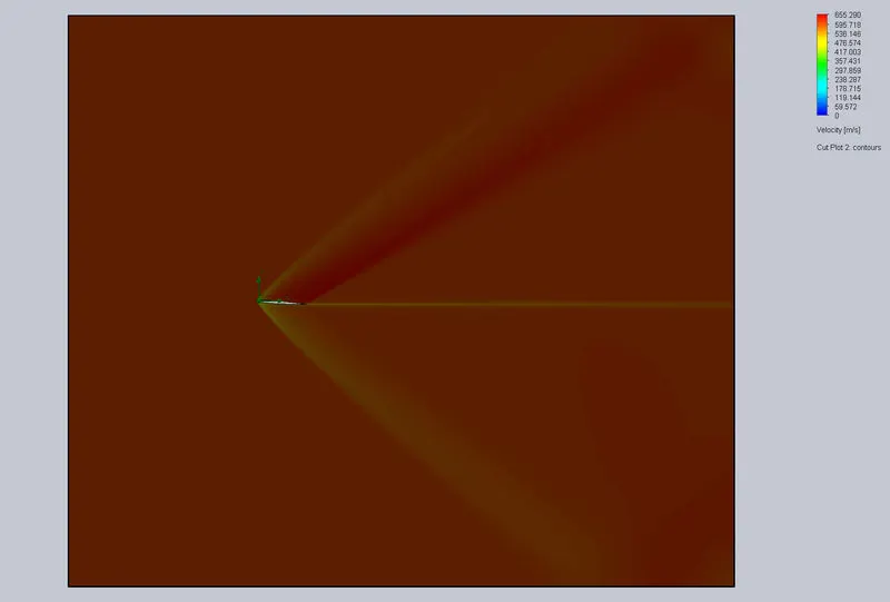
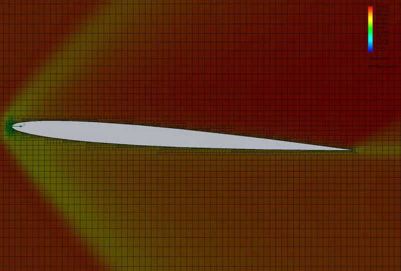
- For 6° angle of attack
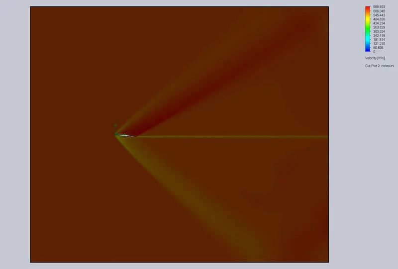
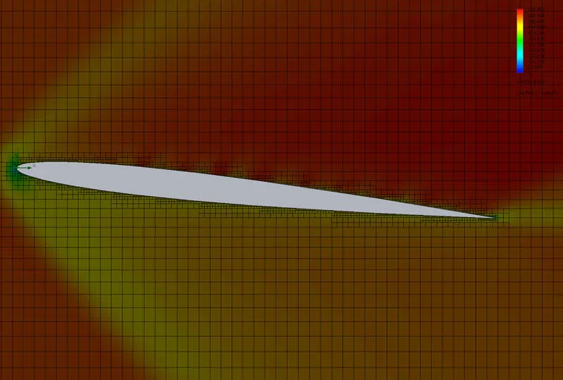
- For 8° angle of attack
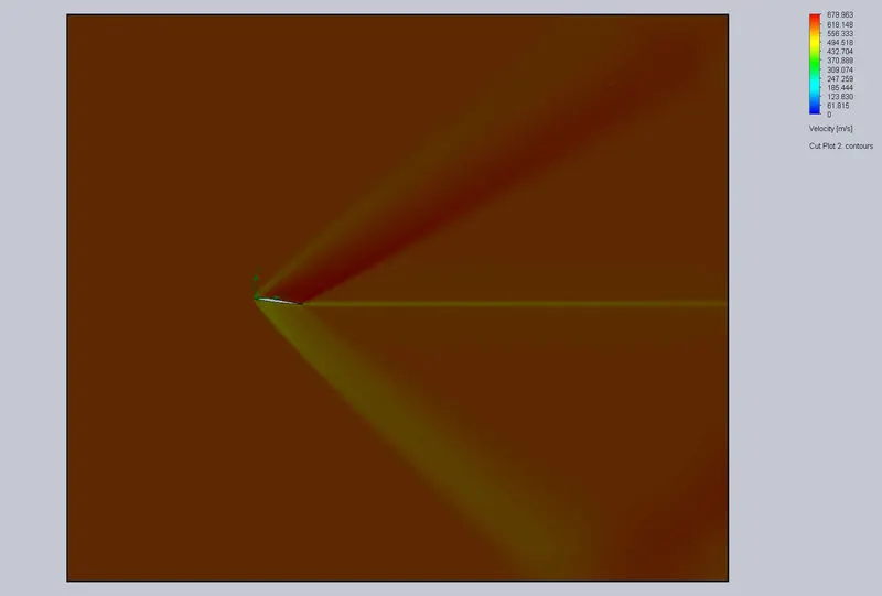
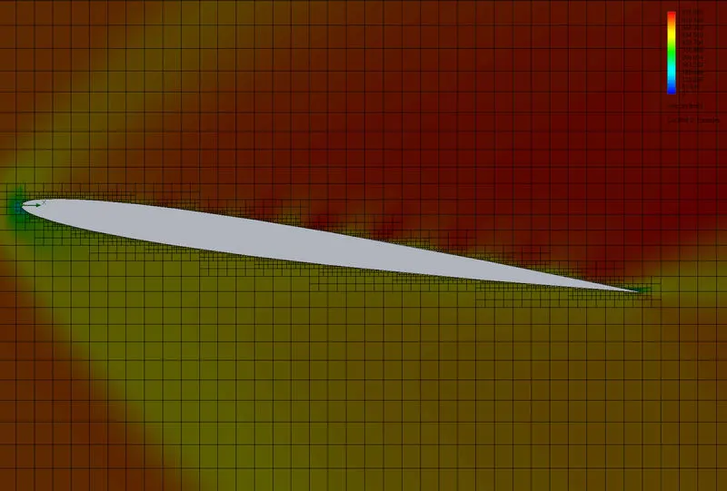
- For 10° angle of attack
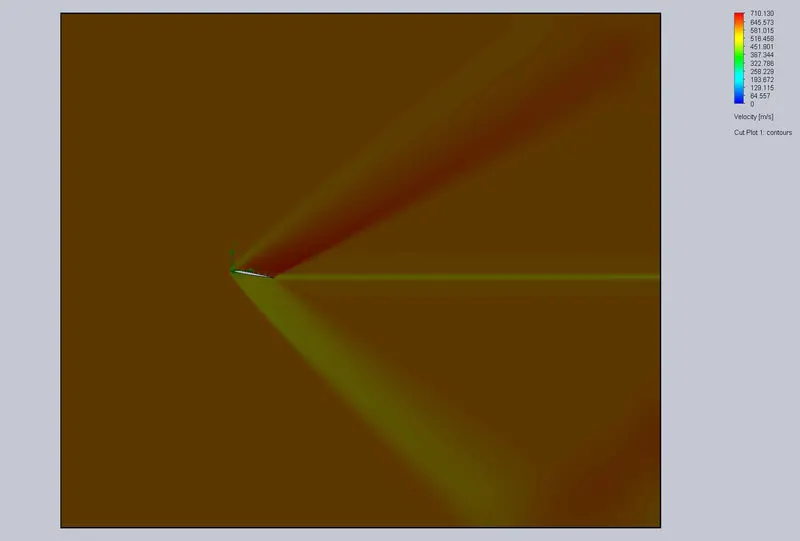
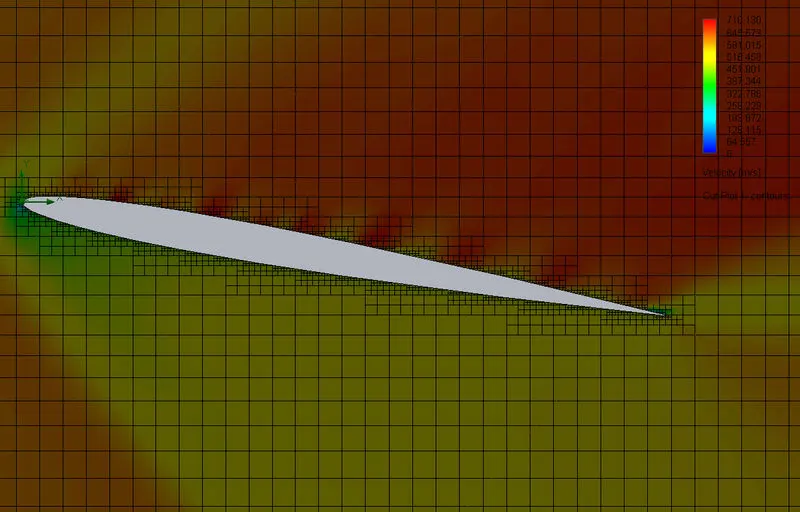
Form velocity contours, it can be observed that as the angle of attack is increased, the velocity above the airfoil is increasing and velocity below the airfoil is decreasing by comparing the colours with side colour panel.
Pressure Contours:
- For 0° angle of attack
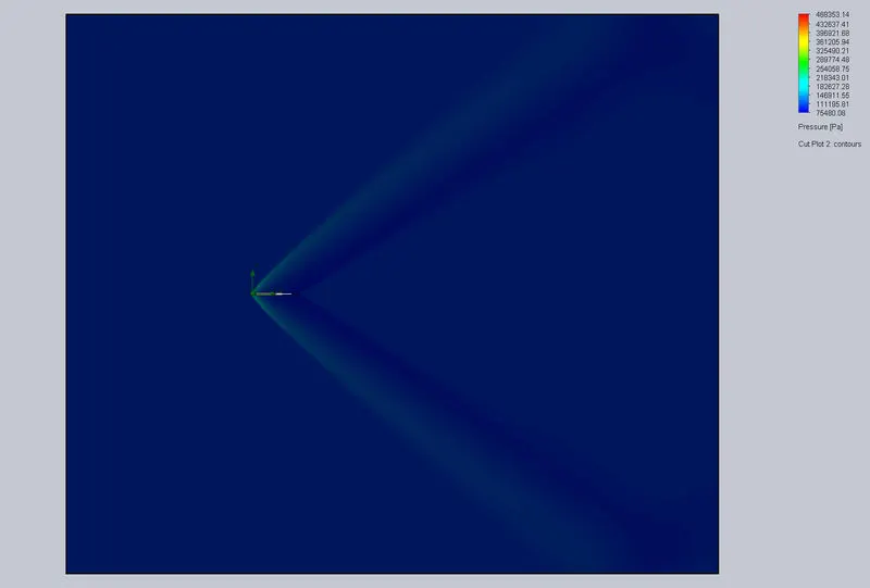
- For 2° angle of attack
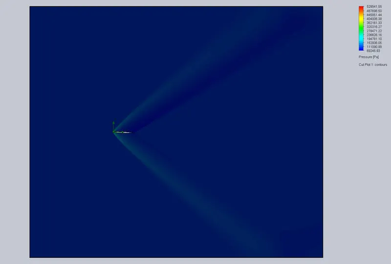
- For 4° angle of attack
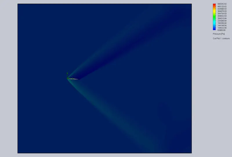
- For 6° angle of attack
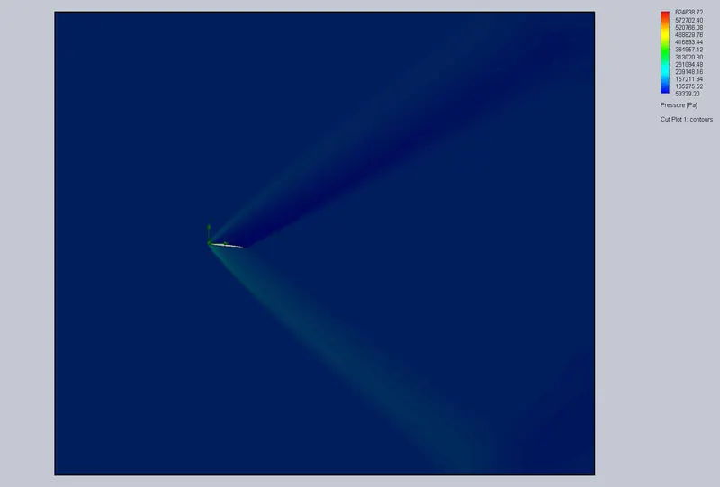
- For 8° angle of attack
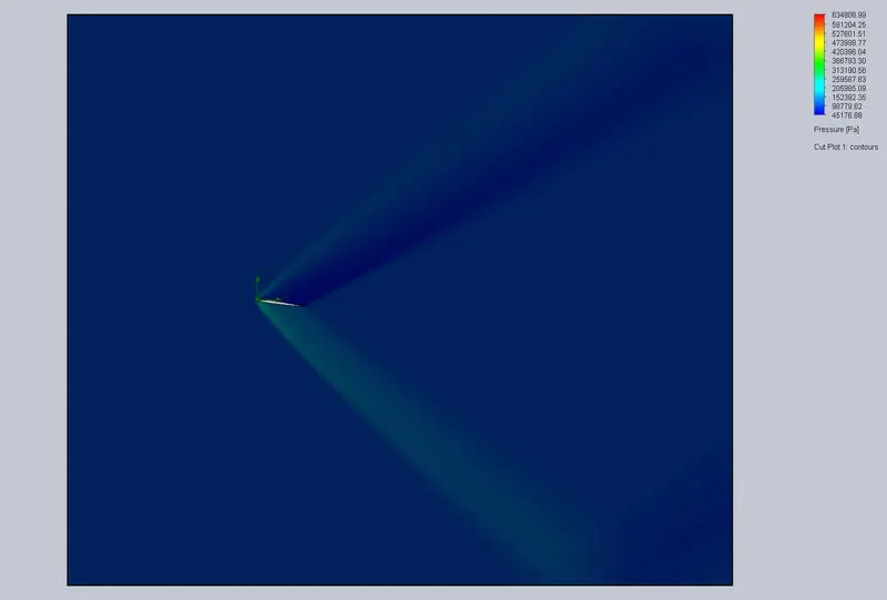
- For 10° angle of attack
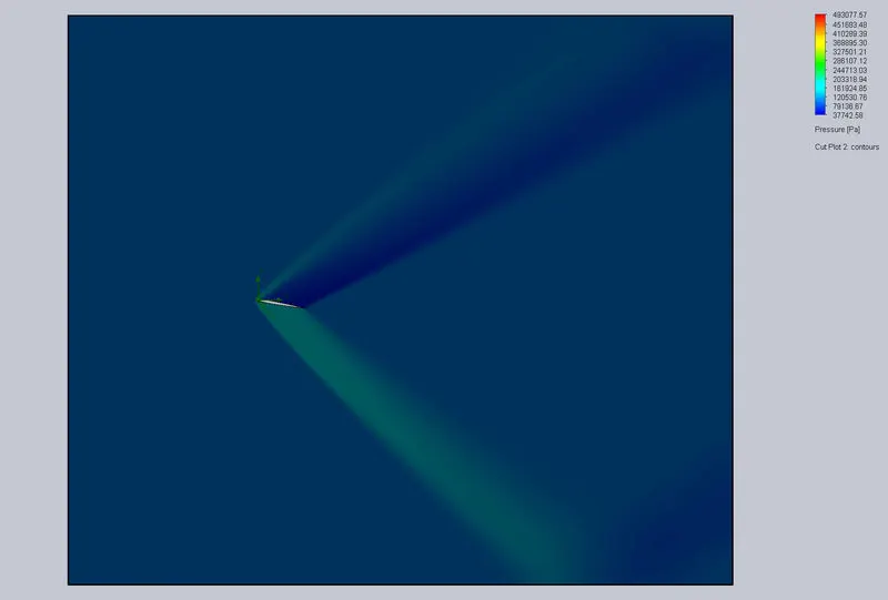
Form pressure contours, it can be observed that as the angle of attack is increased, the pressure above the airfoil is decreasing and pressure below the airfoil is increasing by comparing the colours with side colour panel.
Drag & Lift Force
- For 0° angle of attack
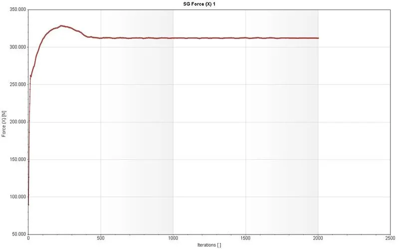
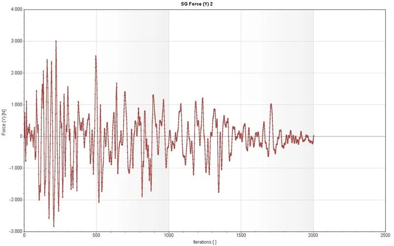
- For 2° angle of attack
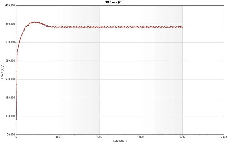
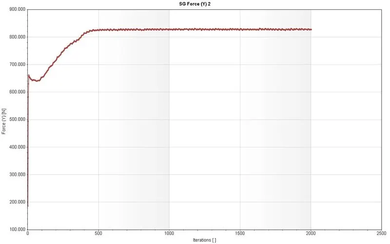
- For 4° angle of attack
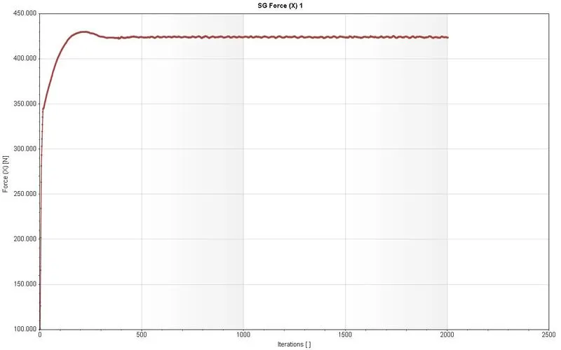
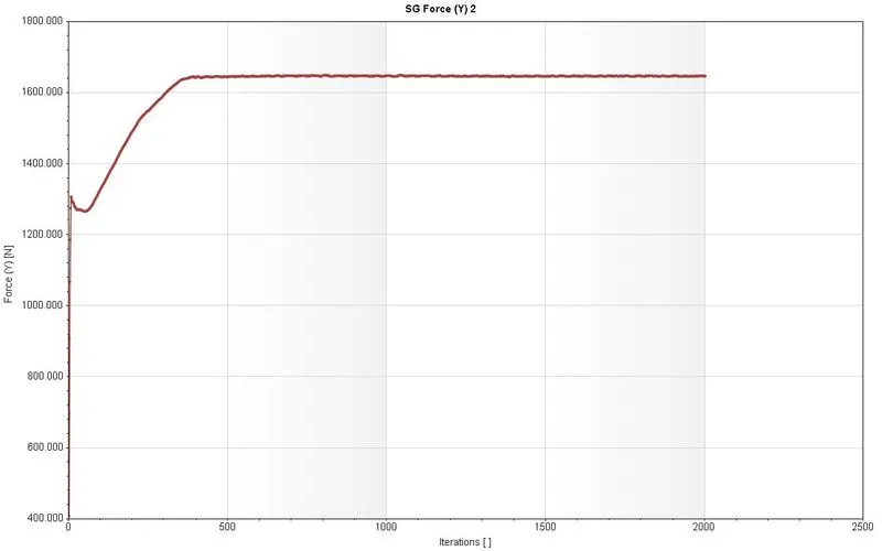
- For 6° angle of attack
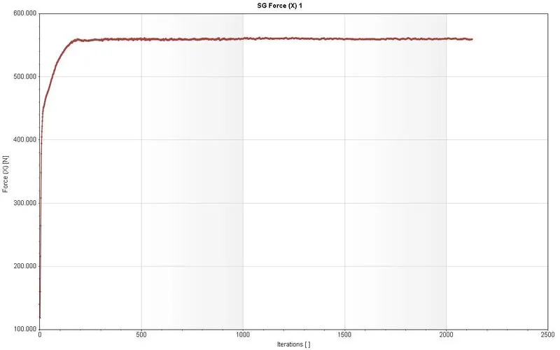
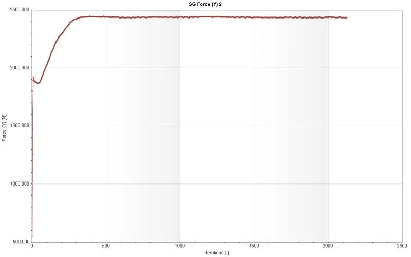
- For 8° angle of attack
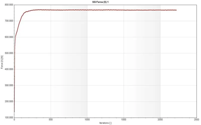
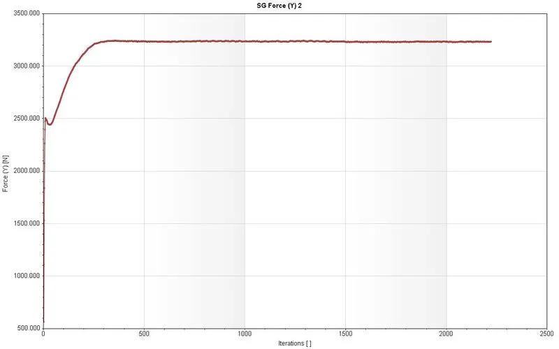
- For 10° angle of attack
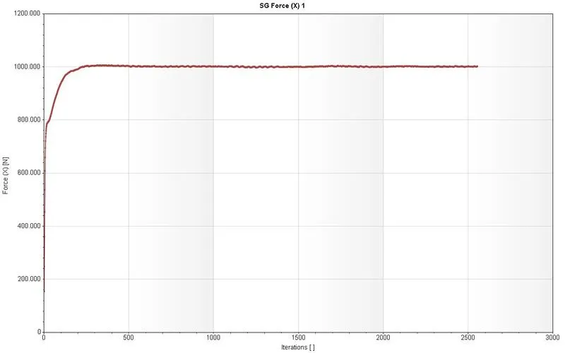
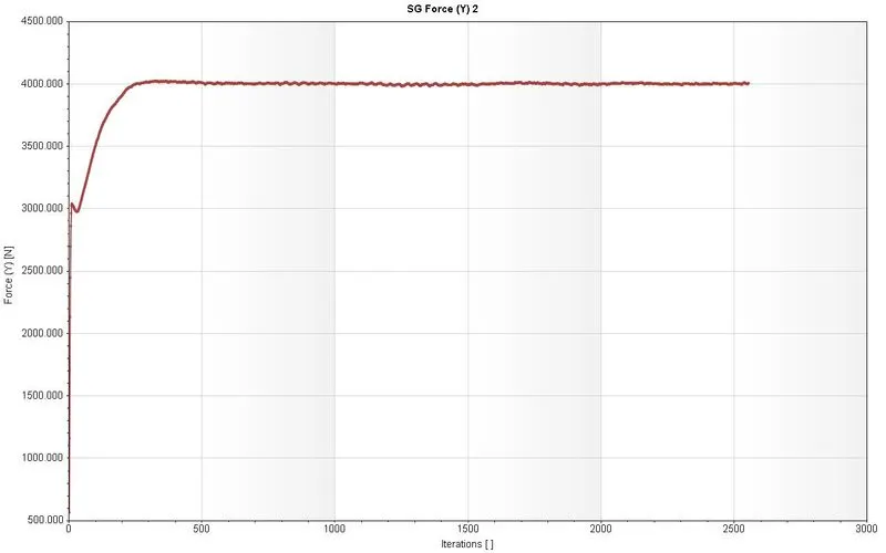
For 0° angle the lift force is fluctuating, but as the angle of attack is increased the plot gets refined and increasing and approximately become stable. The average values of lift and drag force also increasing as increase in angle of attack.
| Angle of Attack | Drag Force (N) | Lift Force (N) |
| 0 | 312.123 | -0.0764931 |
| 2 | 341.857 | 827.906 |
| 4 | 423.911 | 1646.31 |
| 6 | 559.754 | 2435.75 |
| 8 | 767.87 | 3232.77 |
| 10 | 1001.22 | 4002.59 |
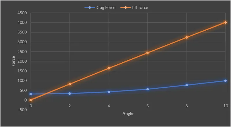
From above plot, it observed that there is significant increase in Lift force the Drag force.
Conclusion
The concept of Flow over an Airfoil simulation for different Angle of Attack using the SolidWorks has been properly implemented by creating the horizontal NACA0017 airfoil and doing simulation, and concluding the increase in Lift and Drag force due to increase in angle of attack.