Photo Realistic Rendering
TITLE OF THE PROJECT
Design, Assembly and Rendering of an American Chopper Motorcycle using Solidworks.
OBJECTIVE
- The objective of this project is used to create a model of different parts of the Chopper using Solidworks.
- To assemble the different parts modeled for the chopper.
- To create a Photorealistic model of the chopper and Render the model using Solidworks Photoview 360 or Solidworks visualize.
INTRODUCTION
A American Chopper is a type of custom motorcycle which emerged in the US state of California in the late 1950s. A chopper employs radically modified steering angles and lengthened forks for a stretched-out appearance. They can be built from an original motorcycle which is modified ("chopped") or built from scratch. Some of the characteristic features of choppers are long front ends with extended forks often coupled with an increased rake angle, hardtail frames (frames without rear suspension), very tall "ape hanger" or very short "drag" handlebars, lengthened or stretched frames, and larger than stock front wheels.The "sissy bar", a set of tubes that connect the rear fender with the frame, and which are often extended several feet high, is a signature feature on many choppers.
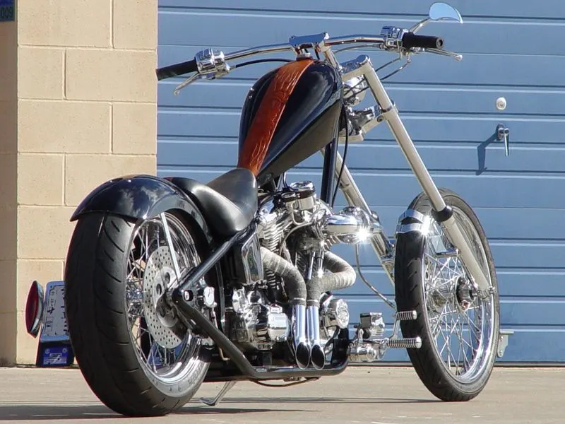
FIG 1-Example of American Chopper Bike
DESIGN METHODOLOGY
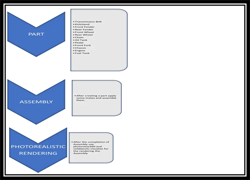
FIG 2-Design Methodology Flowchart
DESCRIPTION
Explained all the part given below which are the part of the assembly and also mentioned features which are used in assembly in Solidworks designing.
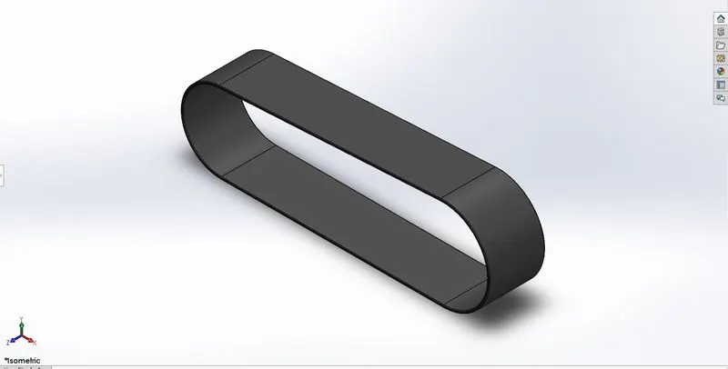
1-TRANSMISSION BELT
A belt drive is a transmission system that uses a flexible strip to transfer power. The turning disk is connected by a belt drive to the electric motor. A rubber belt drive is used to transfer power from one pulley to another. A belt drive is a transmission system that uses a flexible strip to transfer power.
The primary purpose of belt drives is to transmit power from one shaft to another with the help of a thin inextensible band that runs over two pulleys. These pulleys can rotate at the same or different speeds. The mechanical power or rotary motion is transmitted from the driving pulley to the driven pulley.
TOOLS USED
SKETCH TOOLS:
- 3 Point arc
- Line
- Offset
FEATURES:
- Boss extrude
- Fillet
- Appearance
2-KICKSTAND
The earliest known kickstand was designed by Albert Berruyer in 1869, and since then kickstands have been independently reinvented many times. It was mounted below the handlebars, so was much longer than more recent designs. A shorter model was patented by Eldon Henderson in 1926.In the 1930s, a "smaller, more convenient" kickstand was developed by Joseph Paul Treen.
In 1891, Pardon W, Tillinghast patented a design for a stand which was mounted on the pedal, but folded up flat under the pedal when not in use.
Kickstands on bicycles fell out of fashion in the 1970s, as the bicycles became lighter, and many riders were concerned about extra weight.
A kickstand is a device on a bicycle or motorcycle that allows the bike to be kept upright without leaning against another object or the aid of a person. A kickstand is usually a piece of metal that flips down from the frame and makes contact with the ground. It is generally located in the middle of the bike or towards the rear. Some touring bicycles have two: one at the rear, and a second in the front.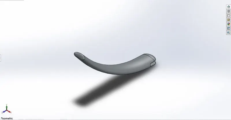
TOOLS USED
SKETCH TOOLS:
- Ellipse
- Spline
- Line
- Center rectangle
- Circle
FEATURES:
- Loft
- Dome
- Split
- Extruded cut
- Boss extrude
- Fillet
- Appearance
3-FRONT FENDER
Fender is the American English term for the part of an automobile, motorcycle or other vehicle body that frames a wheel well (the fender underside). Its primary purpose is to prevent sand, mud, rocks, liquids, and other road spray from being thrown into the air by the rotating tire. Fenders are typically rigid and can be damaged by contact with the road surface.
Sticky materials, such as mud, may adhere to the smooth outer tire surface, while smooth loose objects, such as stones, can become temporarily embedded in the tread grooves as the tire rolls over the ground. These materials can be ejected from the surface of the tire at high velocity as the tire imparts kinetic energy to the attached objects. For a vehicle moving forward, the top of the tire is rotating upward and forward, and can throw objects into the air at other vehicles or pedestrians in front of the vehicle.
In modern Indian and Sri Lankan English usage, the wing is called a mudguard. However, the term mudguard appears to have been in use in the U.S. at one point. The American author E.B. White, in his October 1940 Harper's essay "Motor Cars", refers to "...mudguards, or 'fenders' as the younger generation calls them.
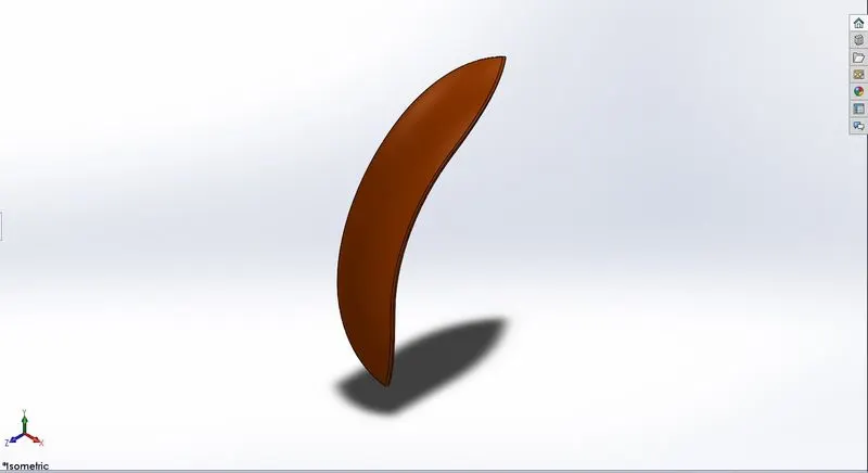
TOOLS USED
SKETCH TOOLS:
- 3 Point arc
- Sketch offset
- Line
- Spline
- Dynamic mirror entities
FEATURES:
- Revolve
- Split
- Fillet
- Appearance
4-REAR FENDER
Fender is the American English term for the part of an automobile, motorcycle or other vehicle body that frames a wheel well (the fender underside). Its primary purpose is to prevent sand, mud, rocks, liquids, and other road spray from being thrown into the air by the rotating tire. Fenders are typically rigid and can be damaged by contact with the road surface.
Sticky materials, such as mud, may adhere to the smooth outer tire surface, while smooth loose objects, such as stones, can become temporarily embedded in the tread grooves as the tire rolls over the ground. These materials can be ejected from the surface of the tire at high velocity as the tire imparts kinetic energy to the attached objects. For a vehicle moving forward, the top of the tire is rotating upward and forward, and can throw objects into the air at other vehicles or pedestrians in front of the vehicle.
In modern Indian and Sri Lankan English usage, the wing is called a mudguard. However, the term mudguard appears to have been in use in the U.S. at one point. The American author E.B. White, in his October 1940 Harper's essay "Motor Cars", refers to "...mudguards, or 'fenders' as the younger generation calls them.
Sporty-styled or racing motorcycles sometimes come with, or have added as an aftermarket accessory, a "hugger" rear fender, attached to the rear swingarm and very close to the tire, rather than attached to the rear subframe and away from the tire.Conversely, the practice of removing the front fender and reducing the size of the rear fender produced the bobber customization style of the 1950s onwards.
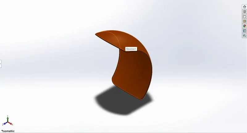
TOOLS USED
SKETCH TOOLS:
- 3 Point arc
- Offset
- Line
- Spline
- Dynamic mirror entities
FEATURES:
- Revolve
- Split
- Fillet
- Shell
- Appearance
5-CHAIN
A chain is a serial assembly of connected pieces, called links, typically made of metal, with an overall character similar to that of a rope in that it is flexible and curved in compression but linear, rigid, and load-bearing in tension. A chain may consist of two or more links. Chains can be classified by their design, which can be dictated by their use:
Those designed for lifting, such as when used with a hoist; for pulling; or for securing, such as with a bicycle lock, have links that are torus shaped, which make the chain flexible in two dimensions (the fixed third dimension being a chain's length). Small chains serving as jewellery are a mostly decorative analogue of such types.
chain, series of links, usually of metal, joined together to form a flexible connector for various purposes, such as holding, pulling, hoisting, hauling, conveying, and transmitting power.
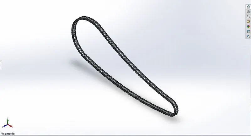
TOOLS USED
SKETCH TOOLS:
- 3 Point arc
- Circle
- Trim entities
- Line
- Insert block
FEATURES:
- Boss extrude
- Fillet
- Curve driven pattern
- Mirror
- Appearance
6-OIL TANK
An oil storage tank is a container or reservoir that temporarily holds oil in the various stages of processing into other oil products, or before it is used or consumed. Stores the oil for lubrication and cooling purposes.
This tank is placed right below the rider seat on top of the gearbox.
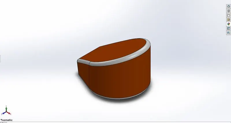
TOOLS USED
SKETCH TOOLS:
- Line
- 3 Point arc
FEATURES:
- Boss extrude
- Combine
- Fillet
- Shell
- Appearance
7-PEDAL
Pedal,the part of a automobile that the rider pushes with their foot to propel the vehicle.
Foot controls
- Gear selector
Gears enable you to match engine power to road speed. You will use a low gear to move off and a higher gear once you’ve gained speed.
Changing smoothly through the gears is a skill that will improve with practice.
The gear selector is usually on the left side of the motorcycle, just in front of the footrest.
The neutral position is when no gear is engaged. Most motorcycles have a green warning light to show when the gears are in neutral.
Gears are selected by lifting or pushing down the gear lever with your foot. The positions and number of gears vary with the make of motorcycle.
- Rear brake pedal
This pedal is usually on the right side of the motorcycle, just in front of the footrest. Some automatic motorcycles have the rear brake lever on the left handlebar.
- Kick-start lever
This is usually on the right side of the motorcycle, near the footrest.
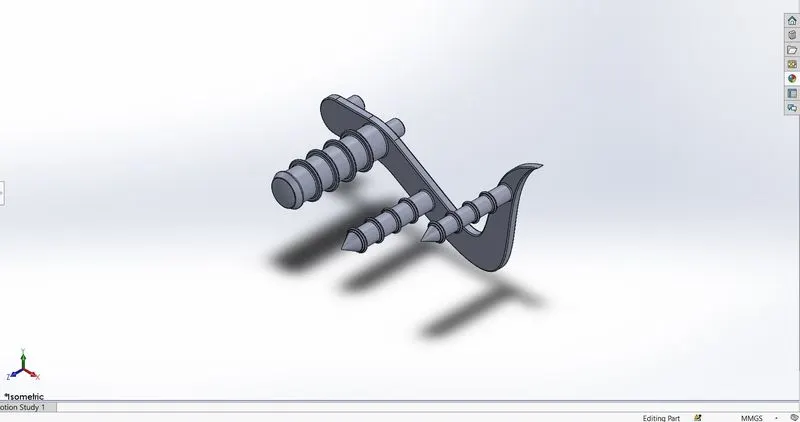
TOOLS USED
SKETCH TOOLS:
- Line
- 3 Point arc
- Circle
- Spline
- Sketch fillet
FEATURES:
- Boss extrude
- Fillet
- Revolve
- Dome
- Chamfer
- Linear Pattern
- Appearance
8-FRONT WHEEL
The first commercial motorcycles were built like bicycles, with wire wheels as bicycles had traditionally been fitted with. The Steffey motorcycle in 1902, essentially a bicycle with a two-stroke engine attached, used wooden, rims with wire spokes.This style of wheel evolved into a stouter motorcycle-specific wheel, still with spokes, up to the 1960s and beyond.
In April, 1922, Borrani started production of motorcycle wheels with an aluminium rim.
Although cast wheels had already been used on automobiles previously, it was not until the 1927 that the Böhmerland, a motorcycle built in Czechoslovakia was fitted with cast wheels.
BMW patented a spoked wheel that cross ran the spokes onto the outside of the rim, allowing the use of tubeless tires.
By the late 2000s, a number of materials and designs in addition to traditional spoked wheels were available, including cast, spun or forged aluminum; cast or forged magnesium; and single-layup or composite carbon fiber.
The head tube is the short tube at the front of the frame, which connects the handlebars to the wheel fork. It contains the headset which allows us to steer the front wheel via the handlebars.
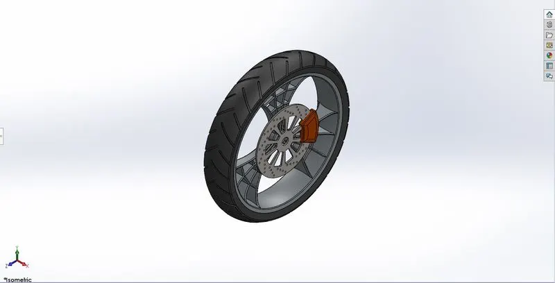
TOOLS USED
SKETCH TOOLS:
- Line
- 3 Point arc
- Mid point line
- Spline
- Circle
- Sketch fillet
- Trim entities
- Extend entities
- Linear sketch pattern
- 3 Point centre rectangle
FEATURES:
- Revolve
- Boss extrude
- Cut extrude
- Cut revolve
- Circular pattern
- Combine
- Fillet
- Chamfer
- Appearance
9-REAR WHEEL
Rear wheel is a form of engine and transmission layout used in motor vehicles, in which the engine drives the rear wheels only. Until the late 20th century, rear-wheel drive was the most common configuration for automobile. Most rear-wheel drive vehicles feature a longitudinally-mounted engine at the front of the automobile.
Since the back two wheels help the motorcycle accelerate and the front two wheels are responsible for steering the vehicle, the power coming from the rear allows for a faster driving experience.
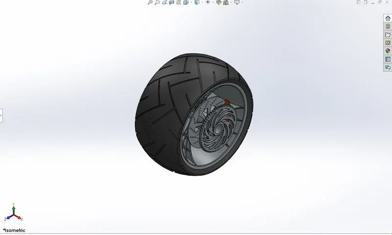
TOOLS USED
SKETCH TOOLS:
- Line
- 3 Point arc
- Sketch fillet
- Spline
- Mid point line
- Circle
- Trim entities
- Extend entities
- 3 Point centre rectangle
FEATUTES:
- Revolve
- Boss extrude
- Cut extrude
- Cut revolve
- Circular pattern
- Combine
- Fillet
- Chamfer
- Appearance
10-FRONT FORK
A Front fork or motorcycle fork connects a motorcycle's front wheel and axle to its frame, typically via a yoke, also known as a triple clamp, which consists of an upper yoke joined to a lower yoke via a steering stem, a shaft that runs through the steering head, creating the steering axis. Most forks incorporate the front suspension and front brake, and allow the front wheel to rotate about the steering axis so that the bike may be steered. Most handlebars attach to the top clamp in various ways, while clip-on handlebars clamp to the fork tubes, either just above or just below the upper triple clamp.
The fork and its attachment points on the frame establish the critical geometric parameters of rake and trail, which play a major role in defining how a motorcycle handles and dives during braking.[1] While the standard telescopic fork arrangement is found with few major differences among mainstream street motorcycles since the 1970s, historically there have been many variations, including trailing or leading link, springer, Earles, girder, and others, as well as non-fork steering such as hub-center steering.
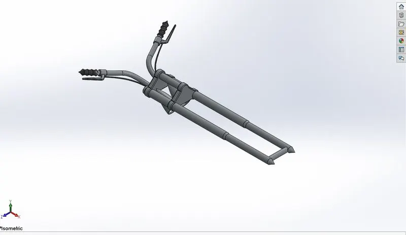
TOOLS USED
SKETCH TOOLS:
- Line
- Circle
- Trim entities
- 3 Point arc
- Spline
FEATURES:
- Revolve
- Boss extrude
- Fillet
- Line pattern
- Extruded cut
- Dome
- Revolve cut
- Body-move/copy
- Projected curve
- Sweep
- Reference geometry plane
- Mirror
- Combine
- Appearance
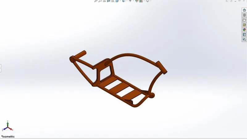
11-CHASSIS
A Chassis or motorcycle frame is a motorcycle's core structure. It supports the engine, provides a location for the steering and rear suspension, and supports the rider and any passenger or luggage. Also attached to the frame are the fuel tank and battery. At the front of the frame is found the steering head tube that holds the pivoting front fork, while at the rear there is a pivot point for the swingarm suspension motion. Some motorcycles include the engine as a load-bearing stressed member; while some other bikes do not use a single frame, but instead have a front and a rear subframe attached to the engine.
A motorcycle's chassis or frame forms its skeleton. All the components of a motorcycle, like the suspension, wheels, fuel tank, seats, handlebars etc, are attached to this base structure which lends a motorcycle its strength and ability to handle well.
TOOLS USED
SKETCH TOOLS:
- Circle
- Line
- Spline
- 3 Point arc
- Trim entities
FEATURES:
- Projected curve
- Sweep
- Mirror
- Boss extrude
- Cut extrude
- Chamfer
- Fillet
- Reference geometry plane
- Dome
- Split
- Combine
- Revolve
- Appearance
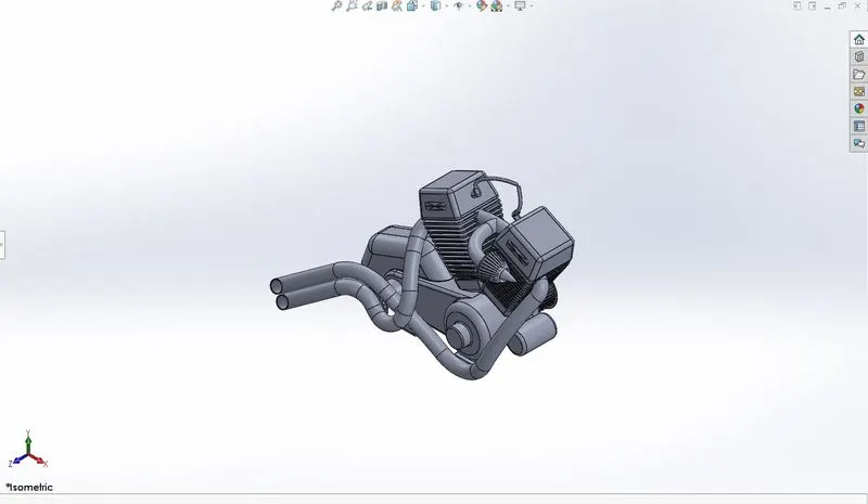
12-ENGINE
The first motorcycles were powered by steam engines. The earliest example is the French Michaux-Perreaux steam velocipede of 1868. This was followed by the American Roper steam velocipede of 1869, and a number of other steam powered two and three wheelers, manufactured and sold to the public on through the early 20th century.
A motorcycle engine is an engine that powers a motorcycle. Motorcycle engines are typically two-stroke or four-stroke internal combustion engines, but other engine types, such as Wankels and electric motors, have been used.
Although some mopeds, such as the Velosolex, had friction drive to the front tire, a motorcycle engine normally drives the rear wheel, power being sent to the driven wheel by belt, chain or shaft. Historically, some 2,000 units of the Megola were produced between 1921 and 1925 with front wheel drive,and the modern Rokon, an all terrain motorcycle with both wheels driven, has been produced since 1960.
Most engines have a gearbox with up to six or even 7 ratios. Reverse gear is occasionally found on heavy tourers, for example the Honda GL1600, and sidecar motorcycles, such as the Ural. The rider changes gears on most motorcycles using a foot-pedal and manual clutch, but early models had hand-levers. More recently, some have automatic or semi-automatic gearboxes, and some using CVT transmission.
Outside the United States, engine capacities typically ranged from about 50 cc to 650 cc; but in Europe since 1968 motorcycles with larger capacities have become common, ranging as high as the Triumph Rocket 3's 2,300 cubic centimetres (140 cu in) engine. In the United States, V-twin engined motorcycles with capacities of 850 cc or more have been the norm since the 1920s.
TOOLS USED
SKETCH TOOLS:
- Sketch picture
- Circle
- Line
- Construction line
- Circular sketch pattern
- Trim entities
- Centre rectangle
- Sketch fillet
- 3 Point centre rectangle
- 3 Point arc
- Spline
- Mid point line
FEATURES:
- Boss extrude
- Fillet
- Revolve
- Reference geometry plane
- Circular pattern
- Dome
- Cut extrude
- Chamfer
- Fillet
- Line pattern
- Mirror
- Split
- Sweep
- Combine
- Projected curve
- Composite curve
- Appearance
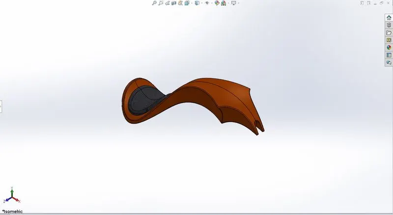
13-GAS TANK
A Gas tank or fuel tank (also called a petrol tank) is a safe container for flammable fluids. Though any storage tank for fuel may be so called, the term is typically applied to part of an engine system in which the fuel is stored and propelled (fuel pump) or released (pressurized gas) into an engine. Fuel tanks range in size and complexity from the small plastic tank of a butane lighter to the multi-chambered cryogenic Space Shuttle external tank.
Typically, a Gas tank or fuel tank must allow or provide the following:
Storage of fuel: the system must contain a given quantity of fuel and must avoid leakage and limit evaporative emissions.
Filling: the fuel tank must be filled in a secure way, without sparks.
Provide a method for determining level of fuel in tank, gauging (the remaining quantity of fuel in the tank must be measured or evaluated).
Venting (if over-pressure is not allowed, the fuel vapors must be managed through valves).
Feeding of the engine (through a pump).
Anticipate potentials for damage and provide safe survival potential.
This important component is often regarded as the ‘face’ of the motorcycle, and its shape, size and color are often considered determining factors in one’s first impressions of a bike’s design. Of course, the main function of the fuel tank is simply to hold fuel. However, it also provides a secure area for the knees to grip while riding, acting as an important point of contact between bike and rider. And when cleaning and polishing it on days not out riding, the tank can also be an object of affection that fosters a rider’s close relationship with his or her machine.
When thinking about fuel tanks, I’m sure I’m not the only one who’s been entranced by or taken pictures of the reflections seen in its curvaceous surface. Such memories leave an indelible impression, like fleeting delights that enrich our motorcycling lives.
TOOLS USED
SKETCH TOOLS:
- Sketch picture
- Spline
- Line
- Construction line
- 3 Point arc
- Trim entities
- Offset entities
FEATURES:
- Reference geometry plane
- Surface sweep
- Surface trim
- Projected curve
- Surface loft
- Boundary surface
- Mirror
- Surface knit
- Split line
- Surface extrude
- Fillet
- Cut sweep
- Shell
- Appearance
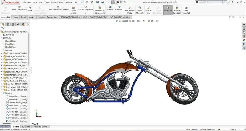
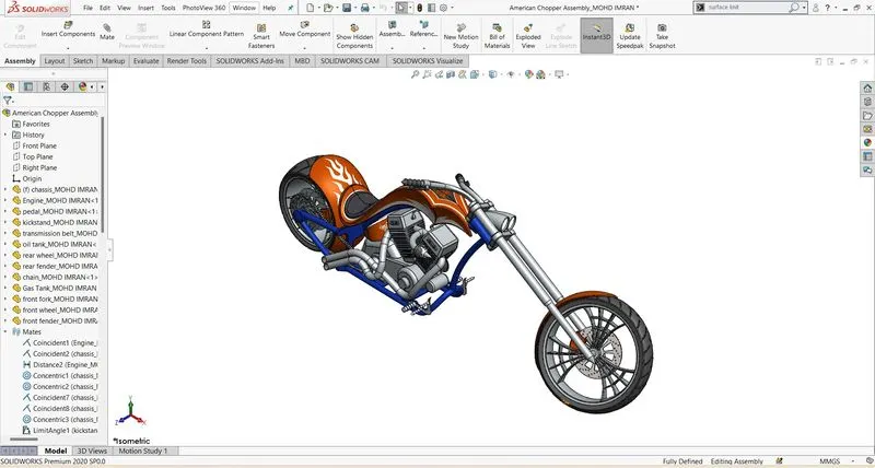
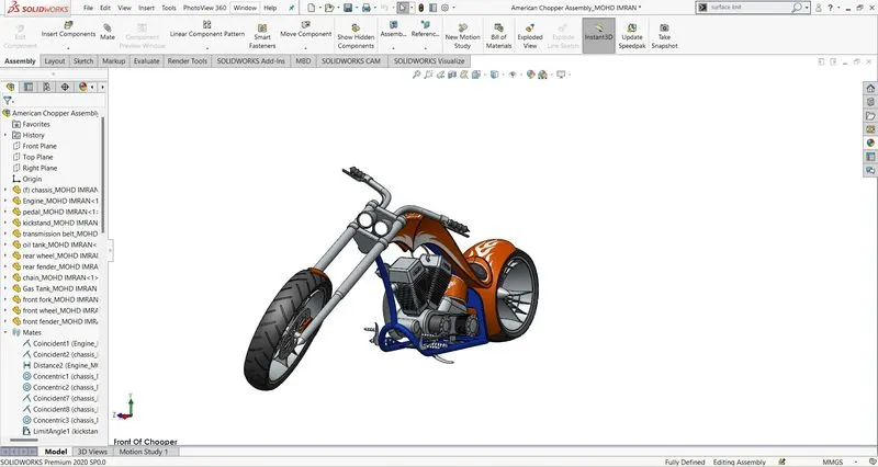
ASSEMBLY
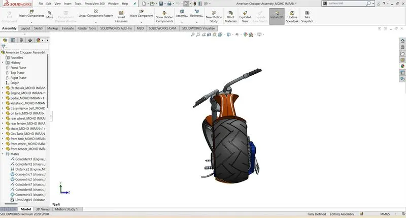
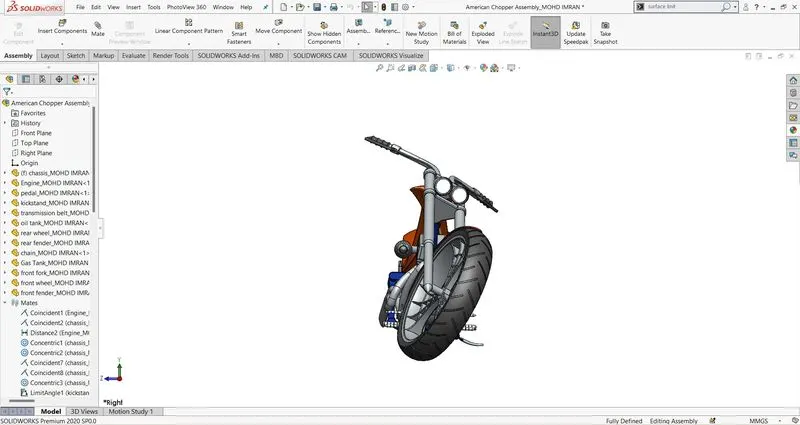
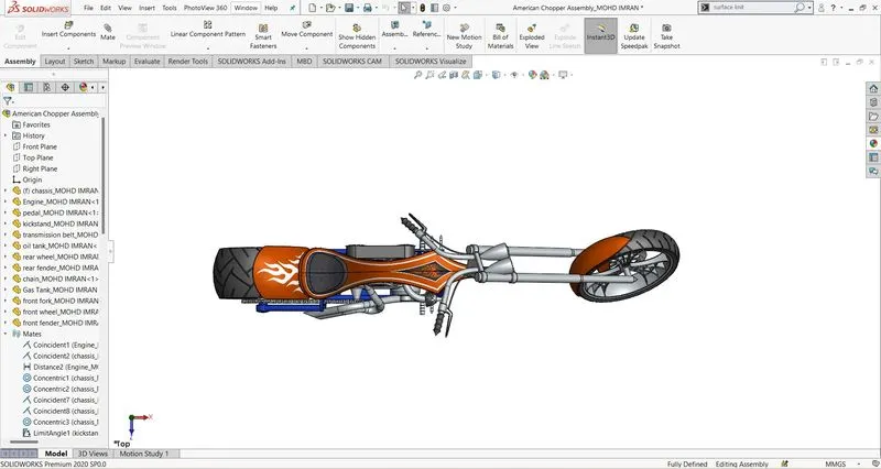
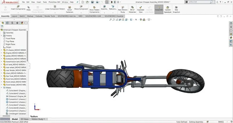
After the design of all parts of American chopper successfully assemble all the parts in Solidworks.
For the assembly go to the menu bar and click on file
File ≥New≥Assembly
Then insert the parts in (part/assembly to insert) section after that apply appropriate mates and assemble aal the parts.
Mates those are apply in assembly of American chopper bike are given below.
- Coincident mate between front plane of engine and midplane of chassis
- Coincident mate between lower face of engine and upper face of chassis
- Distance mate between chassis and engine face(20mm)
- Concentric mate between chassis and pedal face
- Coincident mate between chassis and pedal face
- Coincident mate between chassis and kickstand face
- Concentric mate between chassis and kickstand face
- Limit angle mate between right plane kickstand and chassis face(limit angle=0deg,maximum value=75deg,minimum value=0deg)
- Concentric mate edge of the pulley and inner face of transmission belt
- Width mate transmission belt and pulley
- Angle mate between transmission belt and engine(7deg)
- Coincident mate between engine and oil tank face
- Coincident mate between engine and oil tank edge
- Coincident mate between midplane of chassis and midplane of oil tank
- Concentric mate between chassis and rear wheel
- Coincident mate between midplane of chassis and right plane of rear wheel
- Parallel mate between right plane of chassis and front plane of rear wheel
- Concentric mate between rear fender and rear wheel edge
- Coincident mate between midplane of chassis and midplane of rear fender
- Parallel mate between right plane chassis and vertical plane of rear fender
- Width mate between chain and rear wheel
- Concentric mate between edge of rear wheel sprocket and arc of the chain
- Parallel mate between bottom plane of chassis and centre plane of chain
- Distance mate between reference geometry plane2 of chassis and front plane of gas tank(5mm)
- Coincident mate between bottom plane of chassis and bottom plane of gas tank
- Coincident mate between midplane of chassis and midplane of gas tank
- Concentric mate between front fork and chassis
- Width mate between chassis and front fork
- Limit angle mate between front plane of front fork and midplane of chassis(limit angle=29.99deg,maximum value=30deg,minimum value=-30deg)
- Parallel(rename as position) mate between midplane of chassis and front plane of the front fork
- Concentric mate between front fork and front wheel
- Coincident mate between midplane of front fork and right plane of front wheel
- Coincident mate between vertical plane of front fork and front plane of front wheel
- Coincident mate between vertical plane of front fork and vertical plane of front fender
- Coincident mate between top plane of front wheel and centre plane of front fender
- Coincident mate between right plane of front wheel and midplane of front fender
- Tangent mate between rear wheel and top plane
- Tangent mate between front wheel and top plane
- Tangent mate between kickstand and top plane
- Tangent mate between front wheel and top plane
- Mirror pedal
RENDERING:
We have two rendering in Solidworks Photoview 360 and Solidworks visualize and rendering is successfully done by using Photoview 360 and Solidworks visualize.
PHOTOVIEW 360
For rendering in photoview 360 go to in menu bar and click on option icon then click add in and select photoview 360.
In photoview 360 we have many features in context menu bar for rendering and those are given below.
1-Edit appearance
Edits the appearance of entities in the model.When you edit an appearance assigned to a group of entities,the appearance updates for all entities.You can edit appearance properties such as texture mapping and colors.
2-Copy appearance
Copies the appearance of one entities so you can paste it onto another using the paste appearance tool.Use this tool to copy appearances instead of recreating them.
For copy appearances use ctrl+shift+c key.
3-Paste appearance
Paste the appearance that you copy from one entity to others in the model.Pasted appearances retain all the customizations made in the edit appearance property manager.Use the appearance target pallete to target the pasted appearance to an entity.
For paste appearance use ctrl+shift+v key.
4-Edit scene
Edit the scene applied to the document.
5-Edit decal
Applies a decal to faces in a model.
6-Integrated preview
Displays the photoview 360 preview inside the solidworks graphic area.
7-Preview window
8-Final render
9-Render region
Defines a graphics window region to render(either preview or final render)
10-Scene illumination proof sheet
11-Options
Edit the photoview 360 rendering options.
12-Schedule render
Use the Schedule Render dialog box to perform a rendering at a specified time and save it to a file.
13-Recall last render
Uses of features that are used in rendering of American chopper bike in Photoview 360
- Edit appearance
- Edit scenes
- Edit decals
- Preview window
- Option
- Final render
- Schedule render
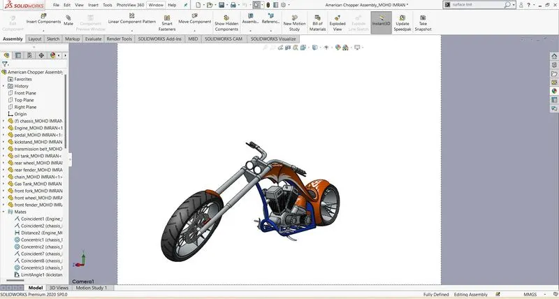
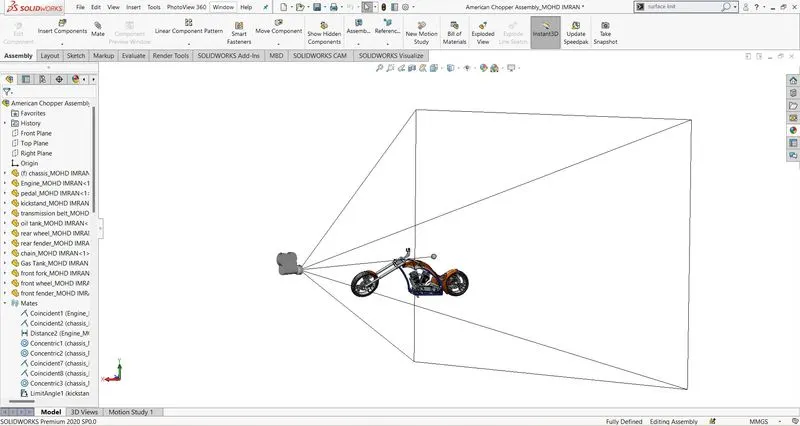
- Camera setup
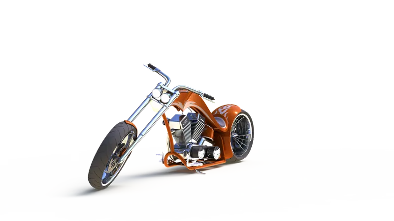
Fig-Isometric view of render image of american chopper bike
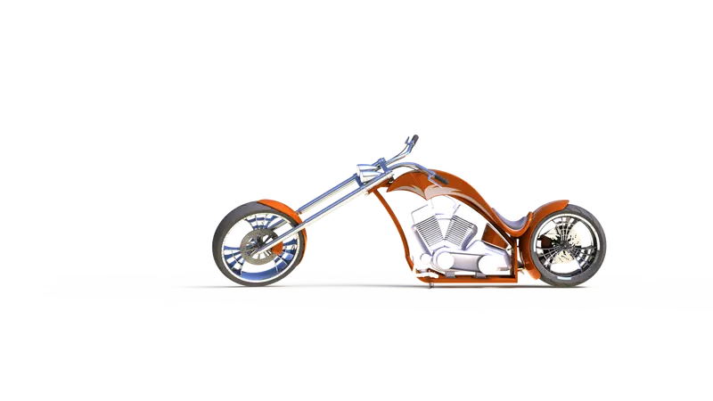
Fig-Front view of render image of american chopper bike
SOLIDWORKS VISUALIZE
SOLIDWORKS Visualize allows you to leverage your 3D CAD data to create photo-quality content in the fastest and easiest way you can–from images to animations, interactive web content, and immersive Virtual Reality. Bring your products to life. SOLIDWORKS Visualize is the “camera” for your CAD data.
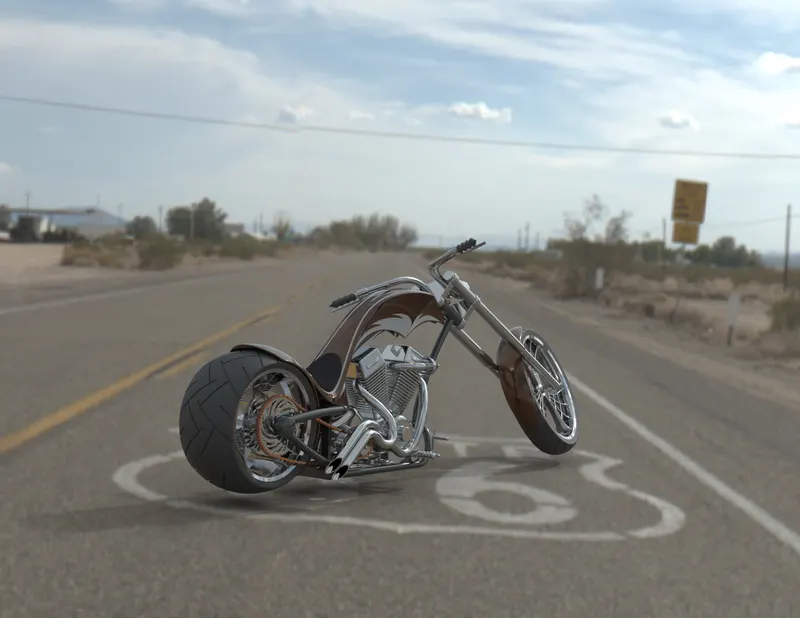
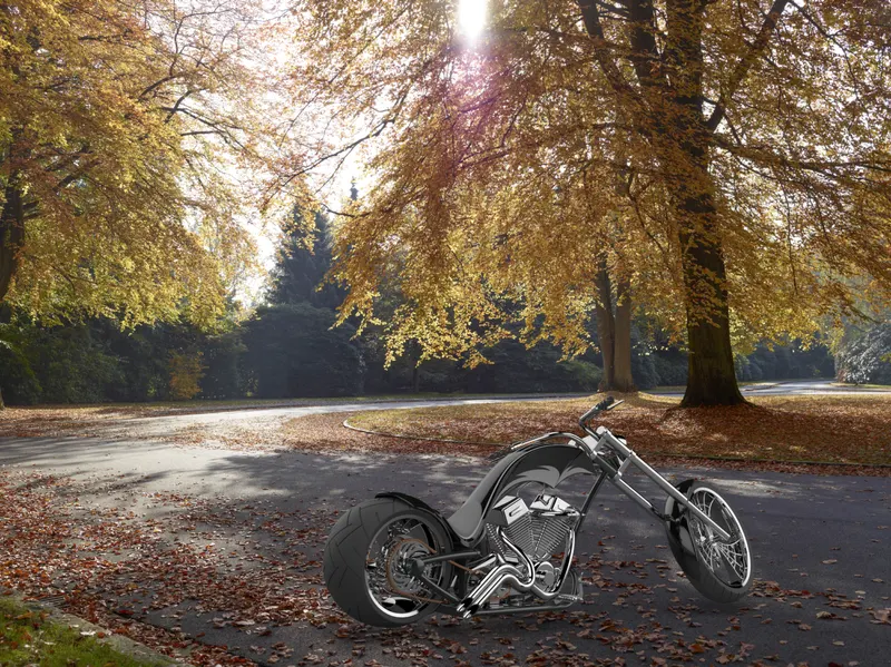
CONCLUSION
Design, Assembly and Rendering using of photoview 360 and solidworks visualize of an American Chopper Motorcycle using Solidworks 2020 successfully done.