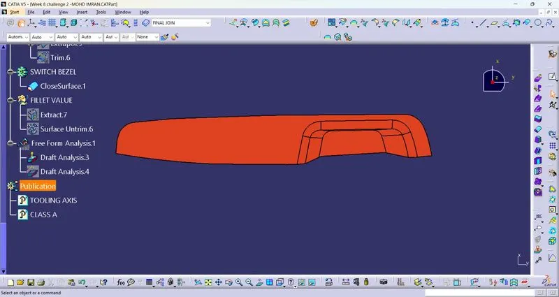
Week 8 - Challenge 2 - Switch Bezel Design
TITLE OF THE PROJECT
Switch Bezel Design
AIM
to Create the Switch Bezel Plastic component through the given Class-A surface.Create a Tooling axis and Draft analysis on the model.
INTRODUCTION
In the Switch Bezel Design Create the Switch Bezel Plastic component through the given Class-A surface. To begin with, the tooling axis for the given Class-A Surface should be created meeting the requirements of the draft angle and at the end perform the Draft analysis on the model.
OBJECTIVE
- Creation of tooling axis.
- Draft analysis of Class A Surface.
- Creation of B Surface by given Class A Surface.
- Creation of C Surface.
- Creation of solid part by using closed surface.
CREATION OF TOOLING AXIS
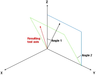
Tooling axis define as a
- Angle 1 about X, Angle 2 about Y: The tool axis is rotated an Angle 1 about the x-axis, then rotated an Angle 2 about the y-axis.
- Angle 1 about Z, Angle 2 about X: The tool axis is rotated an Angle 1 about the z-axis, then rotated an Angle 2 about the x-axis.
- Angle 1 about Y, Angle 2 about Z: The tool axis is rotated an Angle 1 about the y-axis, then rotated an Angle 2 about the z-axis.
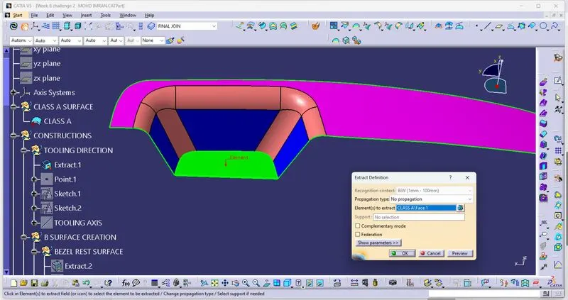
Extract the base part of the Switch Bezel.
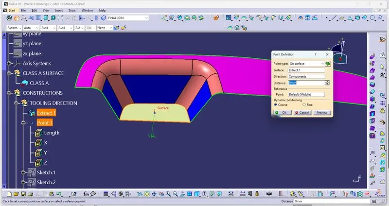
Create a point on the middle of the base.
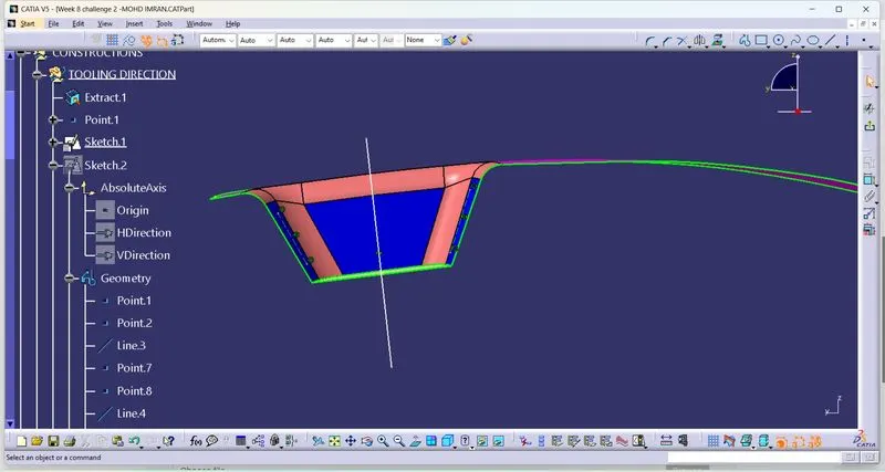
SKETCH1
Project the border of the both blue surfaces then create a line on the them then create a intersection line through both of the line.
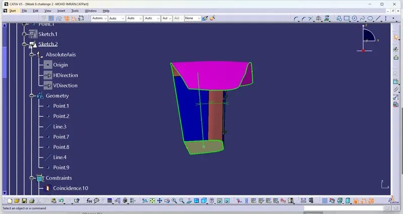
SKETCH2
Draw a line on the middle of the blue surface and draw second line start from the point which is created in the starting of the design then give the angle between both of the line is 6 degree.
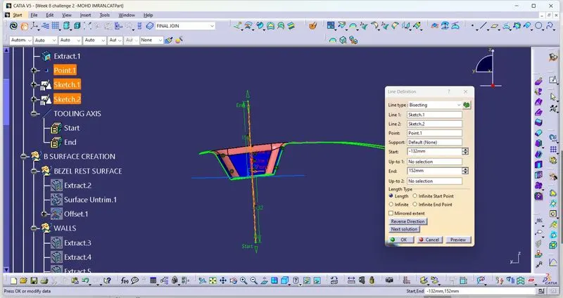
Bisect the line1 of sketch1 and line2 of sketch2 with each other.
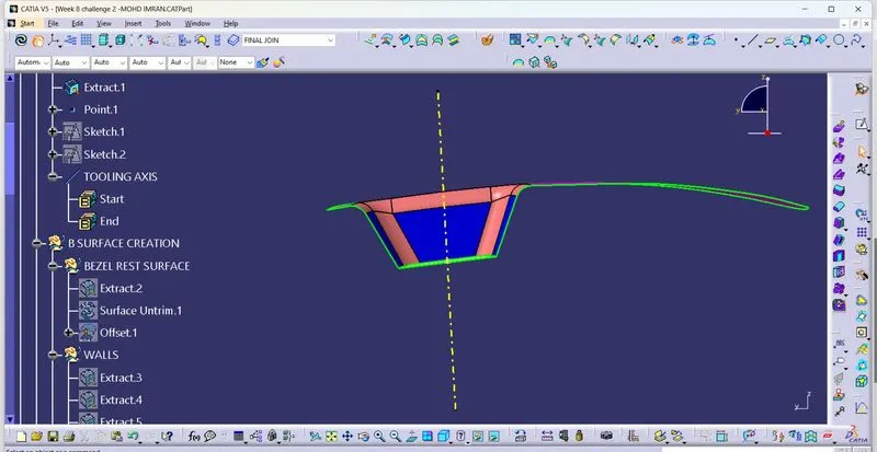
RESULT
Tooling Axis is created.
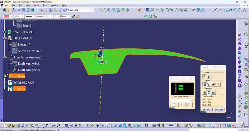
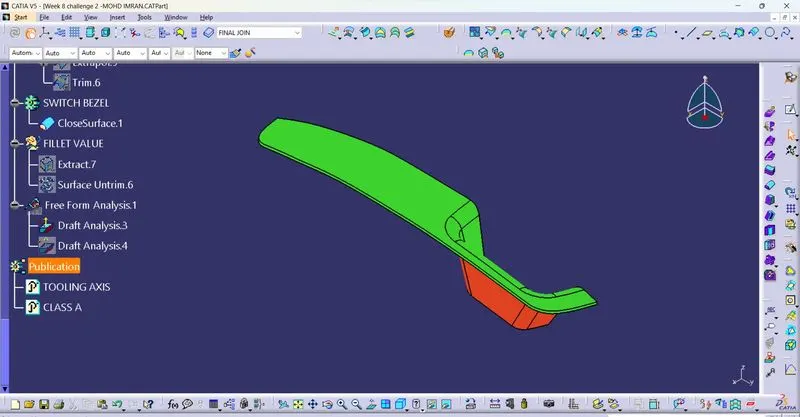
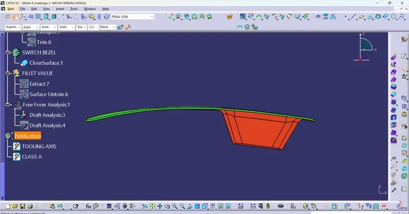
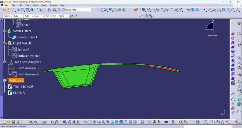
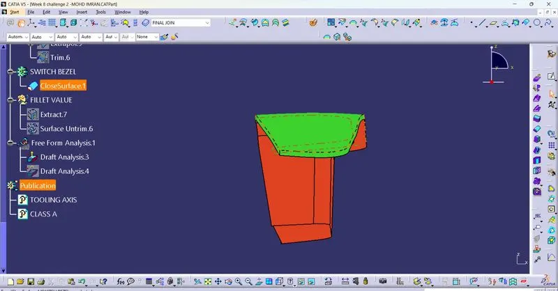
DRAFT ANALYSIS
- Go to insert< analysis< feature draft analysis.
- Align the tooling axis with the compass.
- Click on the surface and see that the surface is within the permissible limit of the draft values.
- The surface should be green and in the column proper value (3deg) should be inserted.
DRAFT ANALYSIS OF CALASS A SURFACE
DRAFT ANALYSIS OF FINAL PLASTIC COMPONENT
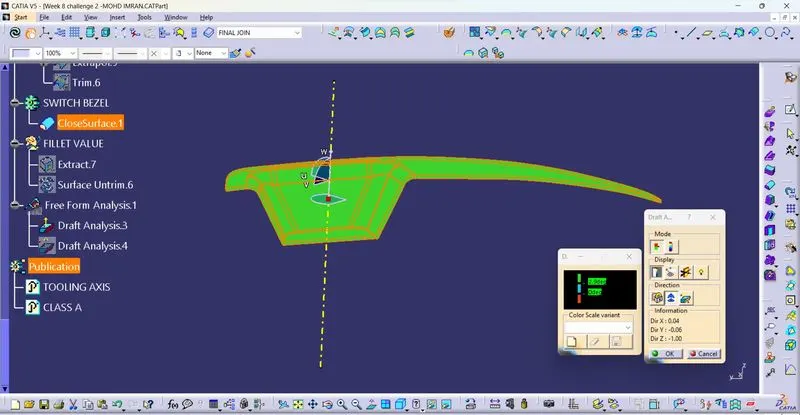
Screenshot of Draft analysis for Class A Surface and Final Plastic Component
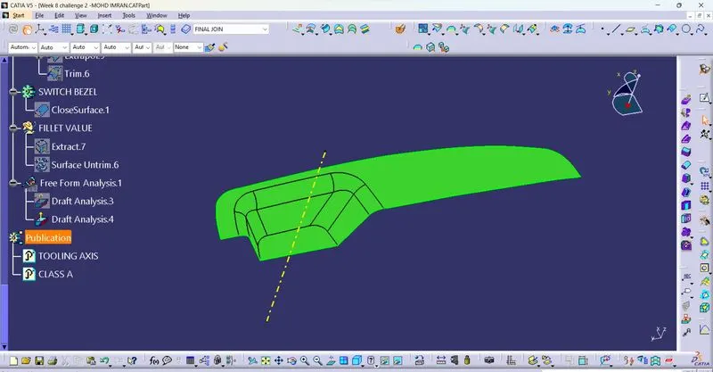
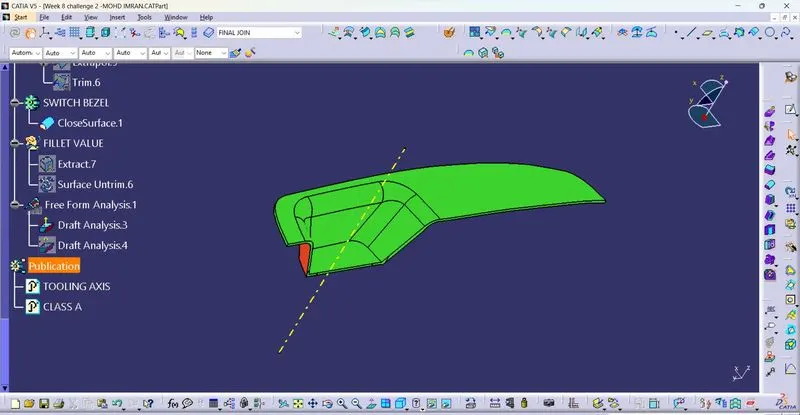
Isometric view
Front view
Back view
Left view
Right view
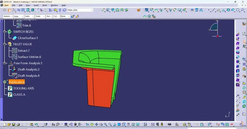
Top view
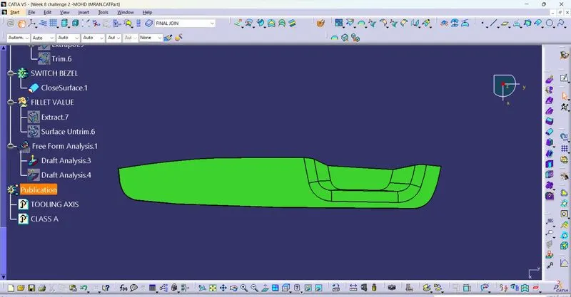
Bottom view