Radar Mast & Final Assembly of Yacht
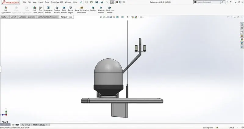
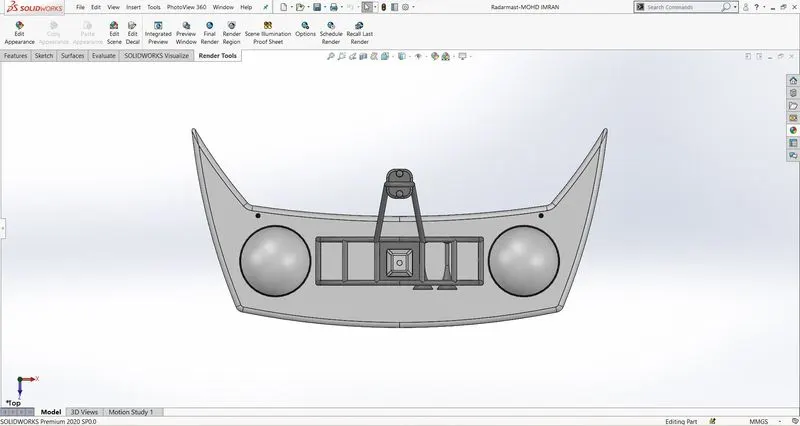
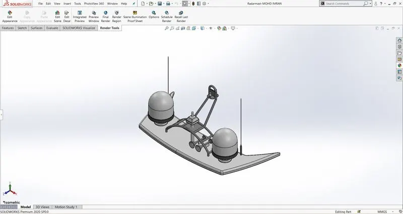
Radarmast
Feature tree images
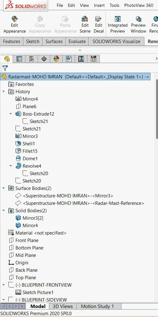
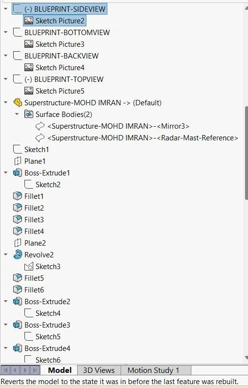
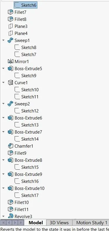
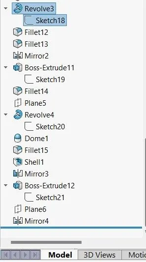
View orientation images
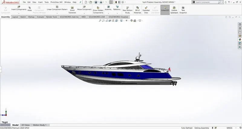
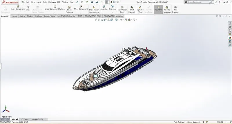
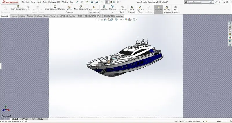
Assembly
Feature tree images
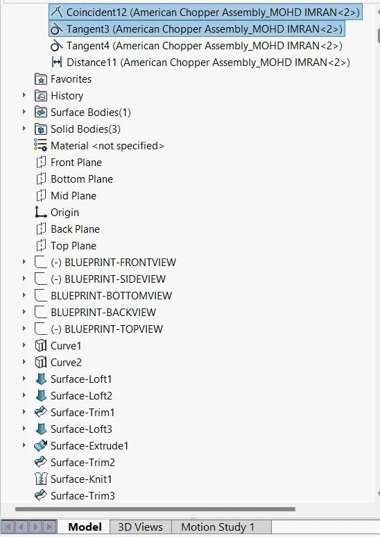
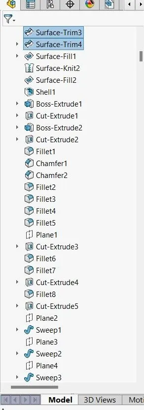
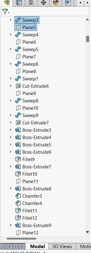
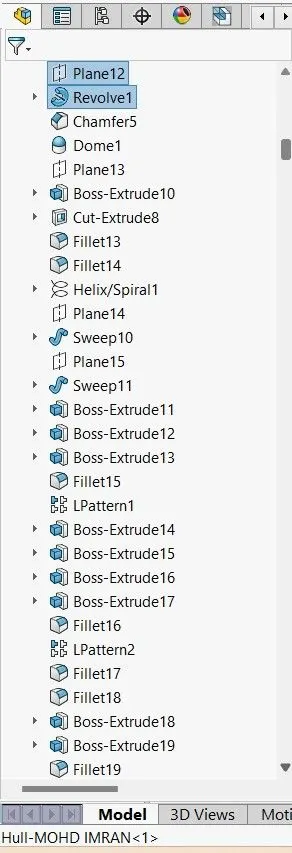
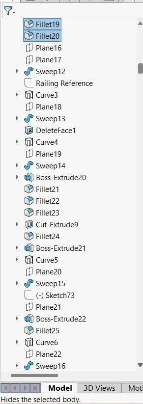
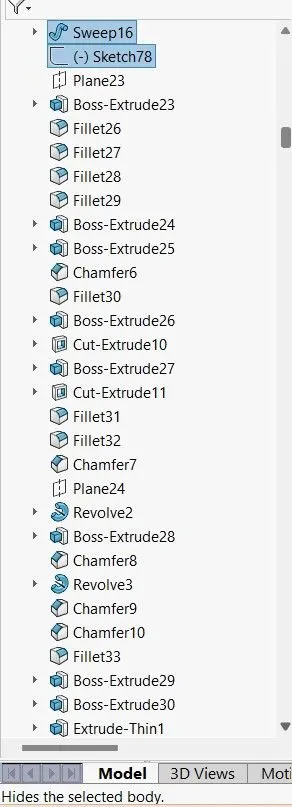
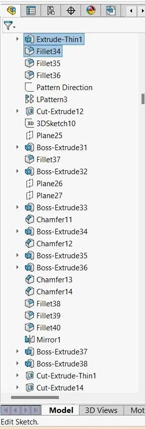
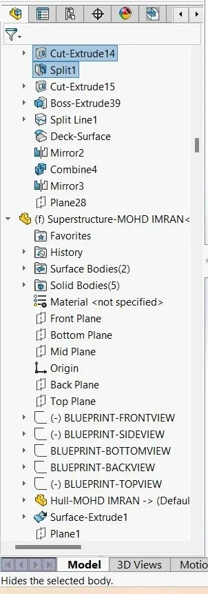
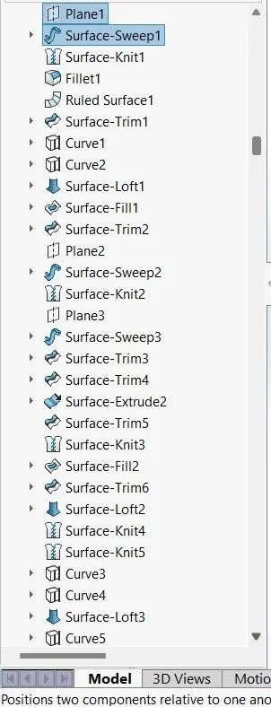
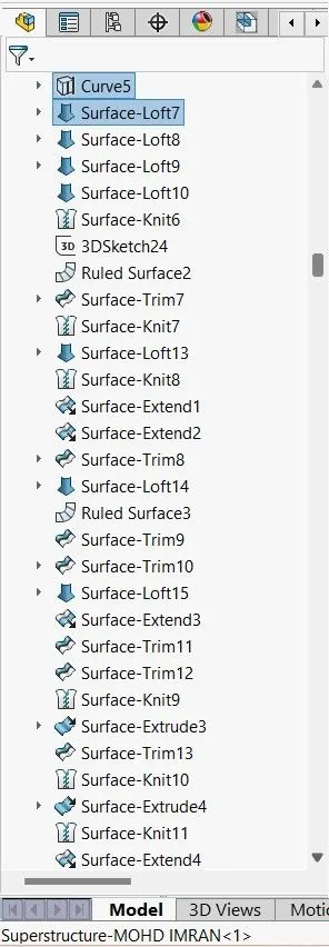
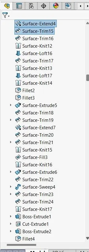
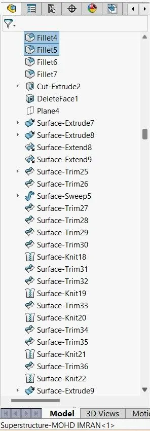
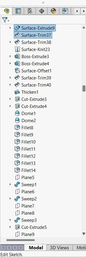
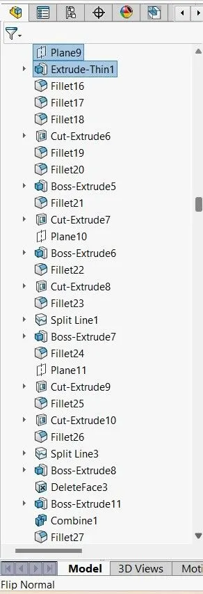
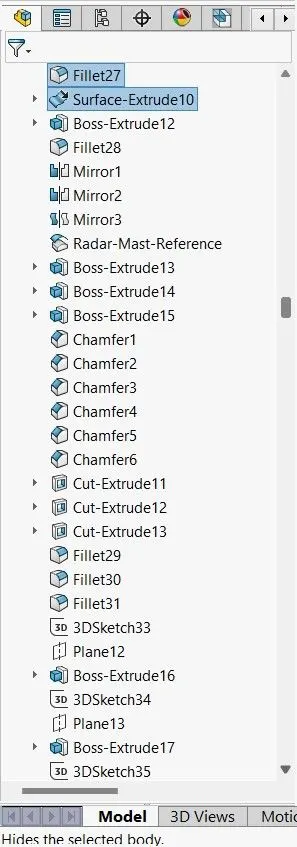
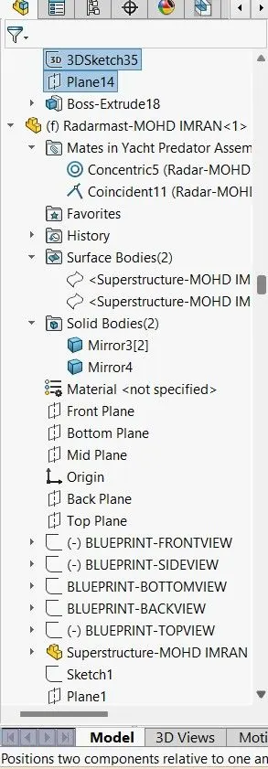
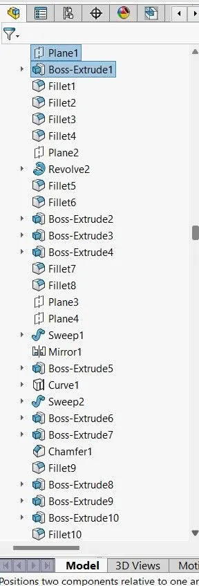
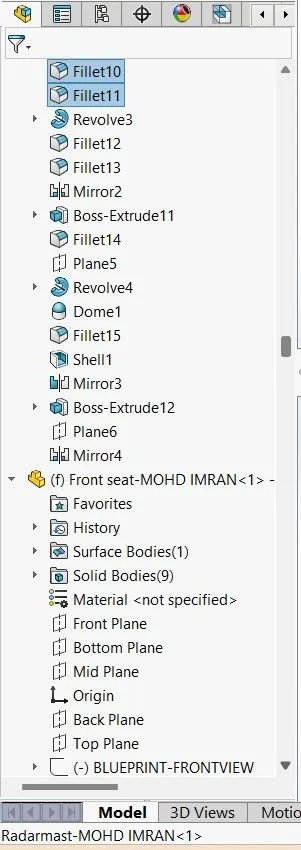
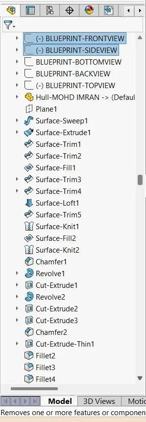
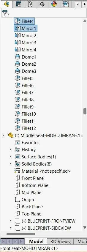
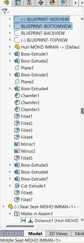
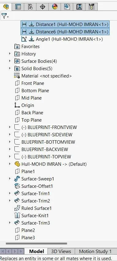
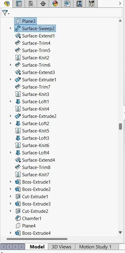
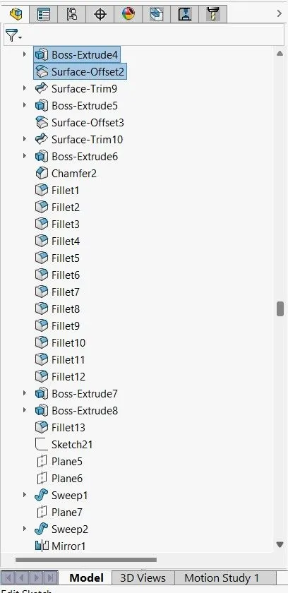
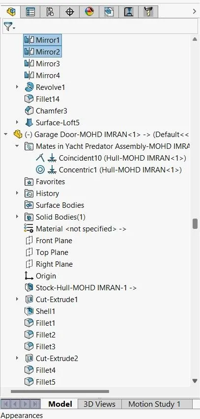
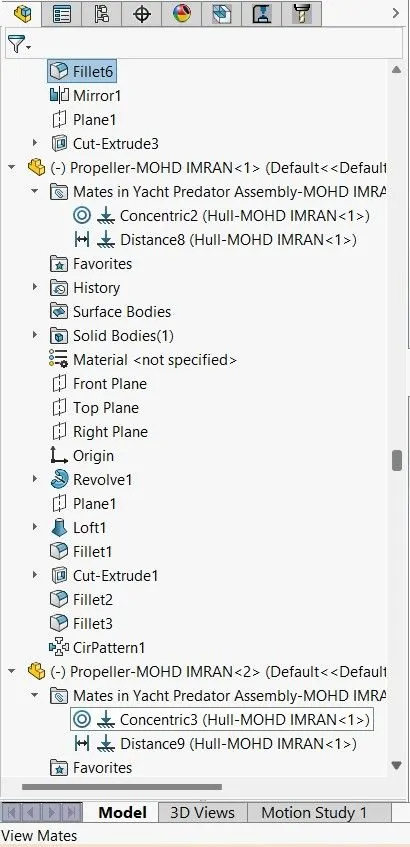
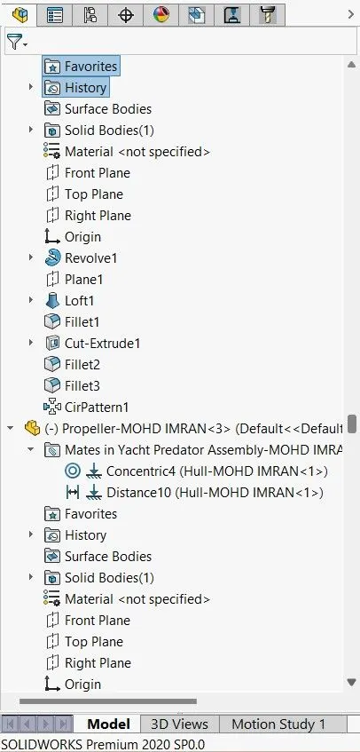
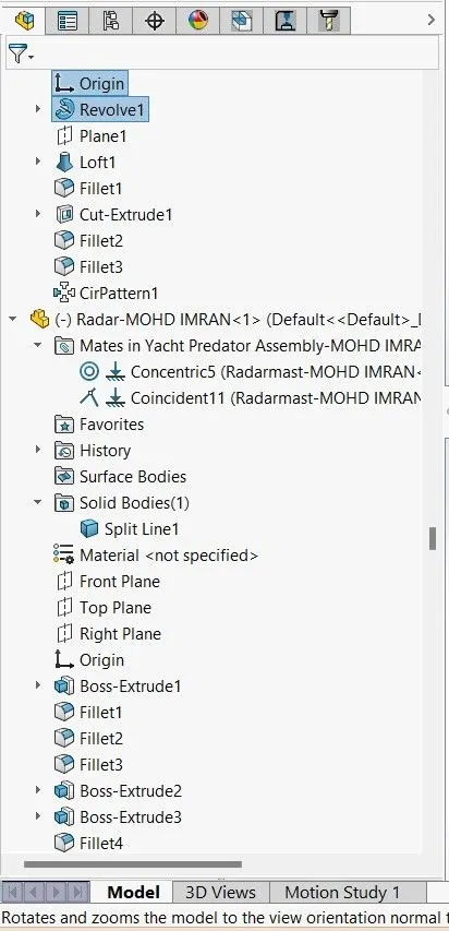
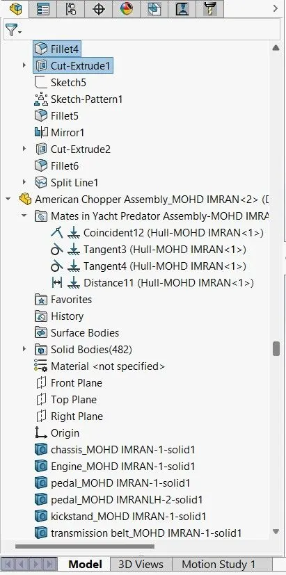
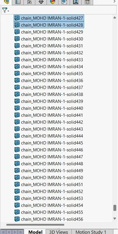
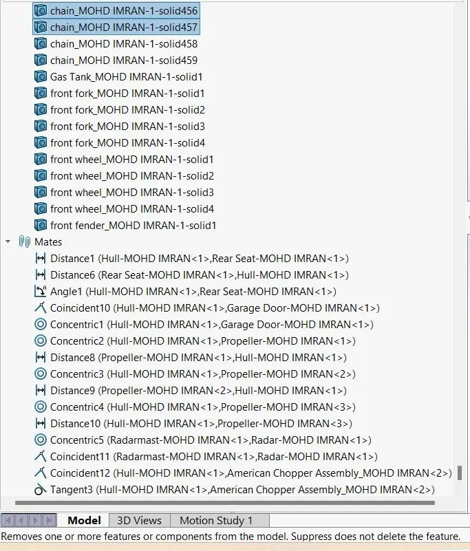
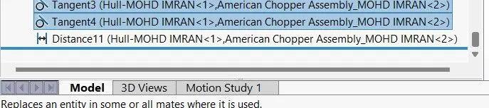
View orientation images
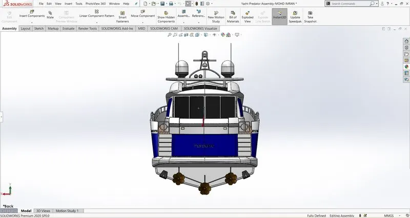
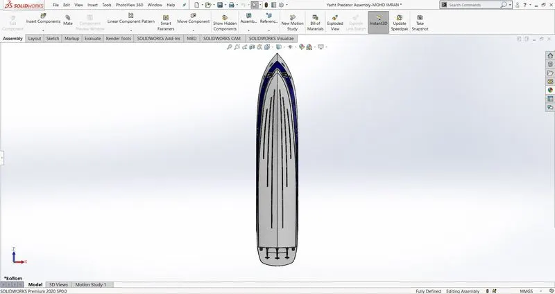
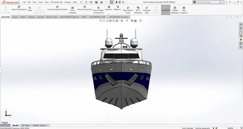
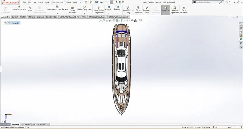
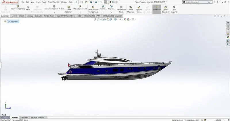
Report
TITLE OF THE PROJECT
Design and surface modeling, Assembly and Rendering of Sunseeker Predator Yacht using Solidworks.
OBJECTIVE
- The objective of this project is used to create a model of different parts of the Predator Yacht using Solidworks.
- To learn complex surfacing features within SOLIDWORKS.
- To learn SOLIDWORKS software as a design tool in an industrial approach.
- To assemble the different parts modeled for the Yacht.
- To be able to design an industrial product while keeping the design intent.
- To be industry ready for the role of Mechanical Design Engineer.
- To create a Photorealistic model of the chopper and Render the model using Solidworks Photoview 360 or Solidworks visualize.
INTRODUCTION
In this project I had to built a Sunseeker Predator Yacht 108.
Predator is a superyacht built in 2008 at the Dutch shipyard Royal De Vries Aalsmeer. The interior design of the Predator was done by Bannenberg Designs and the exterior by De Voogt Naval Architects.
Predator is a motor yacht with a length of 72.8m. The yacht's builder is Feadship from Netherlands who delivered superyacht Predator in 2008. The superyacht has a beam of 11.4m, a draft of 3.7m and a volume of 1,467 GT.
A yacht is a sailing or power vessel used for pleasure, cruising, or racing.There is no standard definition, though the term generally applies to vessels with a cabin intended for overnight use. To be termed a yacht, as opposed to a boat, such a pleasure vessel is likely to be at least 33 feet (10 m) in length and may have been judged to have good aesthetic qualities.
The Commercial Yacht Code classifies yachts 79 ft (24 m) and over as large. Such yachts typically require a hired crew and have higher construction standards. Further classifications for large yachts are: commercial—carrying no more than 12 passengers, private—solely for the pleasure of the owner and guests, or by flag, the country under which it is registered. A superyacht (sometimes megayacht) generally refers to any yacht (sail or power) longer than 131 ft (40 m).
Racing yachts are designed to emphasize performance over comfort. Charter yachts are run as a business for profit. As of 2020 there were more than 15,000 yachts of sufficient size to require a professional crew.
The history of pleasure boats begins with rowed craft in Pharaonic Egyptian times, and other vessels in the waters of Burma, India, Mindanao and Japan. It described 8th-century Anglo-Saxon royal pleg-scips (play ships) that featured ornamented bows and sterns and which had the capability of cooking on board.
Originally, all yachts were made of wood, using a wooden keel and ribs, clad with planks. These materials were supplanted with iron or steel in steam yachts.In the 1960s fiberglass became a prevalent material. These materials and others continue in use.Whereas yachts of 79 feet (24 m) and below may be constructed of fiberglass, larger yachts are more likely to be constructed of steel, aluminum or composite fiber-reinforced plastic.
Wood construction, using conventional planks over ribs continues. Hard-chined boats made with plywood is an infrequent technique, whereas yachts made with the WEST system—plies of wood strips, soaked in epoxy and applied over the boat frame—provide a durable, lightweight and robust hull.
Metal hulls from steel or aluminum offer the opportunity for welding components to a completely watertight hull. Both metals are vulnerable to damage due to electrolysis. Steel is easy to repair in boatyards around the world, whereas aluminum is a much lighter material.
Fiberglass construction is best suited for mass-produced yachts, using a mold and is therefore the most prevalent material. Fiberglass skins comprise plies of roving (glass fabric) and matting, soaked in resin for the hull. Decks typically have a core of balsa or PVC foam between layers of glass mat. Both elements of construction are vulnerable to intrusion of water and the development of blisters below the waterline.
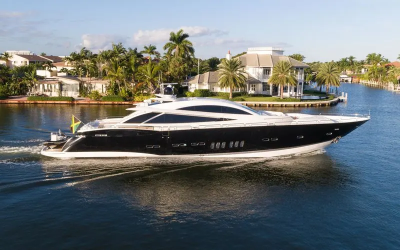
Image 1-Sunseeker Predator Yacht
DESIGN METHADOLOGY
Design and 3D Modelling
Some of the most important and frequently used feature in this project are described below.
Extruded surface
The EXTRUDE command creates a solid or surface that extends the shape of a curve. Open curves create surfaces and closed curves create solids or surfaces.
Lofted surface
Loft Surfaces are surfaces generated by multiple 3D Curves or existing edges creating a smooth tangency between the selected curves. Match Points are created between each selection denoting the orientation and path of the loft surface.
The loft feature is an important tool for (surface) modeling in SOLIDWORKS. The loft feature creates a shape by making transitions between multiple profiles and guide curves. This tool is very valuable for modeling complex surfaces. You can do some really cool stuff when you use this feature properly.
Fill surface
A Fill feature creates a surface patch over a closed boundary while matching position, tangency or curvature to surrounding geometry. Unlike the Loft feature, the fill surface can have as many boundary segments needed to construct a surface.
Trim surface
Primarily used to cut away material from a surface, and provides two modes: Standard and Mutual. In Standard mode, a single selection is defined as a Trim Tool, and target surfaces are trimmed accordingly.
Extend surface
An extended surface (also known as a combined conduction- convection system or a fin) is a solid within which heat transfer by. conduction is assumed to be one dimensional, while heat is also. transferred by convection (and/or radiation) from the surface in a. direction transverse to that of conduction.
Knit surface
The Knit Surface tool allows us to take two or more surfaces and combine them together into one surface. Most of the time it's going to be using the edges of those surfaces and think about almost like sewing them together to create one combined surface.
Boss extrude
Extrude tool is used to extend a sketched profile in one or two directions as either a thin feature or a solid feature. An extrude operation can either add material to a part (in a base or boss) or remove material from a part. Extruded Boss feature adds material to the part model.
Extruded cut
The Extrude Cut function removes material from solid bodies by extruding closed wireframe chains or planar surface geometry to the specified distance and subtracts the result from any intersecting solid or surface bodies.
Revolve
Revolves add or remove material by revolving one or more profiles around a centerline. You can create revolved boss/bases, revolved cuts, or revolved surfaces. The revolve feature can be a solid, a thin feature, or a surface.
Project curve
It allows the user to create curves by projecting the selected curves onto the face of the user-defined solid or surface geometry.
Rollback
To roll back to absorbed features:
- In the FeatureManager design tree, click to expand the absorbed features within the parent feature.
- Right-click an absorbed feature, and select Rollback. ...
- Click OK.
- Drag the rollback bar below the feature you selected in step 2.
Solid sweep
Sweep is an extrusion tool that allows you to extrude a profile such as a circle or a square or a complex shape along a sketched path.
Surface sweep
Sweep Surfaces are surfaces that are generated from a section curve positioned along a path. Various Sweep types are available to extend the sweep definition as follows: Sweep by Two Guide Curves is defined as moving and adjusting a section curve along two guide curves.
Reference geometry plane
Reference geometry is geometry that we create to be used as reference for the creation of new sketches and features. The types of reference geometry that exist are planes, axes, coordinate systems, and points.
Shell
The shell tool hollows out a part, leaves open the faces you select, and creates thin-walled features on the remaining faces. If you do not select any face on the model, you can shell a solid part, creating a closed, hollow model. You can also shell a model using multiple thicknesses.
Fillet
To create a fillet: Click Fillet (Features toolbar) or Insert > Features > Fillet/Round. Set the Property Manager options. For constant radius fillets only, you can use the Fillet Xpert to add or modify fillets and to manage fillet corners.
Chamfer
The chamfer tool creates a beveled feature on selected edges, faces, or a vertex. To create a chamfer: Click Chamfer (Features toolbar) or Insert > Features > Chamfer. Under Chamfer Parameters, select an item and set parameters.
Solid loft
Loft creates a feature by making transitions between profiles. A loft can be a base, boss, cut, or surface. You create a loft using two or more profiles. Only the first, last, or first and last profiles can be points. All sketch entities, including guide curves and profiles, can be contained in a single 3D sketch.
Circular pattern
To create circular sketch patterns: In an open sketch, click Circular Sketch Pattern (Sketch toolbar) or Tools > Sketch Tools > Circular Pattern. In the PropertyManager, under Entities to Pattern, select the sketch entities to pattern .
A circular pattern is an radial arrayof objects around a. Center point in a sketch. Axis in a part or assembly. Bolt pattern on automobile wheel would be an example
Appearance
To add an appearance, select the desired appearance in the appearance tab of the Task Manager. Left drag onto the model and hover over what you would like to apply the appearance to. Select Face, Feature, Body, Part or Assembly from the selection bar. You can also double-click on appearance to apply it to the part.
Dome
To create a dome: Click Dome on the Features toolbar, or click Insert > Features > Dome. You can create one or more dome features simultaneously on the same model.
Linear pattern
You can use linear patterns to create multiple instances of one or more features that you can space uniformly along one or two linear paths. Seed feature. Linear pattern - two directions.
Delete face
To delete faces from bodies:
- Click Delete Face on the Surfaces toolbar, or Insert > Face > Delete. The Delete Face Property Manager appears.
- In the graphics area, click the faces you want to delete. The names of the faces appear under Faces to delete .
- Under Options, click Delete.
- Click OK .
Mirror
Mirroring a Feature. Mirroring a feature is a little different. Features in SOLIDWORKS require a plane to be mirrored. To create a plane, I will highlight two faces in my sketch, then select Reference Geometry Plane. SOLIDWORKS will automatically add a MidPlane between these two faces
With the SOLIDWORKS part you want to mirror open, create a configuration and give it a name. In this instance, we will call it LH (Left Hand). Within that configuration, select the Mirror option from the Command Manager.
Method 1: Mirrored Version, Same Part
- Features to Mirror.
- Faces to Mirror.
- Bodies to Mirror.
Surface offset
The Offset Surface tool creates a new surface body from an existing set of faces. The faces may be solid or surface faces. To create an offset surface: Click Offset Surface (Surfaces toolbar) or Insert > Surface > Offset.
To create offset surfaces:
- Click Offset Surface (Surfaces toolbar) or Insert > Surface > Offset.
- In the Property Manager: Select surfaces or faces in the graphics area for Surface or Faces to Offset . Set a value for Offset Distance. You can create an offset surface with a distance of zero.
- Click OK .
Ruled surface
The Ruled Surface command creates surfaces that extend out in a specified direction from selected edges.
Split line
First up is the Split Line command. This command is generally useful when we need to create additional faces on a model without altering the geometry. To create a split line, we can either use a sketch, plane, or another solid body in the vicinity.
Follow below steps to learn how Split Line command works:
- Create a sketch of the graphic or break, normal to the model faces you want to split. ...
- Select the sketch, and then activate the Split Line command from the Curves drop-down in the Features Command Manager.
- Continue creating Split Line features as needed.
Sketch driven pattern
Using sketch points within a sketch, you can specify a feature pattern. The seed feature propagates throughout the pattern to each point in the sketch. You can use sketch driven patterns for holes or other feature instances.
To build a sketch driven pattern:
- Open a sketch on the face of a part.
- Create a seed feature on the model.
- Click Point or Tools > Sketch Entity > Point , and add multiple sketch points to represent the pattern you want to create, based on the seed feature.
- Close the sketch.
Copy surface
Follow below steps to learn how Copy a Surface
- Start by copying the surfaces of parts of the object.
- CTRL Select all object parts or face.
- Then go to Insert > Surface > Offset and select it.
- The Offset Surface dialog box will appear on the left. ...
- Change the Offset distance to 0.0in.
- Click the green checkmark. ...
- Save your part.
Description
Explained all the part given below which are the part of the assembly and also mentioned features which are used in assembly in Solidworks designing.
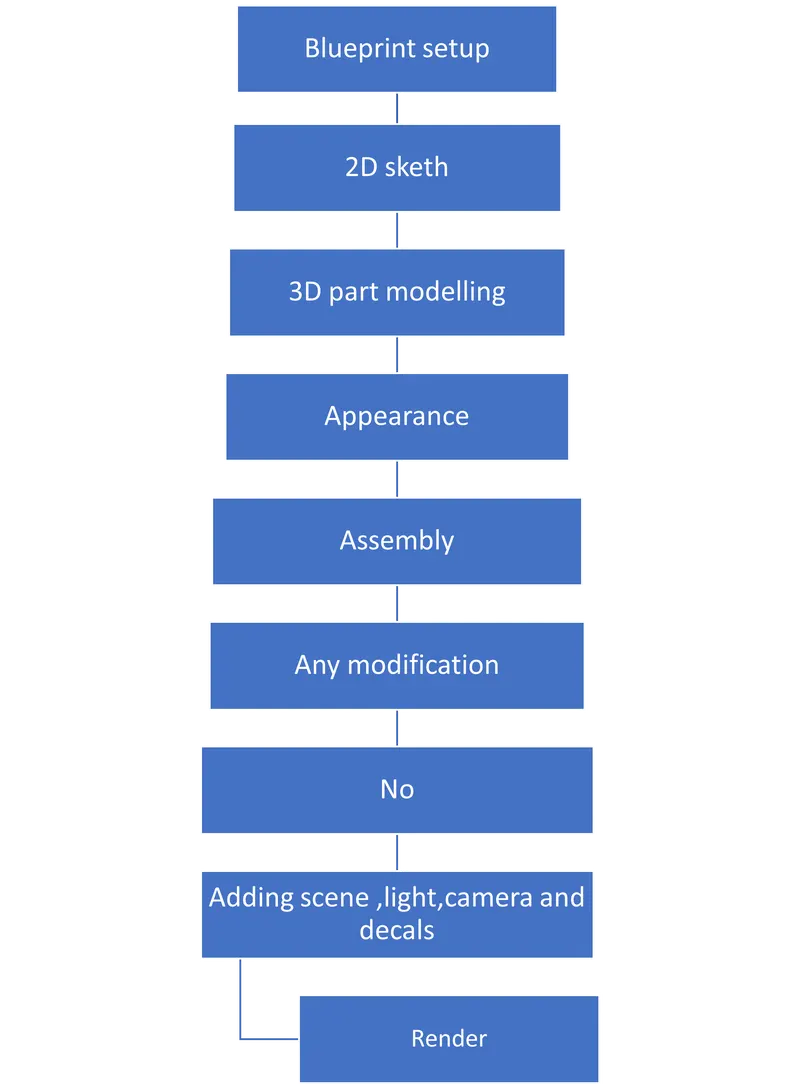
Blueprint setup
Blueprint setup is bunch of views setup and this setup is placed in proper dimension.We modelled maximum of yacht part with the help of Blueprint setup .This blueprint setup helps in modelling of 2d sketch and ease the modelling of yacht part and this setup is also helps in assembly because of its reference the maximum part of the yacht is automatically sets in assembly. So, it is very important to set all the blueprint properly with dimensions. If there is any small error in this setup it will lead to big problem in successive designing.
Part design
Propeller
A propeller (colloquially often called a screw if on a ship or an airscrew if on an aircraft) is a device with a rotating hub and radiating blades that are set at a pitch to form a helical spiral which, when rotated, exerts linear thrust upon a working fluid such as water or air.Propellers are used to pump fluid through a pipe or duct, or to create thrust to propel a boat through water or an aircraft through air. The blades are specially shaped so that their rotational motion through the fluid causes a pressure difference between the two surfaces of the blade by Bernoulli's principle which exerts force on the fluid.Most marine propellers are screw propellers with helical blades rotating on a propeller shaft with an approximately horizontal axis.
Although there was much experimentation with screw propulsion before the 1830s, few of these inventions were pursued to the testing stage, and those that were proved unsatisfactory for one reason or another.
In 1835, two inventors in Britain, John Ericsson and Francis Pettit Smith, began working separately on the problem. Smith was first to take out a screw propeller patent on 31 May, while Ericsson, a gifted Swedish engineer then working in Britain, filed his patent six weeks later.Smith quickly built a small model boat to test his invention, which was demonstrated first on a pond at his Hendon farm, and later at the Royal Adelaide Gallery of Practical Science in London, where it was seen by the Secretary of the Navy, Sir William Barrow. Having secured the patronage of a London banker named Wright, Smith then built a 30-foot (9.1 m), 6-horsepower (4.5 kW) canal boat of six tons burthen called Francis Smith, which was fitted with a wooden propeller of his own design and demonstrated on the Paddington Canal from November 1836 to September 1837. By a fortuitous accident, the wooden propeller of two turns was damaged during a voyage in February 1837, and to Smith's surprise the broken propeller, which now consisted of only a single turn, doubled the boat's previous speed, from about four miles an hour to eight.Smith would subsequently file a revised patent in keeping with this accidental discovery.
In the meantime, Ericsson built a 45-foot (14 m) screw-propelled steamboat, Francis B. Ogden in 1837, and demonstrated his boat on the River Thames to senior members of the British Admiralty, including Surveyor of the Navy Sir William Symonds. In spite of the boat achieving a speed of 10 miles an hour, comparable with that of existing paddle steamers, Symonds and his entourage were unimpressed. The Admiralty maintained the view that screw propulsion would be ineffective in ocean-going service, while Symonds himself believed that screw propelled ships could not be steered efficiently.Following this rejection, Ericsson built a second, larger screw-propelled boat, Robert F. Stockton, and had her sailed in 1839 to the United States, where he was soon to gain fame as the designer of the U.S. Navy's first screw-propelled warship, USS Princeton.
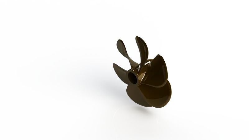
Tools used
Sketch tools
- Line
- Spline
- 3 Point corner rectangle
- Circle
Features
- Revolve
- Reference geometry plane
- Solid loft
- Fillet
- Extruded cut
- Circular pattern
- Appearance
Hull
A hull is the watertight body of a ship, boat, or flying boat. The hull may open at the top (such as a dinghy), or it may be fully or partially covered with a deck.
There is a wide variety of hull types that are chosen for suitability for different usages, the hull shape being dependent upon the needs of the design. Shapes range from a nearly perfect box in the case of scow barges to a needle-sharp surface of revolution in the case of a racing multihull sailboat. The shape is chosen to strike a balance between cost, hydrostatic considerations (accommodation, load carrying, and stability), hydrodynamics (speed, power requirements, and motion and behavior in a seaway) and special considerations for the ship's role, such as the rounded bow of an icebreaker or the flat bottom of a landing craft. Perhaps the earliest proper hulls were built by the Ancient Egyptians, who by 3000 BC knew how to assemble wooden planks into a hull.
Hulls come in many varieties and can have composite shape, (e.g., a fine entry forward and inverted bell shape aft), but are grouped primarily as follows:
Chined and hard-chined. Examples are the flat-bottom (chined), v-bottom, and multi-chine hull (several gentler hard chines, still not smooth). These types have at least one pronounced knuckle throughout all or most of their length.
Moulded, round bilged or soft-chined. These hull shapes all have smooth curves. Examples are the round bilge, semi-round bilge, and s-bottom hull.
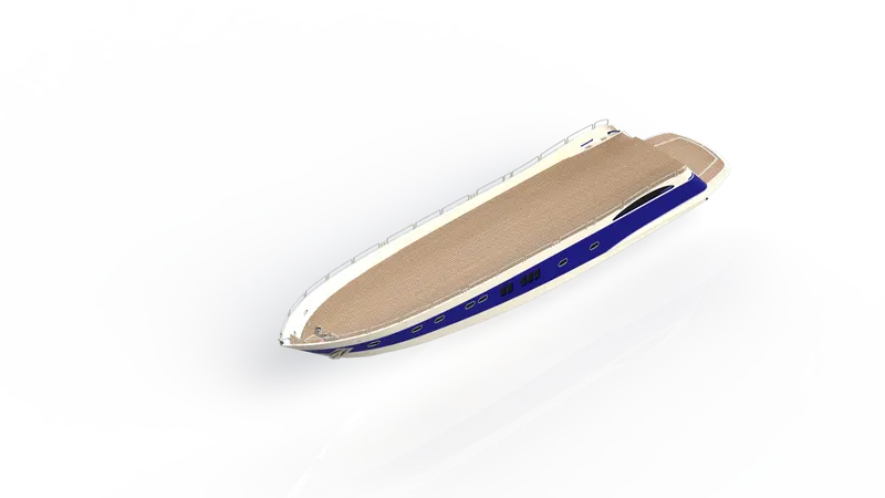
Tools used
Insert blueprint setup and save as Hull
Sketch tools
- Line
- Spline
- Centreline
- Trim
- Linear pattern
- Straight slot
- Copy
- Circle
- Convert entities
- 3d sketch
- Offset entities
- Corner rectangle
- 3 point centre rectangle
- Sketch fillet
- Ellipse
- Mirror
Features
- Projected curve
- Surface loft
- Surface trim
- Surface extrude
- Knit surface
- Surface fill
- Shell
- Boss extrude
- Extruded cut
- Fillet
- Chamfer
- Reference geometry plane
- Solid sweep
- Revolve
- Dome
- Helix/spiral
- Linear pattern
- Delete face
- Thin extrude
- Mirror
- Thin cut extrude
- Split body
- Split line
- Appearance
- Copy surface
Radar
Radar is a detection system that uses radio waves to determine the distance (ranging), angle, and radial velocity of objects relative to the site. It can be used to detect aircraft, ships, spacecraft, guided missiles, motor vehicles, weather formations, and terrain. A radar system consists of a transmitter producing electromagnetic waves in the radio or microwaves domain, a transmitting antenna, a receiving antenna (often the same antenna is used for transmitting and receiving) and a receiver and processor to determine properties of the objects. Radio waves (pulsed or continuous) from the transmitter reflect off the objects and return to the receiver, giving information about the objects' locations and speeds.
Radar was developed secretly for military use by several countries in the period before and during World War II. A key development was the cavity magnetron in the United Kingdom, which allowed the creation of relatively small systems with sub-meter resolution. The term RADAR was coined in 1940 by the United States Navy as an acronym for radio detection and ranging.The term radar has since entered English and other languages as a common noun, losing all capitalization.
The modern uses of radar are highly diverse, including air and terrestrial traffic control, radar astronomy, air-defense systems, anti-missile systems, marine radars to locate landmarks and other ships, aircraft anti-collision systems, ocean surveillance systems, outer space surveillance and rendezvous systems, meteorological precipitation monitoring, altimetry and flight control systems, guided missile target locating systems, self-driving cars, and ground-penetrating radar for geological observations. High tech radar systems are associated with digital signal processing, machine learning and are capable of extracting useful information from very high noise levels.
Other systems similar to radar make use of other parts of the electromagnetic spectrum. One example is lidar, which uses predominantly infrared light from lasers rather than radio waves. With the emergence of driver-less vehicles, radar is expected to assist the automated platform to monitor its environment, thus preventing unwanted incidents.
The information provided by radar includes the bearing and range (and therefore position) of the object from the radar scanner. It is thus used in many different fields where the need for such
positioning is crucial. The first use of radar was for military purposes: to locate air, ground and sea targets. This evolved in the civilian field into applications for aircraft, ships, and automobiles.
In aviation, aircraft can be equipped with radar devices that warn of aircraft or other obstacles in or approaching their path, display weather information, and give accurate altitude readings. The first commercial device fitted to aircraft was a 1938 Bell Lab unit on some United Air Lines aircraft.Aircraft can land in fog at airports equipped with radar-assisted ground-controlled approach systems in which the plane's position is observed on precision approach radar screens by operators who thereby give radio landing instructions to the pilot, maintaining the aircraft on a defined approach path to the runway. Military fighter aircraft are usually fitted with air-to-air targeting radars, to detect and target enemy aircraft. In addition, larger specialized military aircraft carry powerful airborne radars to observe air traffic over a wide region and direct fighter aircraft towards targets.
Marine radars are used to measure the bearing and distance of ships to prevent collision with other ships, to navigate, and to fix their position at sea when within range of shore or other fixed references such as islands, buoys, and lightships. In port or in harbour, vessel traffic service radar systems are used to monitor and regulate ship movements in busy waters.
Meteorologists use radar to monitor precipitation and wind. It has become the primary tool for short-term weather forecasting and watching for severe weather such as thunderstorms, tornadoes, winter storms, precipitation types, etc. Geologists use specialized ground-penetrating radars to map the composition of Earth's crust. Police forces use radar guns to monitor vehicle speeds on the roads. Smaller radar systems are used to detect human movement. Examples are breathing pattern detection for sleep monitoring and hand and finger gesture detection for computer interaction.Automatic door opening, light activation and intruder sensing are also common.
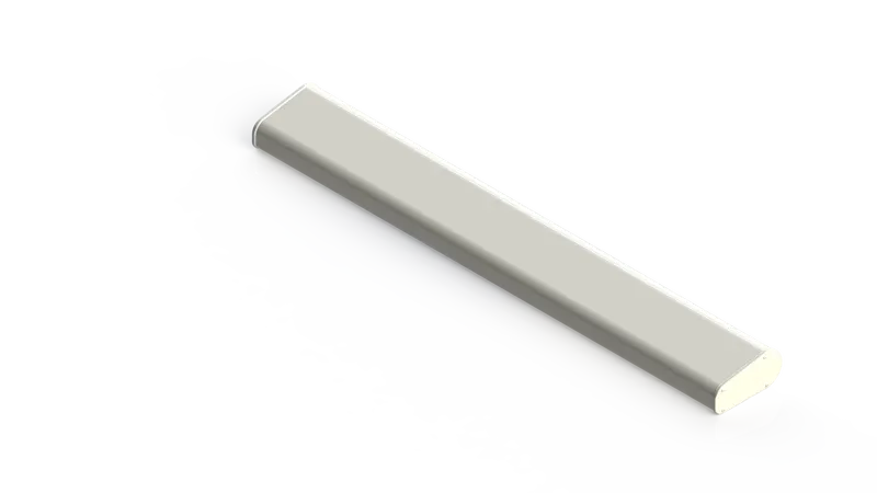
Tools used
Sketch tools
- Line
- Offset entities
- Circle
- Polygon
- Point
- Centreline
- Sketch text
Features
- Boss extrude
- Fillet
- Extruded cut
- Sketch driven pattern
- Mirror
- Split line
- Appearance
Front seat
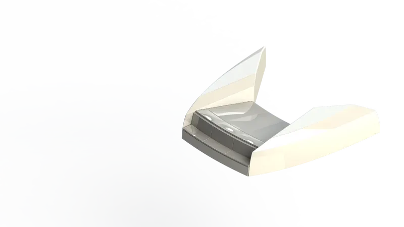
Designing of front seat started with creating the curves with reference to blueprint. The major features used during designing of front seat were surface loft, surface trim, surface knit, cut extrude. A dome was also used to create mattress like appearance on the seat. The mattress was provided with light gray color whereas the other seat surface with white color.
Tools used
Insert blueprint setup and save as Front seat.
Import the deck surface of the hull as interface surface.
Go to insert>part
Uncheck all the option except the surface body option.
Sketch tools
- Spline
- Line
- Convert entities
- Trim
- Centreline
- Corner rectangle
- Offset entities
Features
- Reference geometry plane
- Surface sweep
- Surface extrude
- Surface trim
- Fill surface
- Surface loft
- Knit surface
- Chamfer
- Revolve
- Extrude cut
- Fillet
- Mirror
- Dome
- Appearance
Middle seat
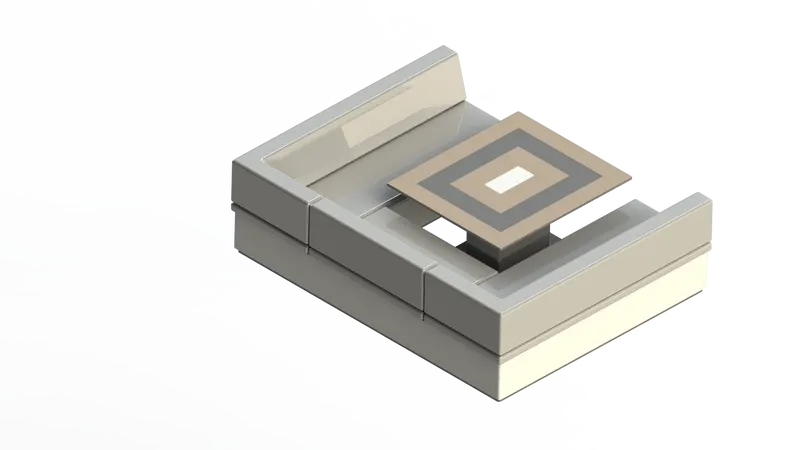
Middle seat is located behind the superstructure. It was created with reference of blueprint on hull surface. One table was also created with the middle seat. The major feature used during designing the middle seat were boss extrude, chamfer, fillet.
Tools used
Insert blueprint setup and save as Middle seat.
Import the deck surface of the hull as interface surface.
Go to insert>part
Uncheck all the option except the surface body option.
Sketch tools
- Line
- Offset entities
- Trim
- Corner rectangle
Features
- Boss extrude
- Reference geometry plane
- Chamfer
- Fillet
- Mirror
- Cut extrude
- Appearance
Rear seat
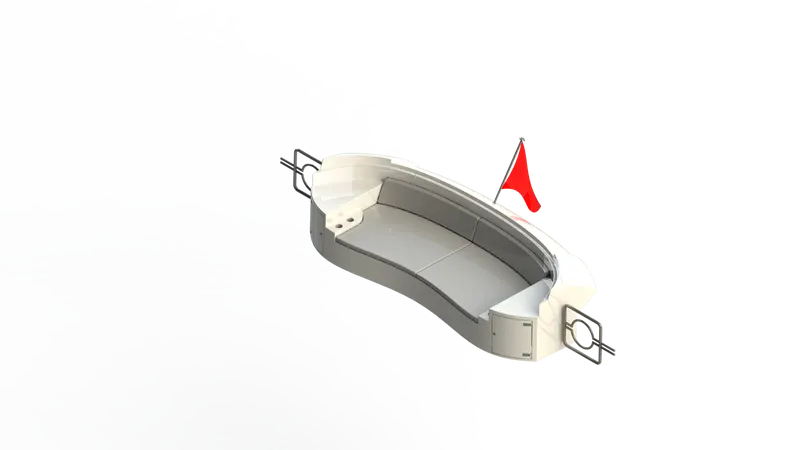
Rear seat was most complex among the three seats that’s why it was first crated as closed surface body and then converted into solid body. While designing rear seat I first create closed surface body of half seat by using surface tools like sweep, trim, knit and loft. Seat was first designed half and then it was mirrored to get the full seat. Major surface tool used for designing rear seat were sweep, loft, trim, knit, extend.
Tools used
Insert blueprint setup and save as Rear seat.
Import the deck surface of the hull as interface surface.
Go to insert>part
Uncheck all the option except the surface body option.
Sketch tools
- Line
- Spline
- Convert entities
- 3d sketch
- Trim
- Corner rectangle
- Offset entities
- Circle
- Centreline
- Sketch fillet
Features
- Reference geometry plane
- Surface sweep
- Surface offset
- Surface trim
- Ruled surface
- Surface knit
- Surface extrude
- Surface loft
- Surface extend
- Boss extrude
- Cut extrude
- Chamfer
- Fillet
- Solid sweep
- Mirror
- Revolve
- Appearance
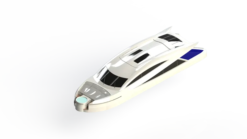
Superstructure
A superstructure is an upward extension of an existing structure above a baseline. This term is applied to various kinds of physical structures such as buildings, bridges, or ships.
On water craft, the superstructure consists of the parts of the ship or a boat, including sailboats, fishing boats, passenger ships, and submarines, that project above her main deck. This does not usually include its masts or any armament turrets. Note that in modern times, turrets do not always carry naval artillery, but they can also carry missile launchers and/or antisubmarine warfare weapons.
The size of a watercraft's superstructure can have many implications in the performance of ships and boats, since these structures can alter their structural rigidity, their displacements, and/or stability. These can be detrimental to any vessel's performance if they are taken into consideration incorrectly.
The height and the weight of superstructure on board a ship or a boat also affects the amount of freeboard that such a vessel requires along its sides, down to her waterline. In broad terms, the more and heavier superstructure that a ship possesses (as a fraction of her length), the less the freeboard that is needed.
Tools used
Insert blueprint setup and save as Superstructure.
Import the deck surface of the hull as interface surface.
Go to insert>part
Uncheck all the option except the surface body option.
Sketch tools
- Line
- Spline
- 3d sketch
- Convert entities
- Trim
- Offset entities
- Centreline
- Split entities
- Circle
- Corner rectangle
- Extend
- 3 point corner rectangle
- Centerpoint arc
Features
- Surface extrude
- Reference geometry plane
- Surface sweep
- Surface knit
- Fillet
- Ruled surface
- Surface trim
- Projected curve
- Surface loft
- Surface fill
- Extend surface
- Delete face
- Fillet
- Boss extrude
- Cut extrude
- Surface offset
- Thicken surface
- Dome
- Solid sweep
- Split line
- Mirror
- Copy surface
- Chamfer
- Appearance
Garage door
A garage door is a large door on a garage that opens either manually or by an electric motor (a garage door opener). Garage doors are frequently large enough to accommodate automobiles and other vehicles.
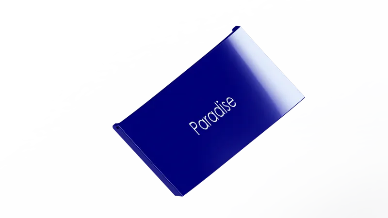
As like the other parts of the yacht garage door is also designed half and then mirrored about mid plane. Garage door was created out of the splited block out of hull. Holes with the help of cut extrude were created at upper side for pins, through which garage door will connect to the hull and open and close. Blue color was given as appearance to it.
Tools used
Open the garage door.sldprt
Sketch tools
- Line
- Circle
- Centreline
- Sketch text
Features
- Extruded cut
- Shell
- Fillet
- Mirror
- Reference plane geometry
- Appearance
Radarmast
A mast is a pole that rises vertically from a ship and supports the sails. Really big sailboats have more than one mast. A mast is also another name for flagpole. The mast has an important job — to support the sails, which allows the wind to propel the ship.
Marine radars are X band or S band radars on ships, used to detect other ships and land obstacles, to provide bearing and distance for collision avoidance and navigation at sea.
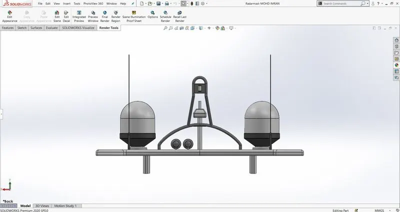
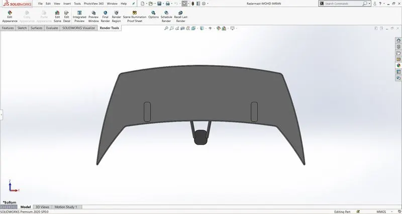
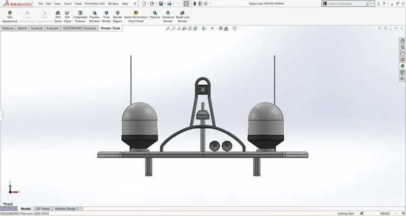
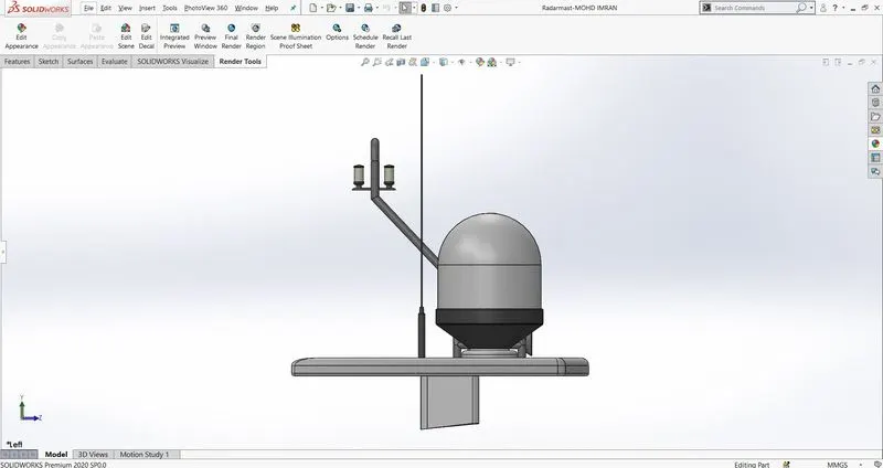
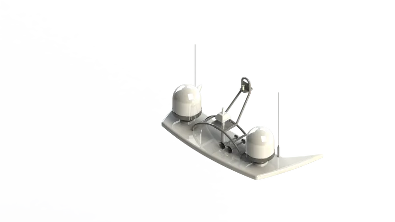
Radar mast is an multi body part consisting of antenna, navigation light, fog horn and radar scanner. Boss extrude, sweep, revolve, fillet and mirror were the main features while crating this part. White color is given as appearance to most of the parts.
The mast of a sailing vessel is a tall spar, or arrangement of spars, erected more or less vertically on the centre-line of a ship or boat. Its purposes include carrying sails, spars, and derricks, and giving necessary height to a navigation light, look-out position, signal yard, control position, radio aerial or signal lamp.Large ships have several masts, with the size and configuration depending on the style of ship. Nearly all sailing masts are guyed.
Until the mid-19th century, all vessels' masts were made of wood formed from a single or several pieces of timber which typically consisted of the trunk of a conifer tree. From the 16th century, vessels were often built of a size requiring masts taller and thicker than could be made from single tree trunks. On these larger vessels, to achieve the required height, the masts were built from up to four sections (also called masts). From lowest to highest, these were called: lower, top, topgallant, and royal masts.Giving the lower sections sufficient thickness necessitated building them up from separate pieces of wood. Such a section was known as a made mast, as opposed to sections formed from single pieces of timber, which were known as pole masts.
Tools used
Insert blueprint setup and save as Radarmast.
Import the deck surface of the hull as interface surface.
Go to insert>part
Uncheck all the option except the surface body option.
Sketch tools
- Line
- Spline
- 3 point arc
- Circle
- Centerline
- Center point arc
- Trim
- Corner rectangle
- Straight slot
Features
- Reference geometry plane
- Boss extrude
- Fillet
- Revolve
- Solid sweep
- Mirror
- Projected curve
- Chamfer
- Dome
- Shell
- Appearance
Assembly
After the design of all parts of Yacht successfully assemble all the parts in Solidworks.
For the assembly go to the menu bar and click on file
File ≥New≥Assembly
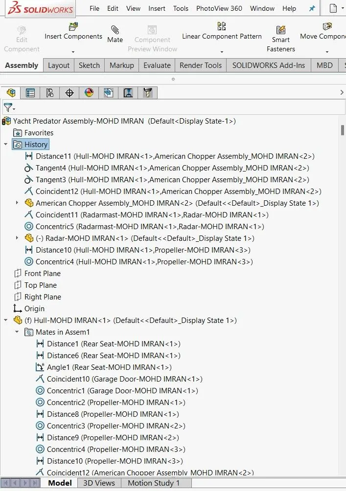
Then insert the parts in (part/assembly to insert) section after that apply appropriate mates and assemble all the parts.
Maximum of the part of the yacht assembled automatically because of hull of the deck surface reference.
Mates those are apply in assembly of American chopper bike are given below.
- Distance between face of the hull and face of the rear seat(0mm).
- Distance between vertex of the hull and vertex of the rear seat(50mm).
- Angle mate between mid plane of the hull and mid plane of the rear seat(0 deg).
- Coincident mate between mid plane of hull and right plane of the rear seat.
- 2 Concentric mate between face of hull and face of garage door.
- Distance mate between face of the propeller and face of the hull(0mm).
- Concentric mate between face of the propeller and face of the hull.
- Coincident mate between face of the radarmast and face of the hull.
Rendering
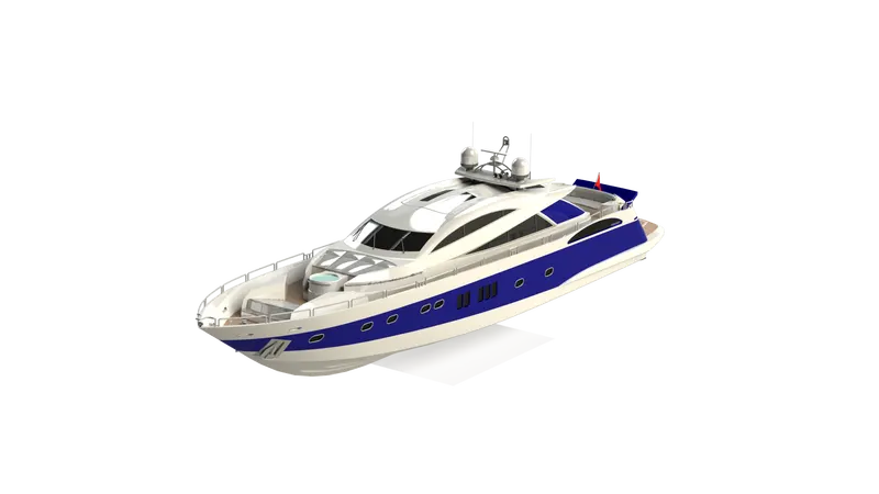
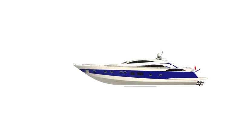
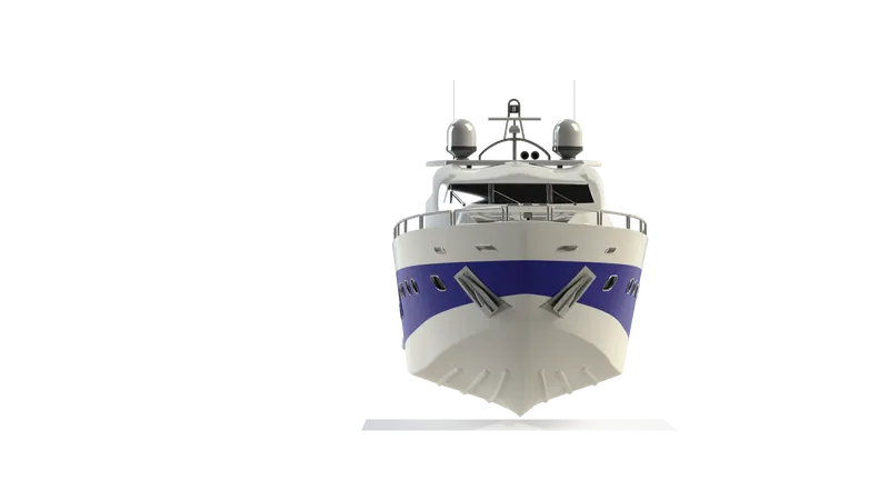
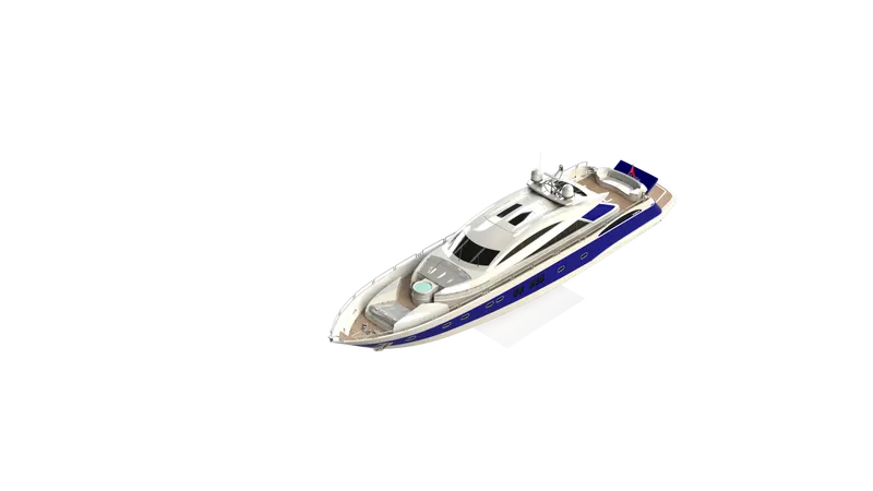
We have two rendering in Solidworks Photoview 360 and Solidworks visualize and rendering is successfully done by using Photoview 360 and Solidworks visualize.
PHOTOVIEW 360
For rendering in photoview 360 go to in menu bar and click on option icon then click add in and select photoview 360.
In photoview 360 we have many features in context menu bar for rendering and those are given below.
1-Edit appearance
Edits the appearance of entities in the model.When you edit an appearance assigned to a group of entities,the appearance updates for all entities.You can edit appearance properties such as texture mapping and colors.
2-Copy appearance
Copies the appearance of one entities so you can paste it onto another using the paste appearance tool.Use this tool to copy appearances instead of recreating them.
For copy appearances use ctrl+shift+c key.
3-Paste appearance
Paste the appearance that you copy from one entity to others in the model.Pasted appearances retain all the customizations made in the edit appearance property manager.Use the appearance target pallete to target the pasted appearance to an entity.
For paste appearance use ctrl+shift+v key.
4-Edit scene
Edit the scene applied to the document.
5-Edit decal
Applies a decal to faces in a model.
6-Integrated preview
Displays the photoview 360 preview inside the solidworks graphic area.
7-Preview window
8-Final render
9-Render region
Defines a graphics window region to render(either preview or final render)
10-Scene illumination proof sheet
11-Options
Edit the photoview 360 rendering options.
12-Schedule render
Use the Schedule Render dialog box to perform a rendering at a specified time and save it to a file.
13-Recall last render
Uses of features that are used in rendering of American chopper bike in Photoview 360
- Edit appearance
- Edit scenes
- Edit decals
- Preview window
- Option
- Final render
- Schedule render
- Camera setup
SOLIDWORKS VISUALIZE
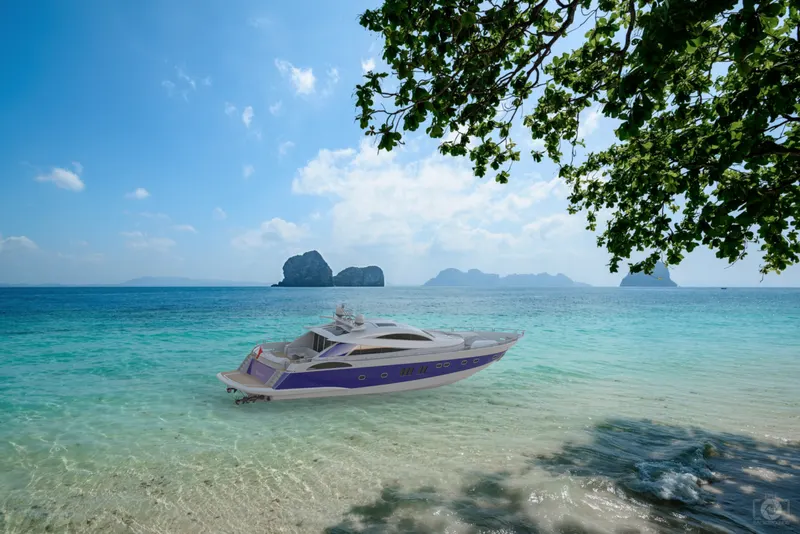
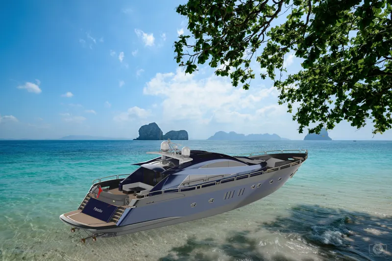
SOLIDWORKS Visualize allows you to leverage your 3D CAD data to create photo-quality content in the fastest and easiest way you can–from images to animations, interactive web content, and immersive Virtual Reality. Bring your products to life. SOLIDWORKS Visualize is the “camera” for your CAD data.
CONCLUSION
Successfully designed, assembled and rendered the Sunseeker predator 108 yacht. Learned to design the complex surfaces in solidworks. Also learned SOLIDWORKS software as a design tool in industrial manner. This project really helps me to enhance my designing skill and help me to become industry ready for the role of Mechanical Design Engineer. Overall, the project was successful.