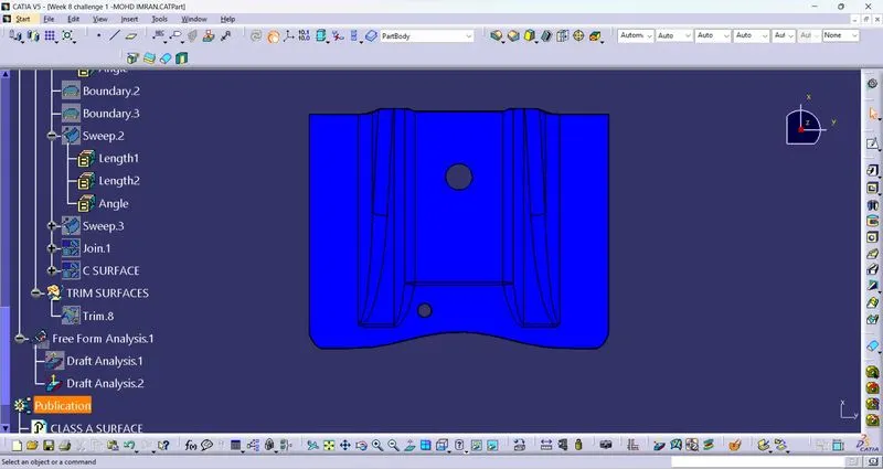
Week 8 - Challenge 1 - Base Bracket Design
TITLE OF THE PROJECT
Base Bracket Design
AIM
to Create the Base Bracket Plastic component through the given Class-A surface.Create a Tooling axis and Draft analysis on the model.
to Create the Base Bracket Plastic component through the given Class-A surface.Create a Tooling axis and Draft analysis on the model.
INTRODUCTION
In the BASE BRACKET DESIGN Create the Base Bracket Plastic component through the given Class-A surface. To begin with, the tooling axis for the given Class-A Surface should be created meeting the requirements of the draft angle and at the end perform the Draft analysis on the model.
NOTE:Thickness of Plastic Part - 2.5 mm
OBJECTIVE
- Creation of tooling axis.
- Draft analysis of Class A Surface.
- Creation of B Surface by given Class A Surface.
- Creation of C Surface.
- Creation of solid part by using closed surface.
TOOLING AXIS
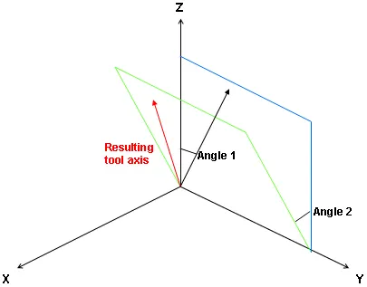
Tooling axis define as a
- Angle 1 about X, Angle 2 about Y: The tool axis is rotated an Angle 1 about the x-axis, then rotated an Angle 2 about the y-axis.
- Angle 1 about Z, Angle 2 about X: The tool axis is rotated an Angle 1 about the z-axis, then rotated an Angle 2 about the x-axis.
- Angle 1 about Y, Angle 2 about Z: The tool axis is rotated an Angle 1 about the y-axis, then rotated an Angle 2 about the z-axis.
Creation of point
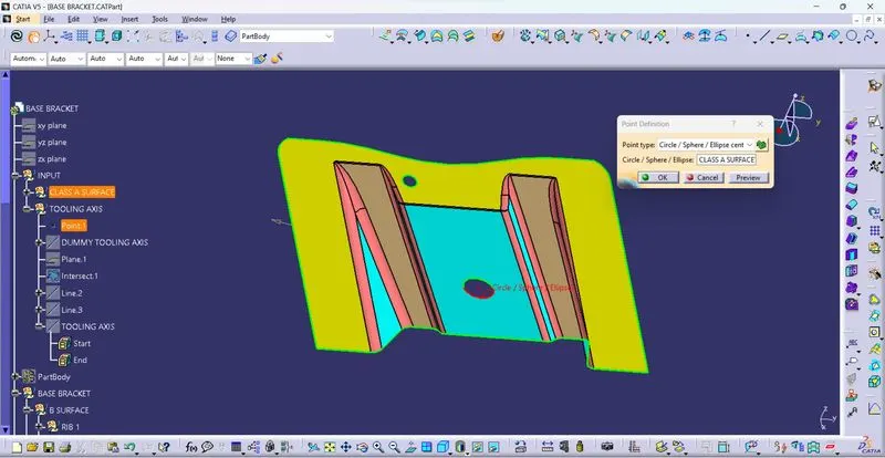
In this Base Bracket Design first thing is create a point in a centre of a circle which are located on a base surface .Name of the point is Point 1.
Why not in smaller circle?
Because the draft angle of the surfaces is covered by the bigger circle which are located onn the base surface.
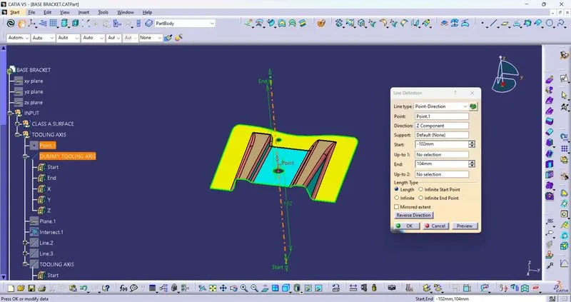
Creation of dummy tooling axis
Dummy tooling axis is created in the middle of the circle which are located on the base surface about Z direction.
Creation of plane
Create a Plane and give the the reference YZ Plane and point reference is point 1 which are created in the beginning in the centre of the circle.
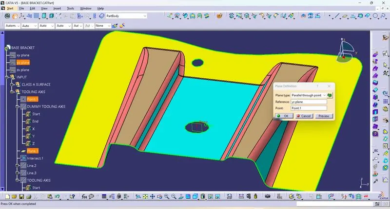
Creation of Intersection
Go to the Wireframe toolbar and click on the intersection then give the first element as Class A Surface and second element is pont 1.
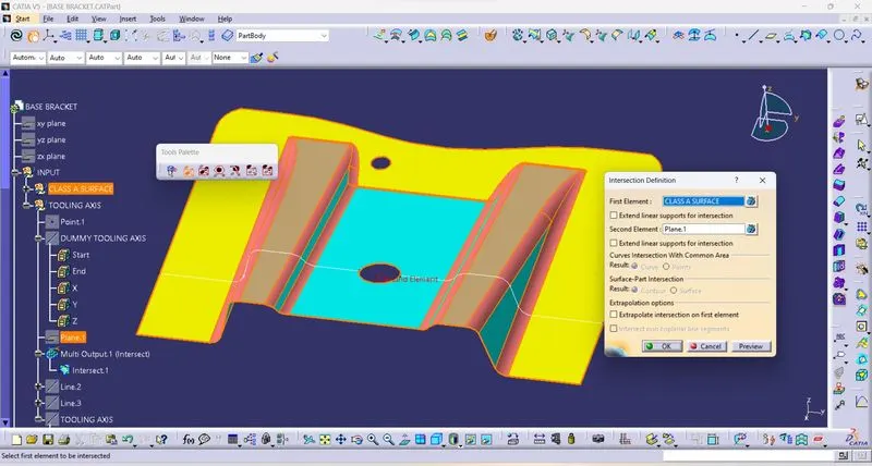
Create a Line 1
Create a line go to the Wireframe select the line and type is point to point,reference for point 1 select the lower vertex of the left side line that line is making a draft angle and reference for the point 2 select the upper vertex of the line.
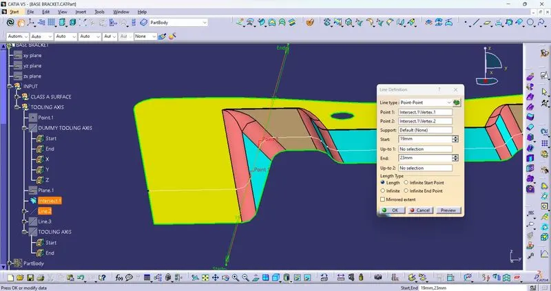
Create a Line 2
Create a line and go to the Wireframe select the line and type is point to point,reference for point 1 select the lower vertex of the right side line that line is making a draft angle and reference for the point 2 select the upper vertex of the line.
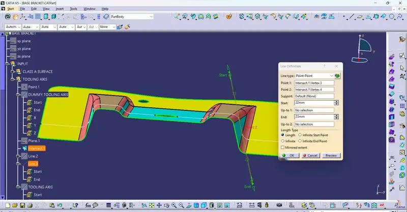
Creation of Tooling Axis Line
In the last go to the Wireframe select the line option and select the type of the line is Bisecting,reference for line1 and line 2 select the those are create by using intersection of the Class A Surface choose both of them for the reference of line line 1 and line 2 after that for the reference for the point select the point 1.
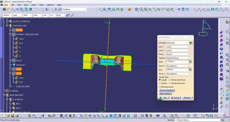
Now the Tooling Axis is successfully created.
DRAFT ANALYSIS
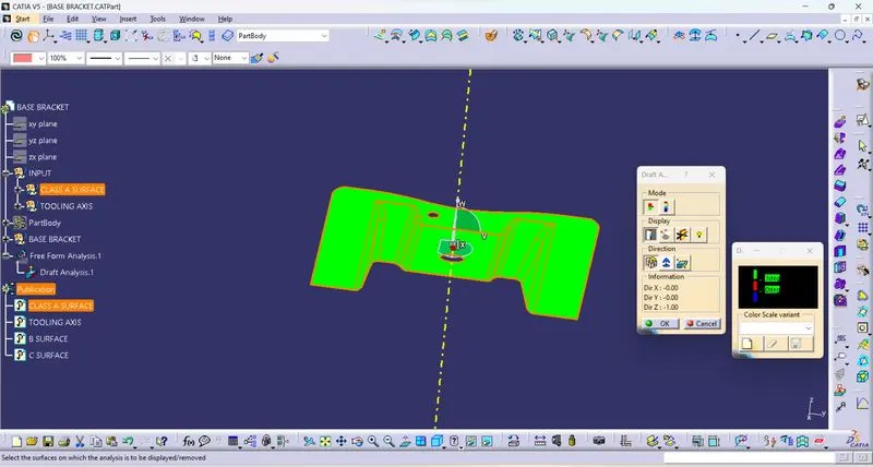
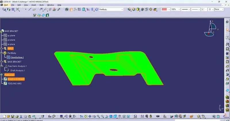
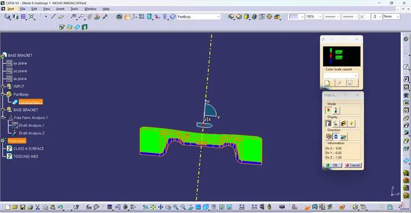
- Go to insert< analysis< feature draft analysis.
- Align the tooling axis with the compass.
- Click on the surface and see that the surface is within the permissible limit of the draft values.
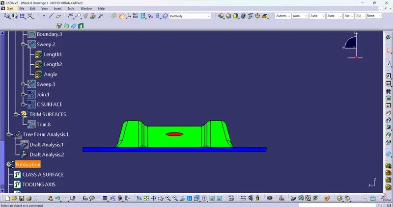
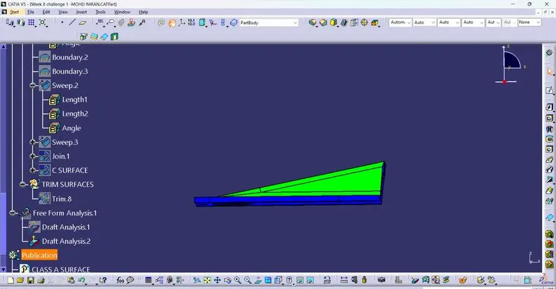
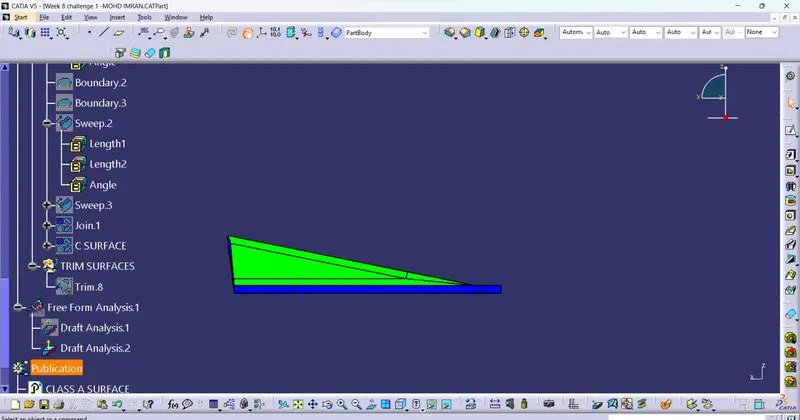
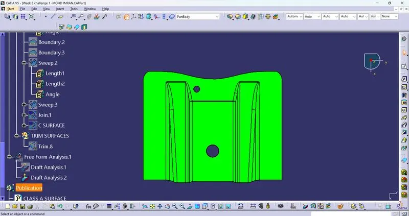
- The surface should be green and in the column proper value (3deg) should be inserted.
CREATION OF B SURFACE
In the creation of B Surface, we are going to devide Class A Surfaces into some geometric set and these geometric set is the children of the B Surface.
- Rib 1
- Rib 2
- Base Surface
- Final Trim
For Rib 1 and Rib 2
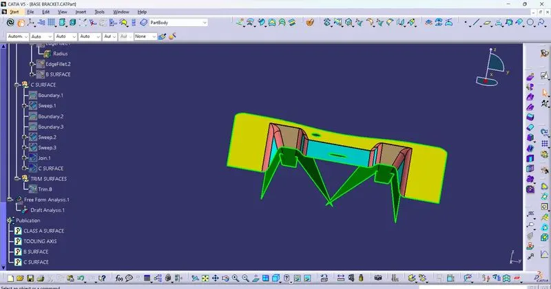
Extract the Rib 1 and Rib 2 surfaces one by one.
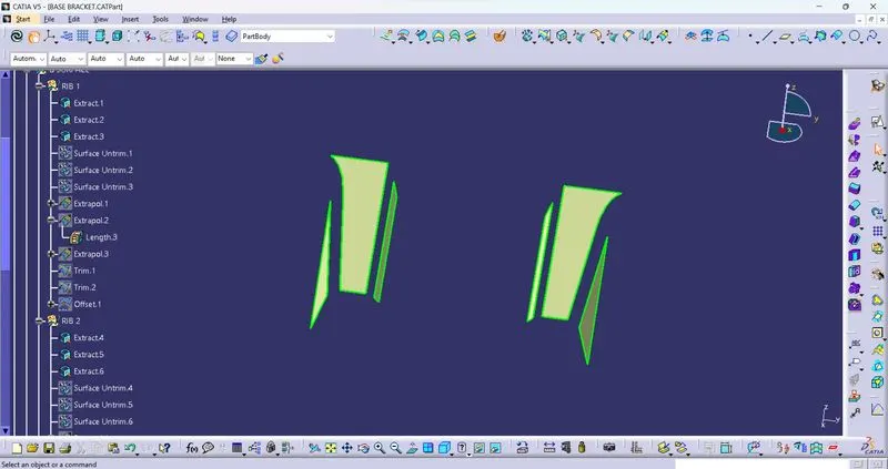
Untrim the all surfaces one by one.
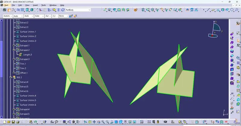
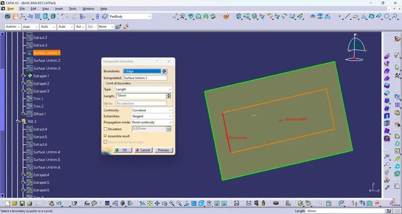
Extrapolate all the surface one by one.
For Extrapolate surface right click on the surface of any edges then go to propagation mode and select point continuity,in a continuity option select the curvature and extremeties is tangent.
For the extrapolate length is 10mm.
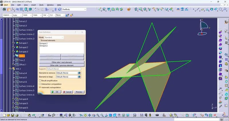
Trim the surfaces for Rib 1 and Rib 2.
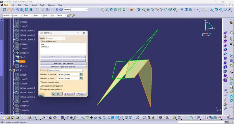
Offset both the rib 2.5mm in inner direction.
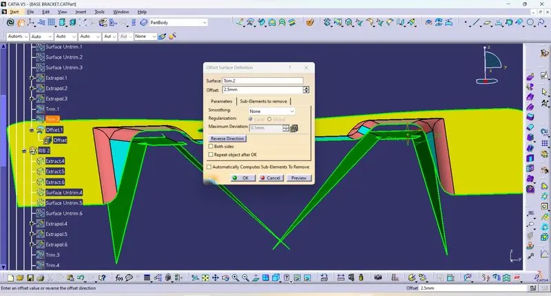
For Base Surface
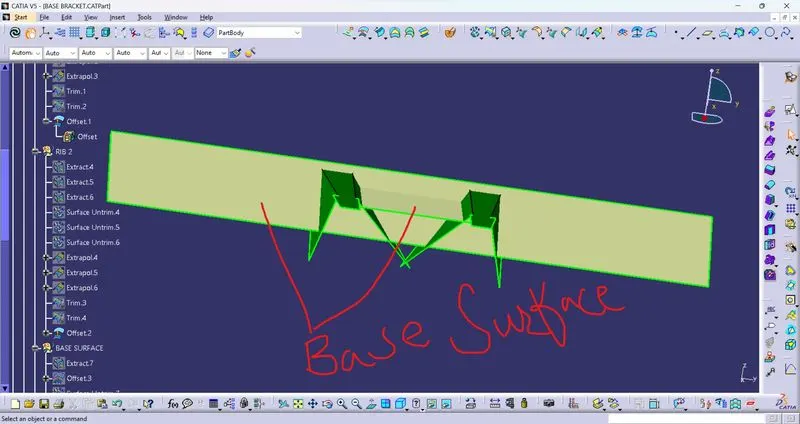
Extract the Base Surface
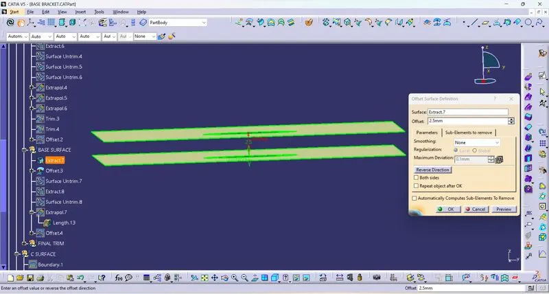
Offset the Base Surface 2.5mm in inner direction.
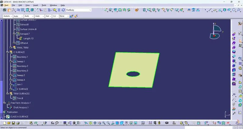
Untrim the Base surface.
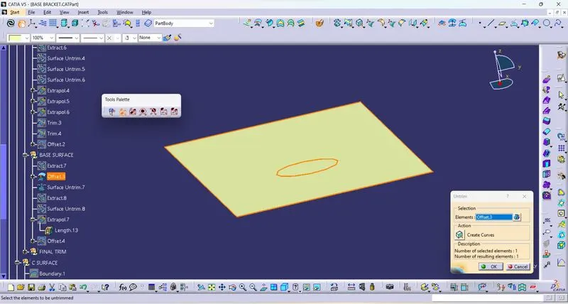
Extract the Lower Base Surface.
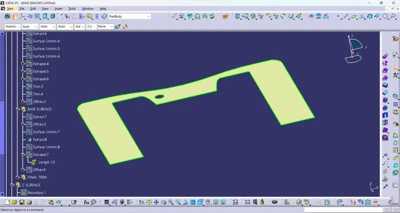
Untrim the Lower Base surface.
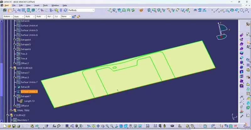
Extrapolate the Base Surface 10mm.
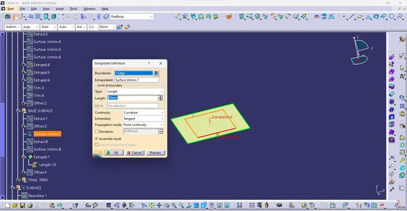
Offset the Lower Base Surface 2.5mm in inner direction.
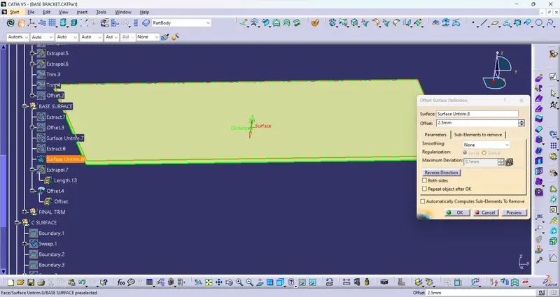
For Final Trim(B SURFACE)
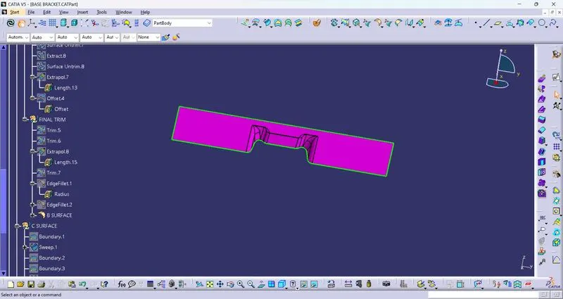
Trim Rib 1,Rib 2 and Base surface(upper and lower) with each other to get a result.
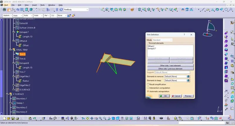
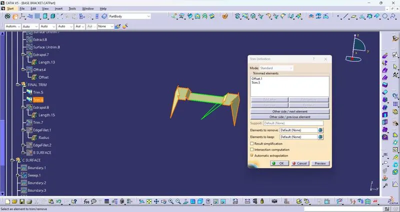
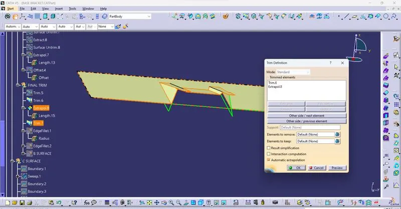
Fillet the edges of base bracket.
Formula for filleting= fillet value+thickness (if the surface is below).
For fillet =2.5+3=5.5mm
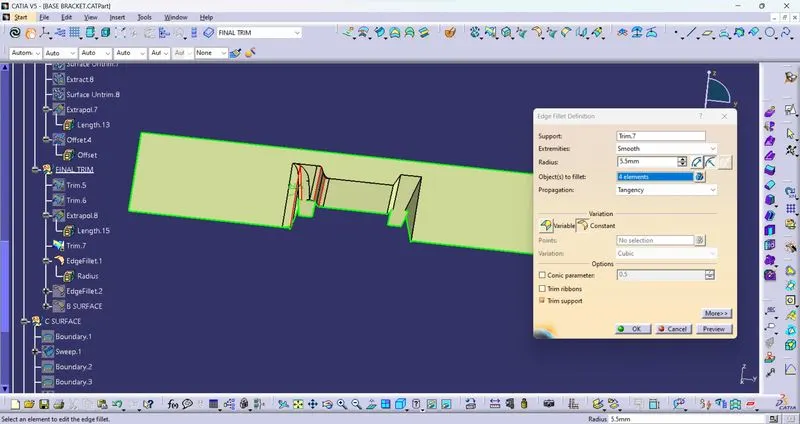
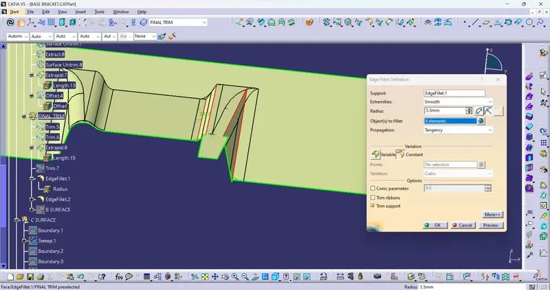
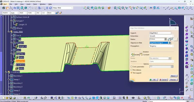
Result B Surface is created
CREATION OF C SURFACE
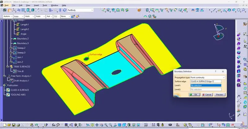
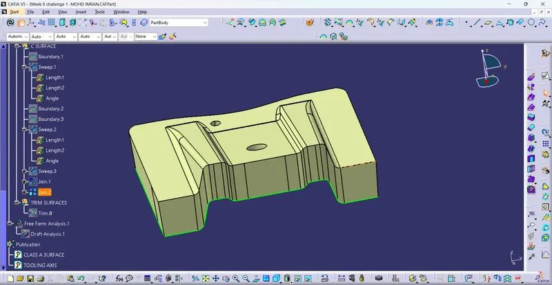
Extract the boundary of Class A.
Go to the Operation command in operation open the extract and select the BOUNDARY Command.
In Boundary definition Propagation type is point continuity and select the surface edge then click the right button of the mouse and select the any edge of the Class A Surface.
Then hit on OK button.
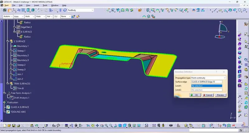
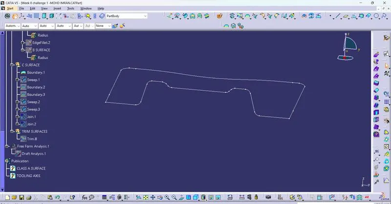
Sweep the boundary
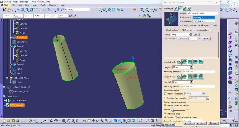
Go to Surface command and choose Sweep command and give the angle 3 degree.
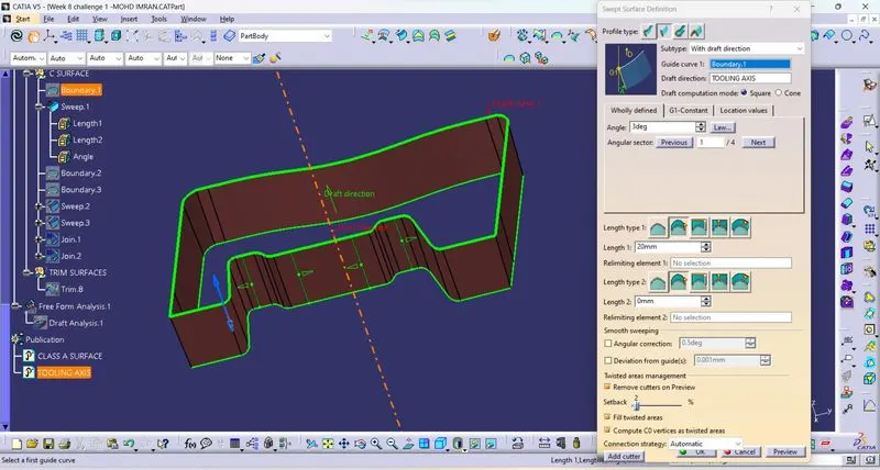
Extract the boundary of both the Circle.
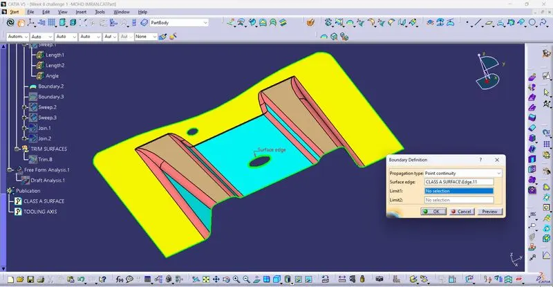
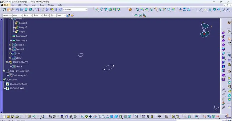
Sweep both boundary of circle and give an angle 3 degree.
Join all the surfaces together.
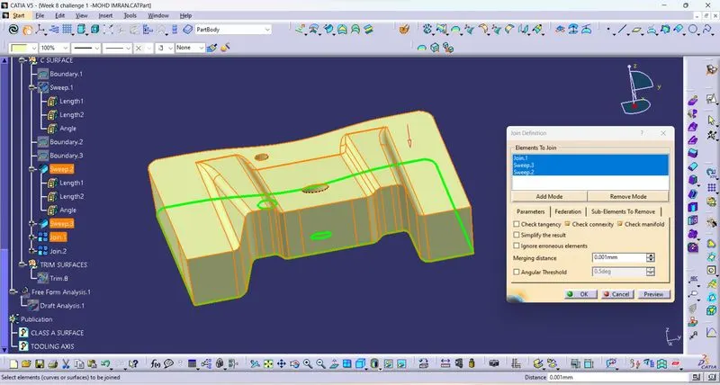
Result C Surface is created
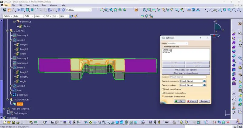
Creation of solid part by using closed surface.
Close the surface by trim command by using of B Surface and C Surface.
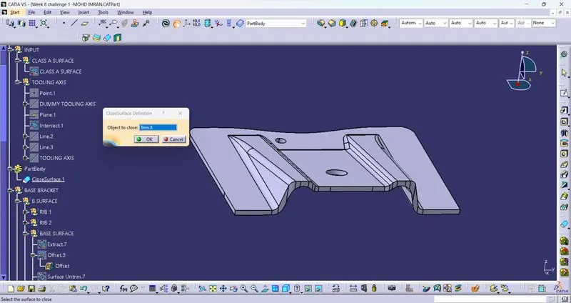
Open the Part Design Workbench.
Go to Start menu click on Mechanical Design and select Part Design.
After that go to surface based feature command and select the closed surface command.
By the use of closed surface command make a Solid body out of it.
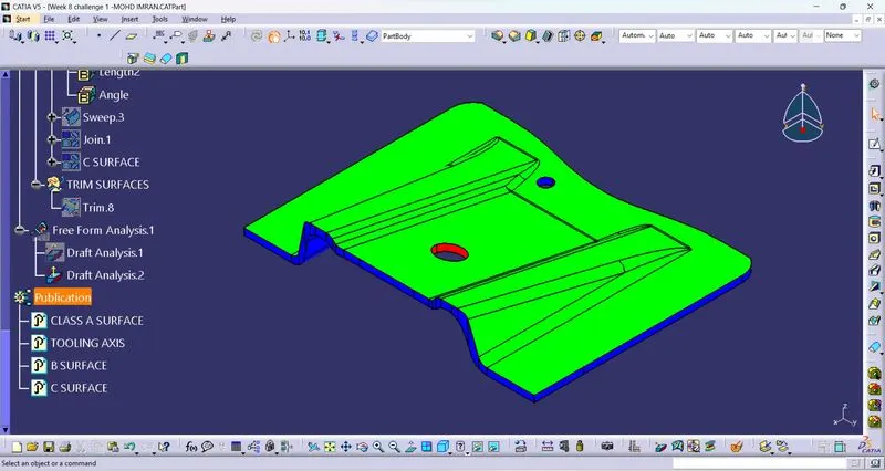
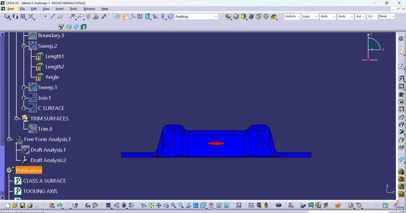
Screenshot of Draft analysis for Class A Surface and Final Plastic Component
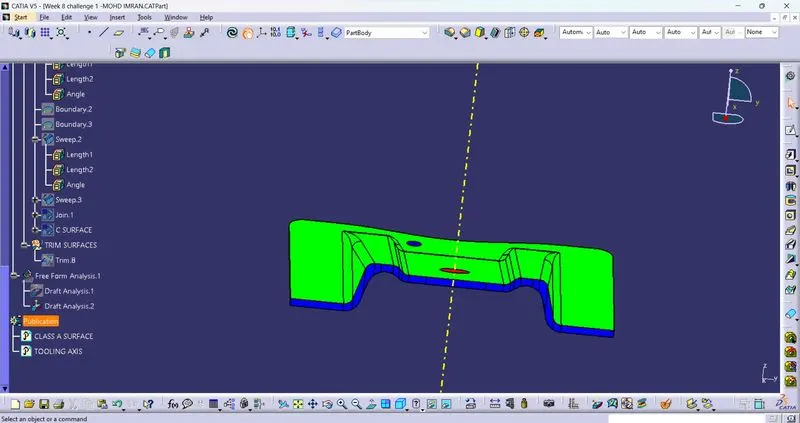
Isometric view
Front view
Back view
Left view
Right view
Top view
Bottom view