Photo Realistic Rendering
Modelling American chopper
Objective :-
To create the Model of a American chopper in Solidworks using the various types of sketches and the features tool form the solidworks. Also create photorealistic rendered image of American chopper.
Introduction :-
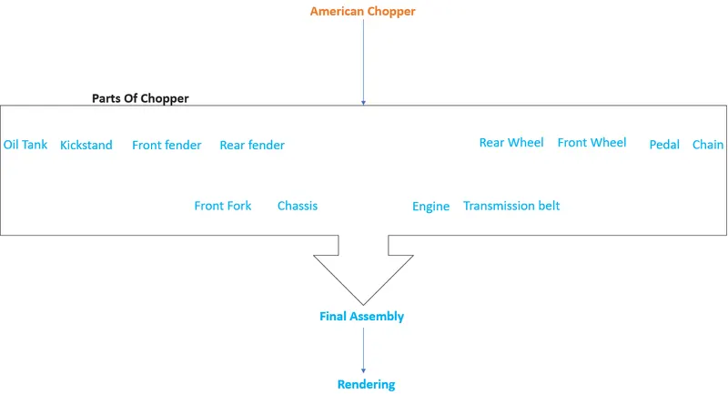
American chopper it is made by using different parts which model separately and then assembled in solidworks assembly layout. Parts list as below :-
- Transmission belt
- Kickstand
- Front fender
- Rear fender
- Oil Tank
- Pedal
- Chain
- Front Wheel
- Rear Wheel
- Front Fork
- Chassis
- Engine
- Gas Tank
Design methodology / approach
I have use the Bottom-up design approach which is the traditional method. We first design and model parts, then insert them into an assembly and use mates to position the parts.
1. Transmission belt :-
A belt drive is a transmission system that uses a flexible strip to transfer power. The turning disk is connected by a belt drive to the electric motor.
Tools/ Features used :-
Sketch tool :- Use to creates the 2d drawing.
Fillet :- It creates a rounded internal or external face on the part.
Boss Extrude :- To creates the extruded features.
Isometric view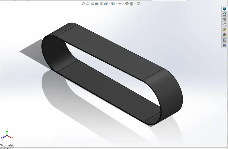
2. Kickstand :-
It is metal rod attached to a bicycle or motorcycle, lying horizontally when not in use, that may be kicked into a vertical position to support the vehicle when it is stationary.
Tools/ Features used :-
Sketch tool :- Use to creates the 2d drawing.
Fillet :- It creates a rounded internal or external face on the part.
Boss Extrude :- To creates the extruded features.
Dome :- Use to create dome like shape on the surface.
Loft :- It use for making transitions between profiles it can be a base,boss, cut, or surface.
Split Entities :- One sketch entity to create two sketch entities.
Isometric view
3. Front fender :-
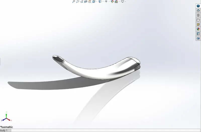
A fender is essentially a covering for your bike tires that protects you from the rain. Riding with fenders will prevent the rain from splashing a streak of muddy water up your back, over your shoes and on your face.
Tools/ Features used :-
Sketch tool :- Use to creates the 2d drawing.
Fillet :- It creates a rounded internal or external face on the part.
Revolve boss:- Revolves add or remove material by revolving one or more profiles around a centerline.
Split Entities :- One sketch entity to create two sketch entities.
Isometric view
4. Rear fender :-
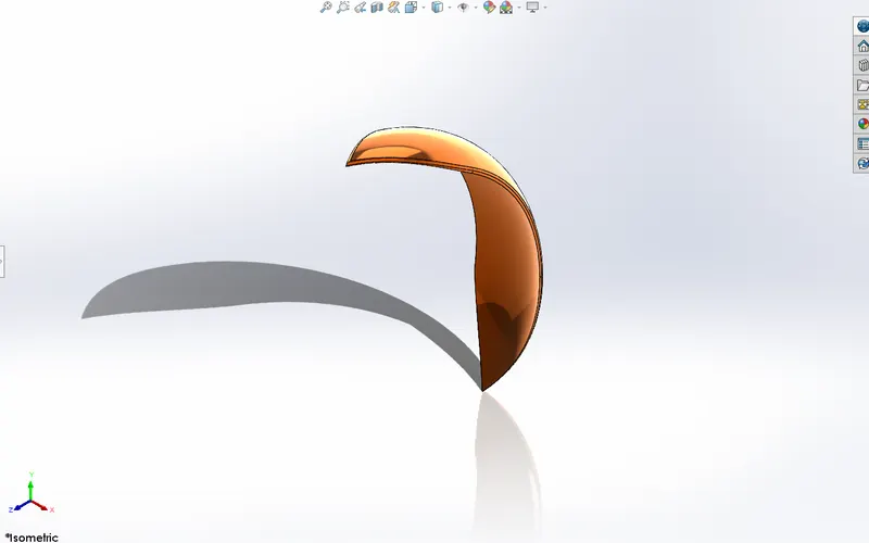
A fender is essentially a covering for your bike tires that protects you from the rain. Riding with fenders will prevent the rain from splashing a streak of muddy water up your back, over your shoes and on your face.
Tools/ Features used :-
Sketch tool :- Use to creates the 2d drawing.
Fillet :- It creates a rounded internal or external face on the part.
Revolve boss:- Revolves add or remove material by revolving one or more profiles around a centerline.
Shell :- It hollows out a part, leaves open the faces you select, and creates thin-walled features on the remaining faces.
Split Entities :- One sketch entity to create two sketch entities.
Isometric view
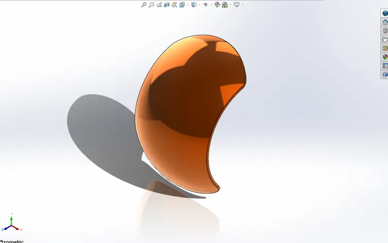
5. Oil Tank :-
A motorcycle oil tank is a tank that holds the capacity of oil used to cool the motorcycle.
Tools/ Features used :-
Sketch tool :- Use to creates the 2d drawing.
Fillet :- It creates a rounded internal or external face on the part.
Boss Extrude :- To creates the extruded features.
Combine body :- To combine multiple bodies to create a single body.
Shell :- It hollows out a part, leaves open the faces you select, and creates thin-walled features on the remaining faces.
Isometric View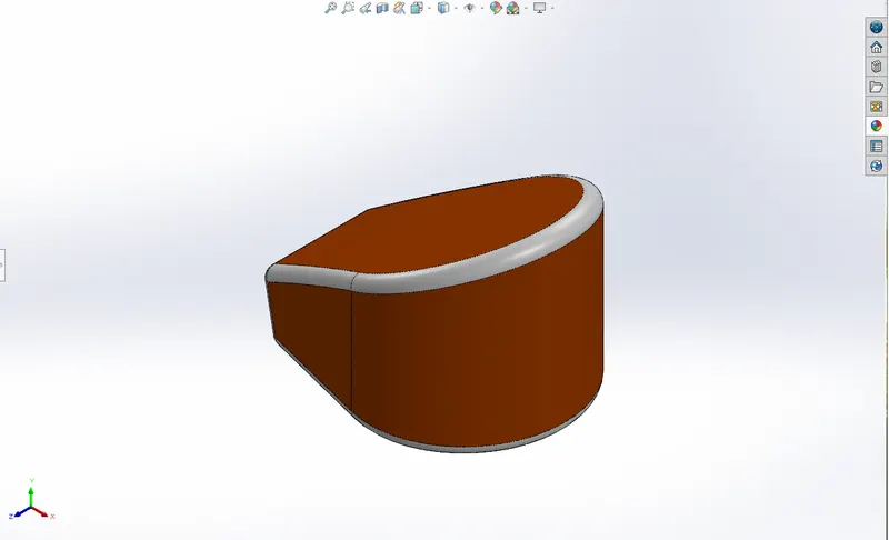
6. Pedal
Tools/ Features used :-
Sketch tool :- Use to creates the 2d drawing.
Fillet :- It creates a rounded internal or external face on the part.
Boss Extrude :- To creates the extruded features.
Revolve boss:- Revolves add or remove material by revolving one or more profiles around a centerline.
Dome :- Use to create dome like shape on the surface.
Chamfer :- The chamfer tool creates a beveled feature on selected edges, faces, or a vertex.
Linear Pattern :- To pattern one or more features along one or two linear paths.
Isometric View
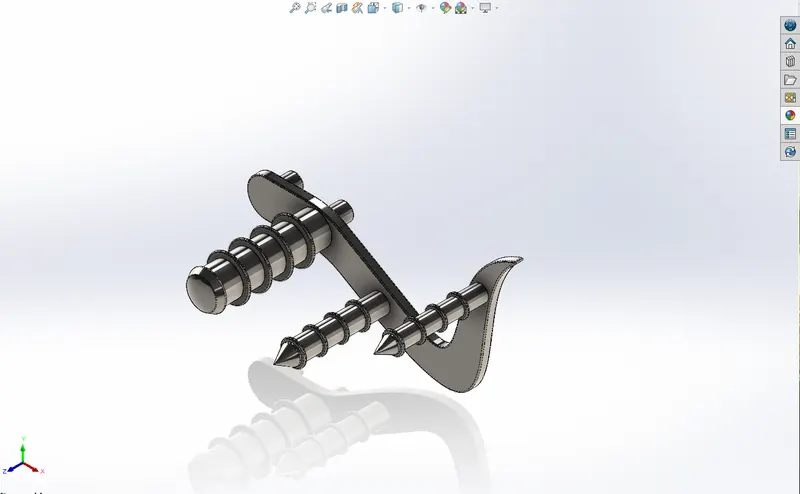
7. Chain :-
It used to transmit driving power to the rear wheel of a bicycle or motorcycle.
Tools/ Features used :-
Sketch tool :- Use to creates the 2d drawing.
Fillet :- It creates a rounded internal or external face on the part.
Boss Extrude :- To creates the extruded features.
Delete/ Keep Face :- Bodies to keep or delete using the Delete/Keep Body feature.
Circular pattern:- It use when we have a pattern one or more features around an axis.
Mirror :- To create a copy of one or more features, mirrored about a face or a plane.
Make Block :- Any single or combination of multiple sketch entities.
Isometric View
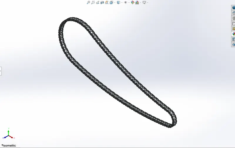
8. Front Wheel
Tools/ Features used :-
Sketch tool :- Use to creates the 2d drawing.
Fillet :- It creates a rounded internal or external face on the part.
Boss Extrude :- To creates the extruded features.
Revolve boss:- Revolves add or remove material by revolving one or more profiles around a centerline.
Chamfer :- The chamfer tool creates a beveled feature on selected edges, faces, or a vertex.
Circular pattern:- It use when we have a pattern one or more features around an axis.
Combine body :- To combine multiple bodies to create a single body.
Cut Extrude :- It removes material from a part or an assembly.
Revolved cut :- It allows you to cut a profile around an axis creating complex geometry in a single feature.
Isometric View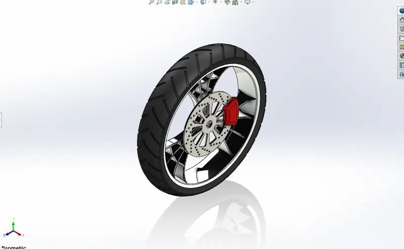
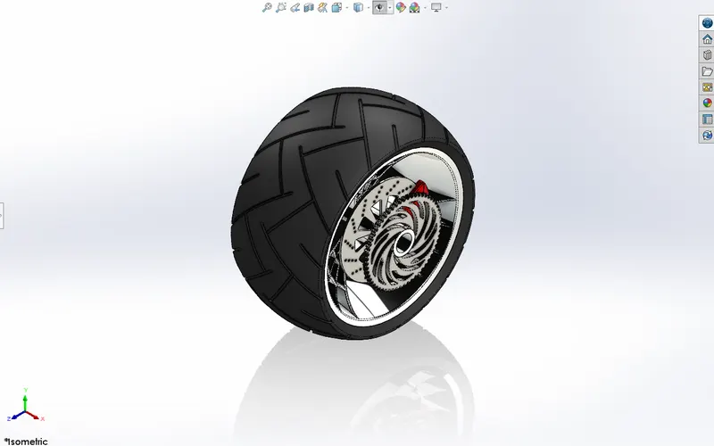
9. Rear Wheel
Tools/ Features used :-
Sketch tool :- Use to creates the 2d drawing.
Fillet :- It creates a rounded internal or external face on the part.
Boss Extrude :- To creates the extruded features.
Revolve boss:- Revolves add or remove material by revolving one or more profiles around a centerline.
Chamfer :- The chamfer tool creates a beveled feature on selected edges, faces, or a vertex.
Circular pattern:- It use when we have a pattern one or more features around an axis.
Combine body :- To combine multiple bodies to create a single body.
Cut Extrude :- It removes material from a part or an assembly.
Revolved cut :- It allows you to cut a profile around an axis creating complex geometry in a single feature.
Isometric view
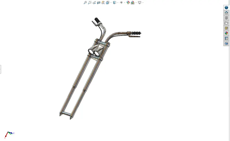
10. Front Fork
Tools/ Features used :-
Sketch tool :- Use to creates the 2d drawing.
Fillet :- It creates a rounded internal or external face on the part.
Boss Extrude :- To creates the extruded features.
Revolve boss:- Revolves add or remove material by revolving one or more profiles around a centerline.
Cut Extrude :- It removes material from a part or an assembly.
Revolved cut :- It allows you to cut a profile around an axis creating complex geometry in a single feature.
Linear Pattern :- To pattern one or more features along one or two linear paths.
Combine body :- To combine multiple bodies to create a single body.
Reference plane :- To make the plane.
Sweep :- It creates a base or surface by moving a profile along a path.
Projected curve :- To project a sketched curve onto a model face to create a 3D curve.
Dome :- Use to create dome like shape on the surface.
Move/Copy Bodies :-Itmove, rotate, and copy solid and surface bodies, or place them using mates.
Isometric view
11. Chassis
Tools/ Features used :-
Sketch tool :- Use to creates the 2d drawing.
Fillet :- It creates a rounded internal or external face on the part.
Boss Extrude :- To creates the extruded features.
Revolve boss:- Revolves add or remove material by revolving one or more profiles around a centerline.
Combine body :- To combine multiple bodies to create a single body.
Reference plane :- To make the plane.
Sweep :- It creates a base or surface by moving a profile along a path.
Projected curve :- To project a sketched curve onto a model face to create a 3D curve.
Dome :- Use to create dome like shape on the surface.
Chamfer :- The chamfer tool creates a beveled feature on selected edges, faces, or a vertex.
Split Entities :- One sketch or boby entity to create two sketchor body entities.
Isometric View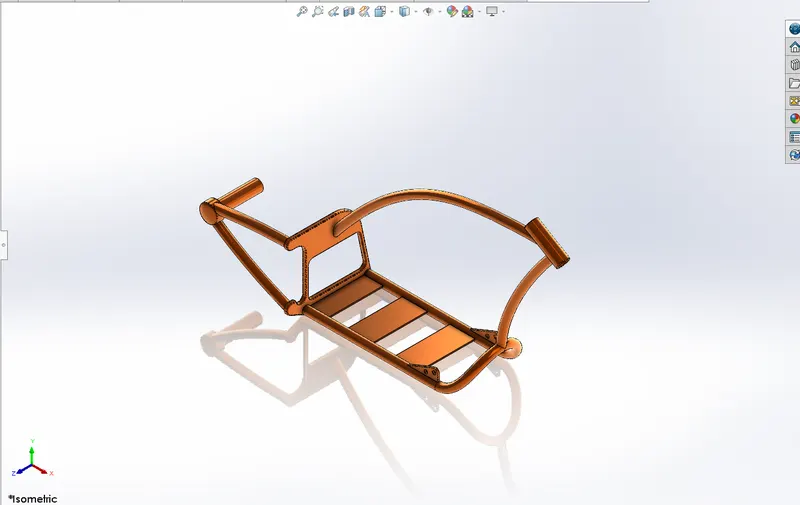
12. Engine
Tools/ Features used :-
Sketch tool :- Use to creates the 2d drawing.
Fillet :- It creates a rounded internal or external face on the part.
Boss Extrude :- To creates the extruded features.
Combine body :- To combine multiple bodies to create a single body.
Reference plane :- To make the plane.
Sweep :- It creates a base or surface by moving a profile along a path.
Projected curve :- To project a sketched curve onto a model face to create a 3D curve.
Dome :- Use to create dome like shape on the surface.
Chamfer :- The chamfer tool creates a beveled feature on selected edges, faces, or a vertex.
Split Entities :- One sketch or boby entity to create two sketchor body entities.
Linear Pattern :- To pattern one or more features along one or two linear paths.
Circular pattern:- It use when we have a pattern one or more features around an axis.
Reference plane :- To make the plane.
Isometric View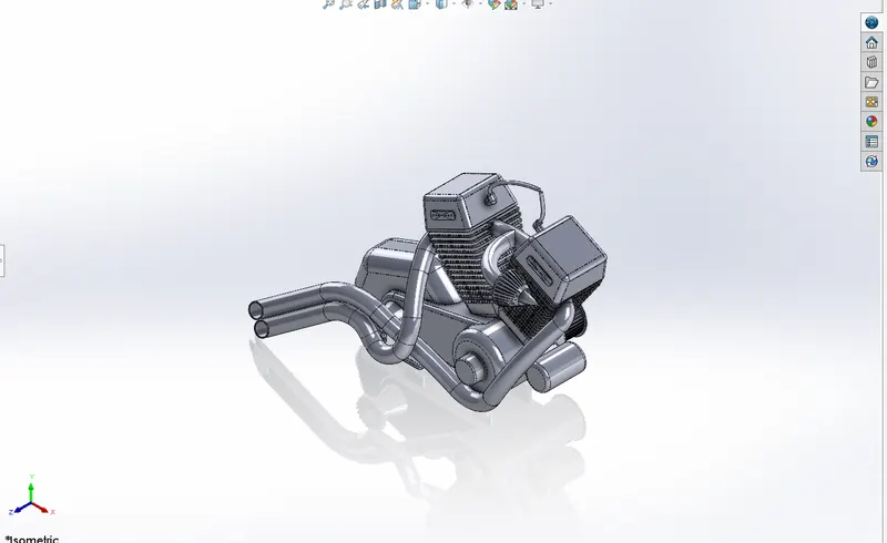
13. Gas Tank
Tools/ Features used :-
Sketch tool :- Use to creates the 2d drawing.
Swept surface:-To create a swept surface.
Reference plane :- To make the plane.
Trim Surface :- Use a surface, plane, or sketch as a trim tool to trim intersecting surfaces.
Loft surface :- It use for making transitions between profiles it can be a base, boss, cut, or surface.
Boundary surface :- To create surfaces that can be tangent or curvature continuous in both directions.
Fillet :- It creates a rounded internal or external face on the part.
Knit Surface:- Use tool to combine two or more faces and surfaces into one.
Boss surface :- Extruding Surfaces from a 2D or 3D Face.
Mirror :- To create a copy of one or more features, mirrored about a face or a plane.
Isometric View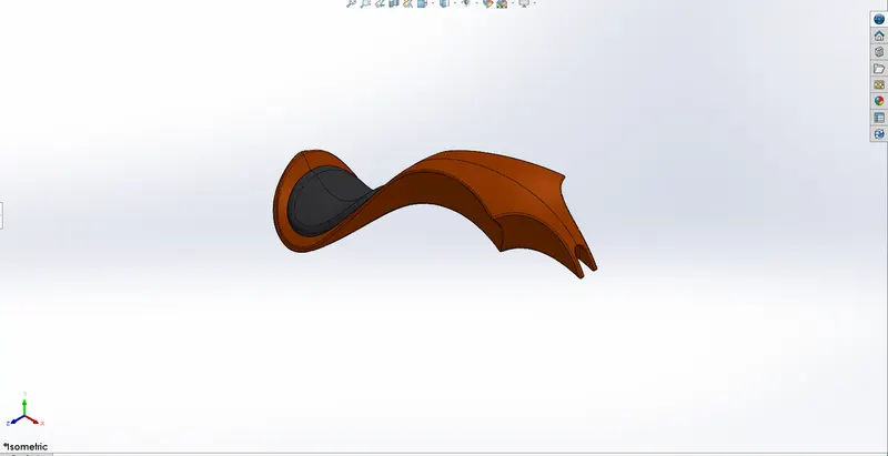
Assembly :-
In the assembly we add the parts one by one and giving them mates to place in the assembly.
Mates :-
In the assembly of the we use some mates to get proper position of the part in the model some of them are follow :-
1. Coincident mates
2. Concentric mates
3. Distance mates
4. Tangent mates
5. Parallel or Perpendicular mates
6. Symmetry mate
7. Width mate
Isometric View
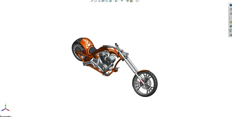
Both Side View
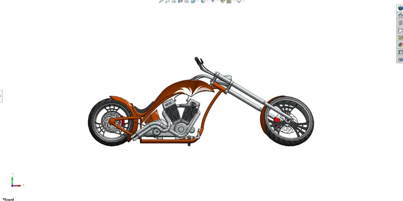
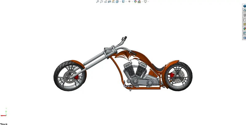
Front View Back View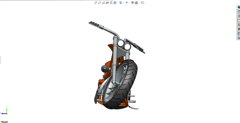
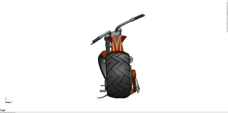
Rendering
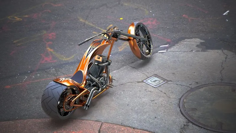
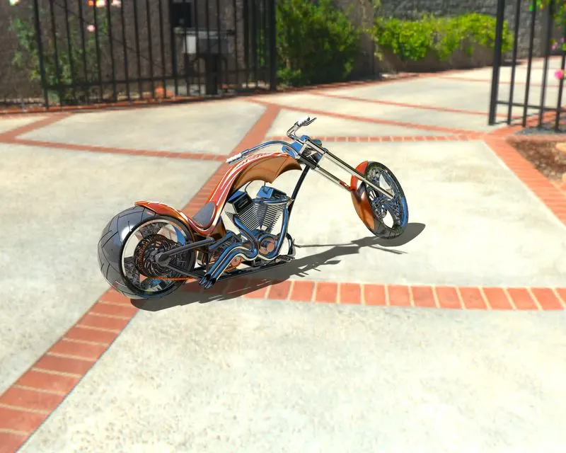
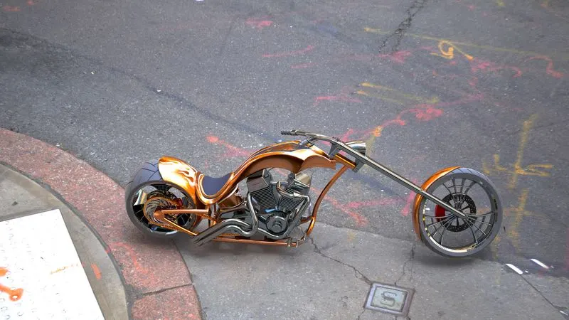
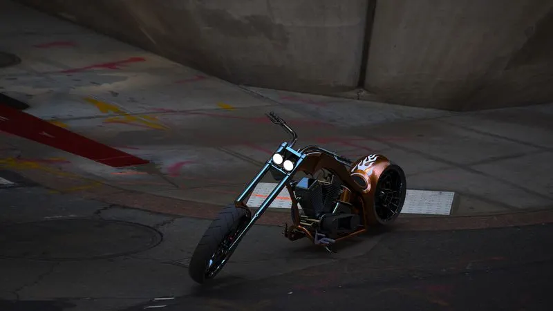
I have done the rendering on the photoview 60 and SOLIDWORKS Visualize some image as
Follow :-
photoview 60 :-
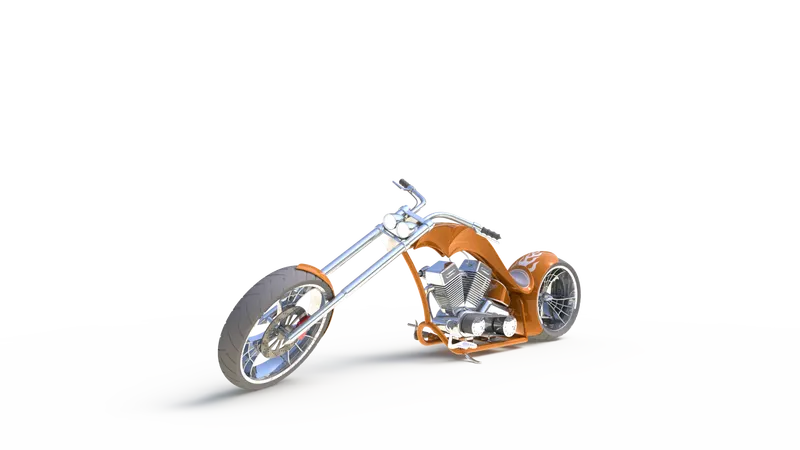
SOLIDWORKS Visualize :-
Conclusion :-
All the parts of the American Chopper were modelled and assembly was created using the solidworks and by using the photoview 60 and SOLIDWORKS Visualize rendering is done.