Photo Realistic Rendering
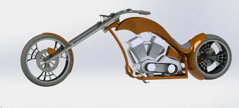
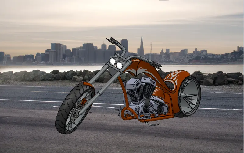
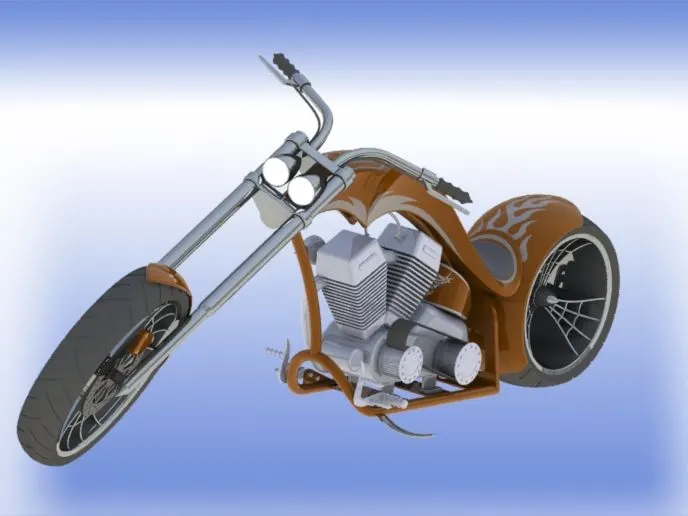
AMERICAN CHOPPER BIKE MOEDLING IN SOLIDWORKS:-
Objective :-
- Creating advance chopper bike due to understanding advance solidworks interface
- Understanding advance function of solidworks for high speed work interface
- Understanding key feature of assembly while assemble of all part chopper bike
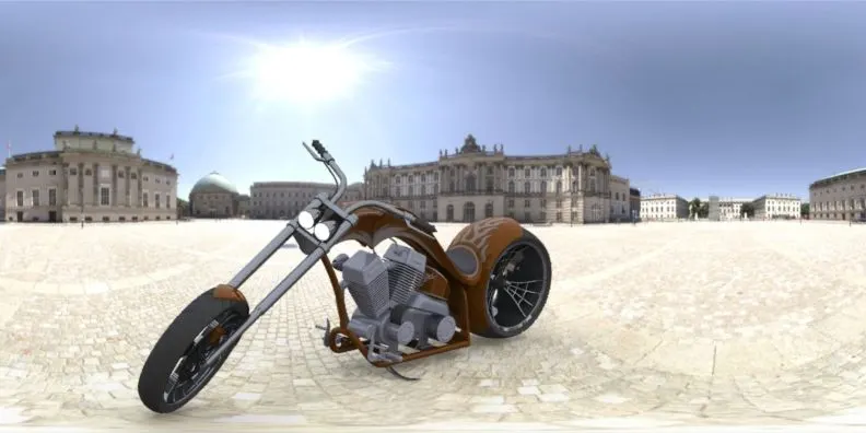
- Understanding photorealstic reandering chopper bike in solidworks in photorealistic 360
Introduction:-
This is harley devidson chopper bike own by harley devudson company which is build i 1903. The chopper bike is custom representation of harley bike. in this bike they custom mainly handle, gas tank, and a total power of 60.00 hp (43.8 kw) 6000 rpm with an v-twin 4-stroke engine. its almost maximum speed 144.8km/h and the harley devidson chopper bike weight has 272.2kg.
Design methodology
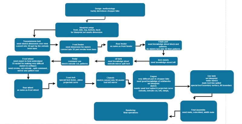
- Transmmision belt
- Kick stand
- Front fender
- Rear fender
- Oil tank
- Chain
- Pedal
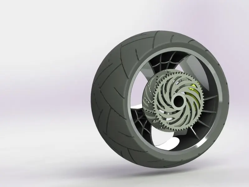
- Front wheel
- Rear wheel
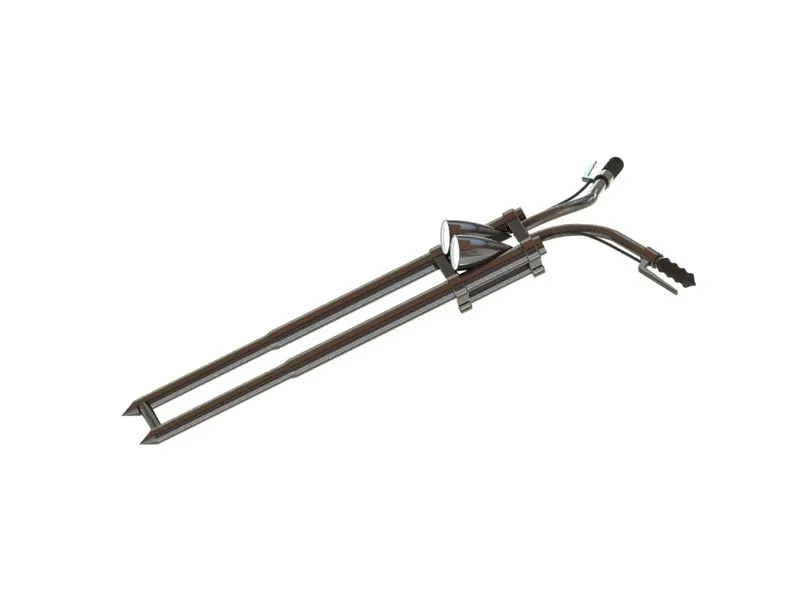
- Front fork
- Chassis
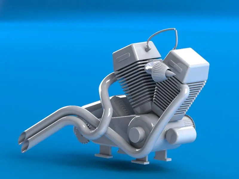
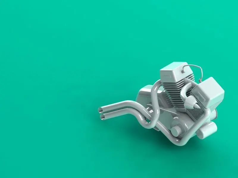
- Engine
- Gas tank
Transmmions belt
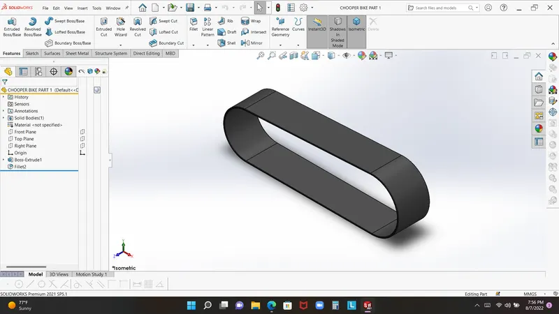
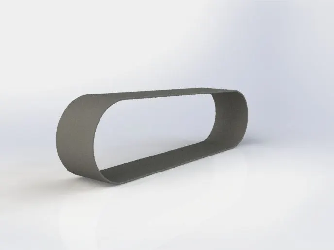
Transmmions belt used in bike for power transmmions between engine and motor. this is the first part which we create in solidworks softwere. this belt is 88 mm width and 490 mm long which is located in engine pulley to motor pulley .
Features and tool which is uesd in creating transmmision belt
- Sketch
- line
- Three point arc
- offset tool
- Extrude boss base
- fillet
- Appereances
Method which is used
- Open solidworks softwere and change ips into mm becouse which create every model in mm.
- salect plan and open sketch of front plane in which we draw sketch by the line and three point arc
- draw 350mm long line and connected by three point arc which 70 mm redius do anothere arc as same redius and joimt by the single line.
- now our first sketch ready we gonno go for offset for 3.5mm
- now exit to sketch and ready to extrude boss base
- click on the extrude boss base in the command manneger nd extrude the sketch 88 mm
- this finale of our model but we have to give it 1 mm fillet
- go to the fillet option and give it 1 mm fillet used advance option so filliting the model both side
Kick stand
Kick stand is veary small part in thid model. it is look like side stand which is used to support the bike while no one controling it
Features and tool which is used for creating the side stand
- sketch
- line
- center line
- circle
- loft
- extrude boss base
- extrude cut
- dome
- fillet
- split commande
- appeareance
Main feature and tool specification
Loft:- insert-feature-loft or see in the feature maneger
loft is used bassically for rounding and line or sketch which is interconnected to profile and guide curve. so open loft in which feature manneger and select profile then selecte guide curve like line or splind.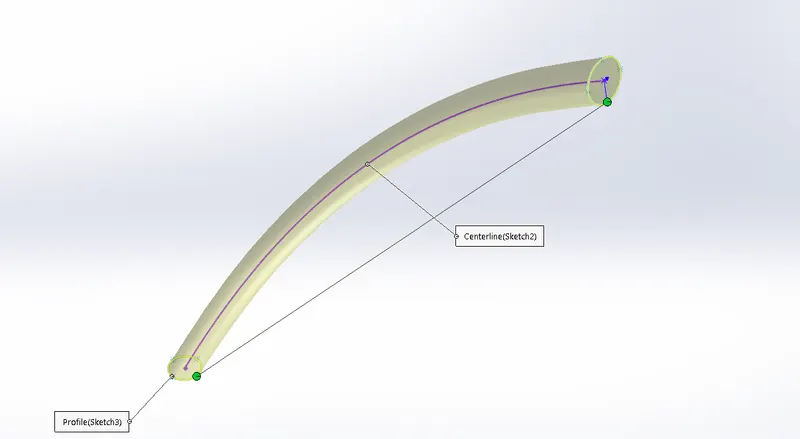
Extrude boss base:-
This is very pretty tool in cad extrude boss base. it is mostly used in convert the sketch into 3D model.
like user draw rectangle circle squre or any 2D frame this tool convert into 3D part. so how it is used fosrt of all user create a 2D frame than go to feature manger and click on extrude boss bas select the profile and give them dimension.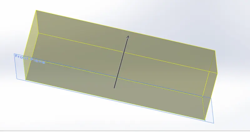
Extrude cut:-
Extrude cut as same as work in extrude boss base. but littile bit diffrence between them. this tool used for cut the solidpartas same proceducre like extrude boss bass. user first create some 2D profile then convert into 3d. now we have make sketch on the where we want to cut the part.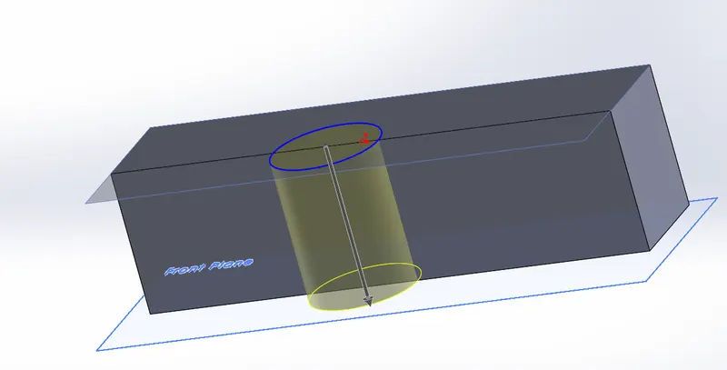
Dome:-
Dome feature used for dome profile om any 3Dpart or model. this tool is in insert feature where user can find it.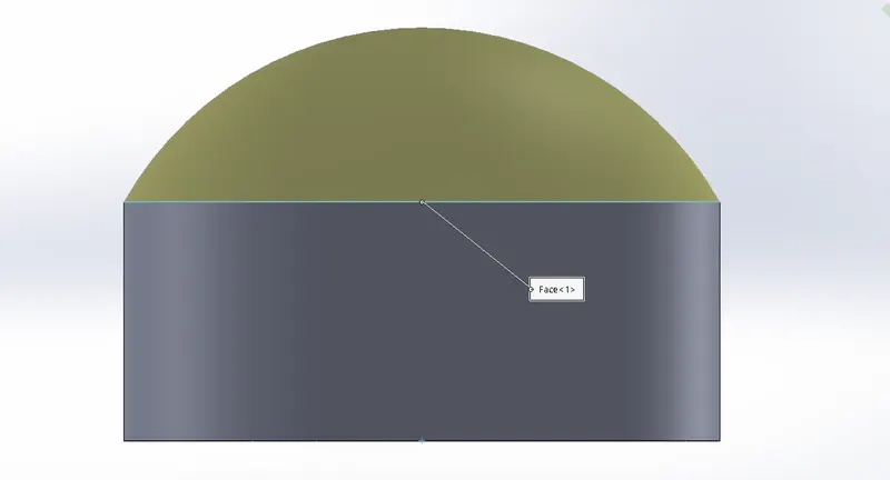
Procedure of creating kick stand
Open solidworks select front plane. sletch ellipse on the front plane with 18 mm next sketch on the mid plan which is splind so used have to create a splind 110mm with and 220 mm long. now time to use refrence plan go to feature manessger. this plan use for second profile for kick stand user create a ellipse with 30 mm. now we loft the whole profile. go to insert feature and select the loft command use it try to selecte fisrt two ellips and now create guide curve click ok.
goto dome option and give it dome for both side.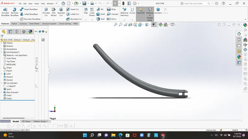
Front fender
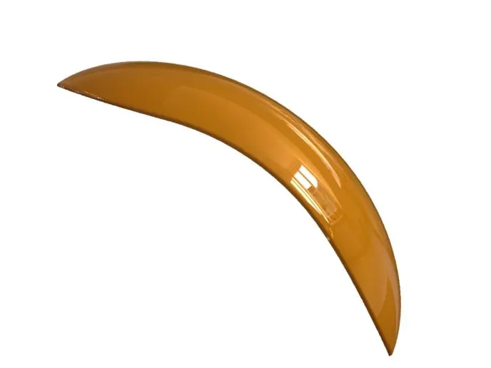
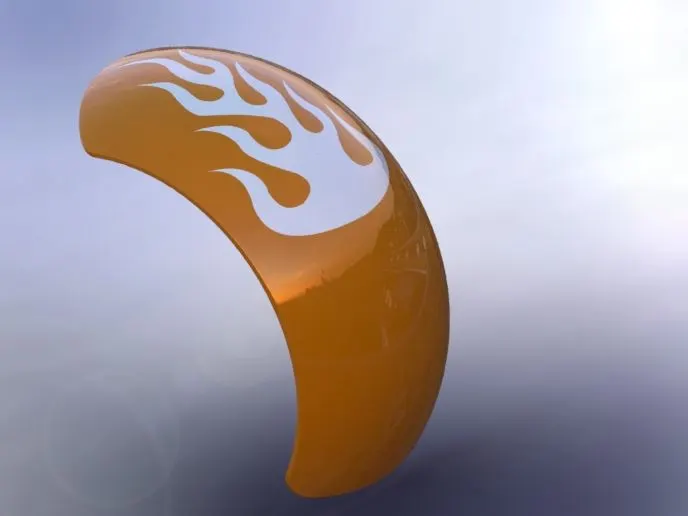
Front fender use for cover up try wheel so any mud should not fly over the rider. this is very basic part of bike or any car design.
Main feature or tool used
- Sketch
- offset enitties
- three point arc
- revoke tool
- slite tool
- mirror
- appereance
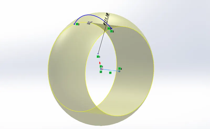
Revoke tool
splite tool
Split tool used for seprating the two part, for split tool user go to feature maneger -insert- feature
open the tool selected the sketch in which user want to cut the and click on the cunsume, if you dont want to cunsume that the model seprete into two part.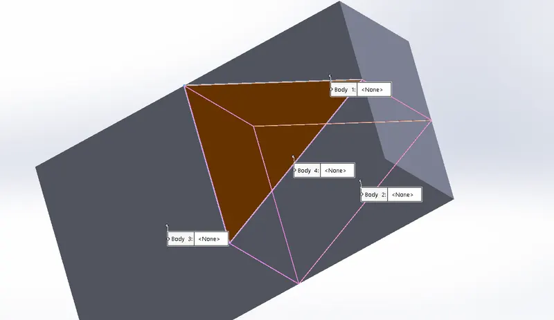
Front fender
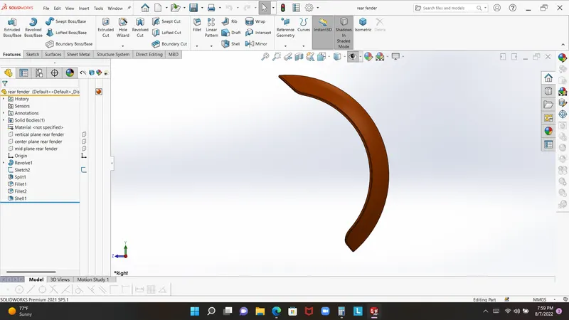
open the solid works change ips into mm and selecte plane. now draw a center line which horizontal with the centre point now draw an three point arc give radius 290mm. make sure that arc centre point horizontal with the origine point and give distance with it. now revoke it.
used split command due cut the part by angle and final five fillet
Rear fender
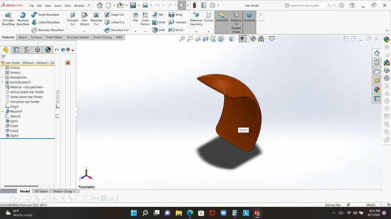
Front fender use for cover up try wheel so any mud should not fly over the rider. this is very basic part of bike or any car design.
Main feature or tool used
- Sketch
- offset enitties
- three point arc
- revoke tool
- slite tool
- mirror
- appereance
Oil tack
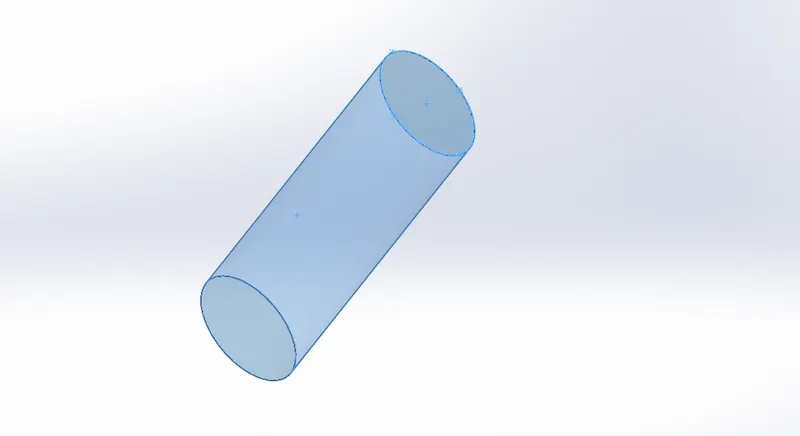
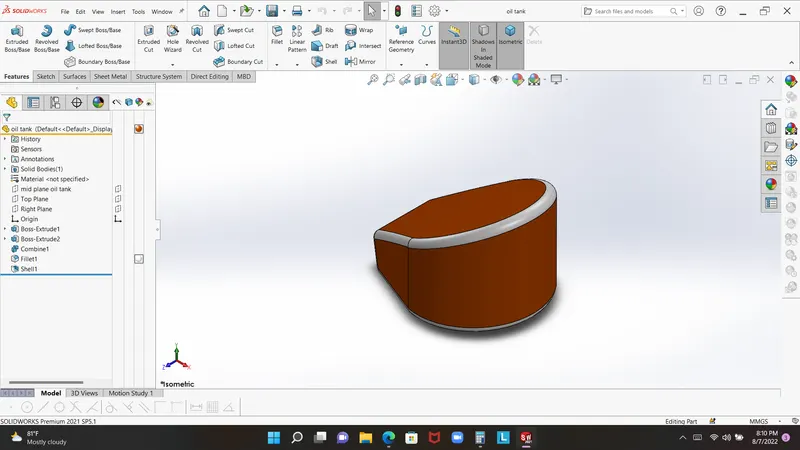
oil tank used for storing the oil, oli is very important lubricant for any machine or moviable thing so this is must needy for engine and piston
Mian feature and tool
- Sktech
- line
- three point arc
- extrude boss base
- split tool
- fillet
- shell
shell :- feature used when user need to hollow any part by the in side
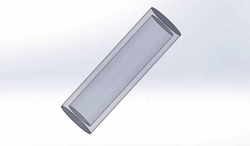
Oil tank
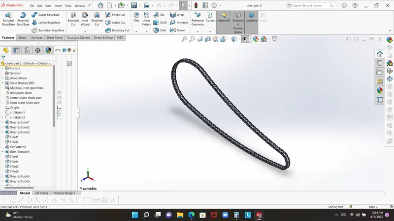
Chain part
For modeling 3D chain part it is very complex in any softwere so that it like have multiple body which is movable or self adjectable. basically chain use for give the transmmision power to small spoket to the rear wheel.
Main feature and tool
- Sketch
- Trim
- Fillet
- Blocks
- Extrude
- Patterns
- Appearances
Patterns:- patterns is save your lots of time due this feature creating many body in single step, it may be curve, lineare, guide curve, point selection.
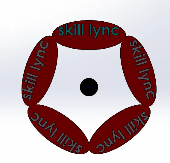
Chain part
lunch solidworks open new part and convert into mm so there is no problem according to dimension
select front plane make sketch draw profile like slot, extrude it selet face sketch make two circle which horizontale by the slot
give extrude, mirrore it in form for chain part.
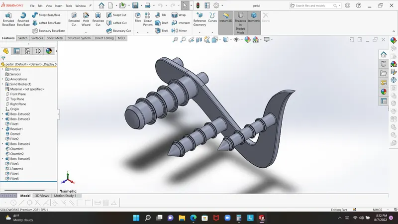
Pedal
Pedal is extrnal part of bike which is suport the bikers leg and gear , break blow in the pedal so biker can easly control the bike
Mian feture and tool
- Sketch
- Extrude
- Fillet
- Linear pattern
- Dome
- Chamfer
- Appearances
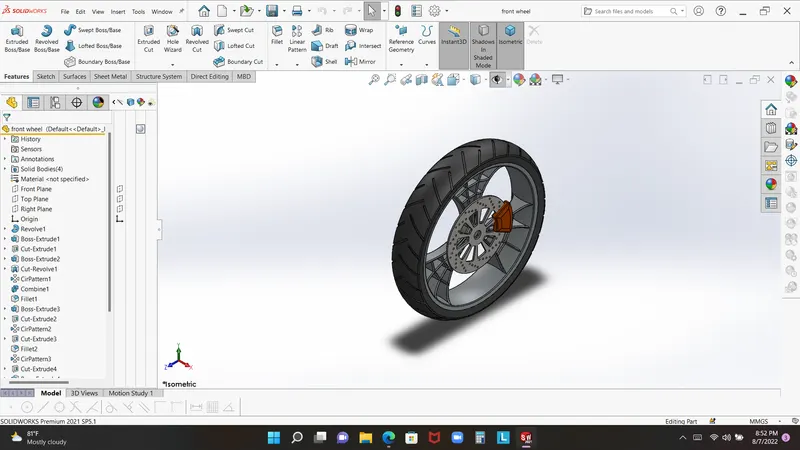
Front wheel
Main features and tool
- line
- splind
- three point arc
- revoke boss bas
- ectrude boss bass
- extrude cut
- fillet
- chamfer
- split tool
- circuler pettern
- combine
- appereance
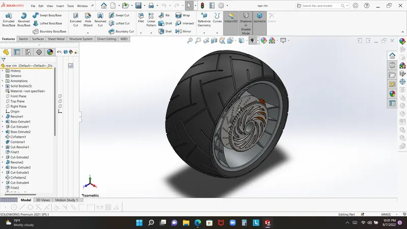
Rear wheel
Main features and tool
- line
- splind
- three point arc
- revoke boss bas
- ectrude boss bass
- extrude cut
- fillet
- chamfer
- split tool
- circuler pettern
- combine
- appereance
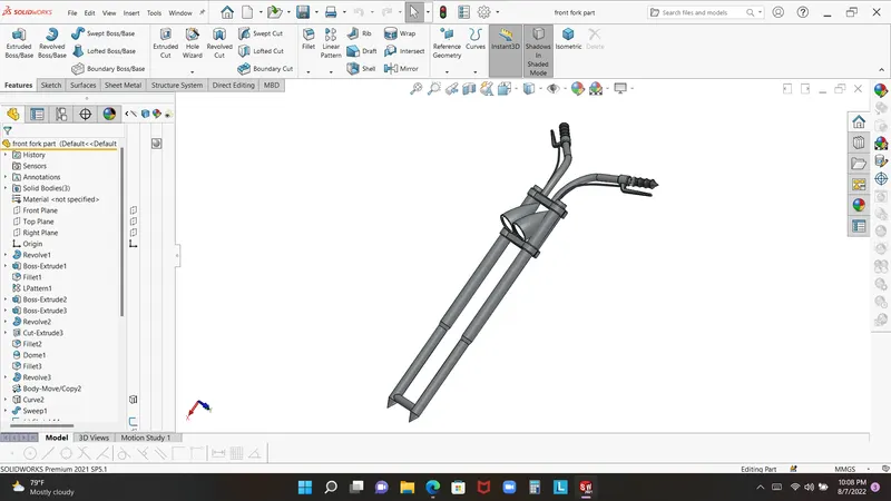
Front fork
Mian features and tool
- Sketch
- Extrude Boss bass
- Trim command
- Revolve boss bass
- Split tool
- Planes
- Convert entities
- Move/copy body
- Dome
- Mirror
- Combine
- Extrud cut
- Curve
- Sweep
- Appearences
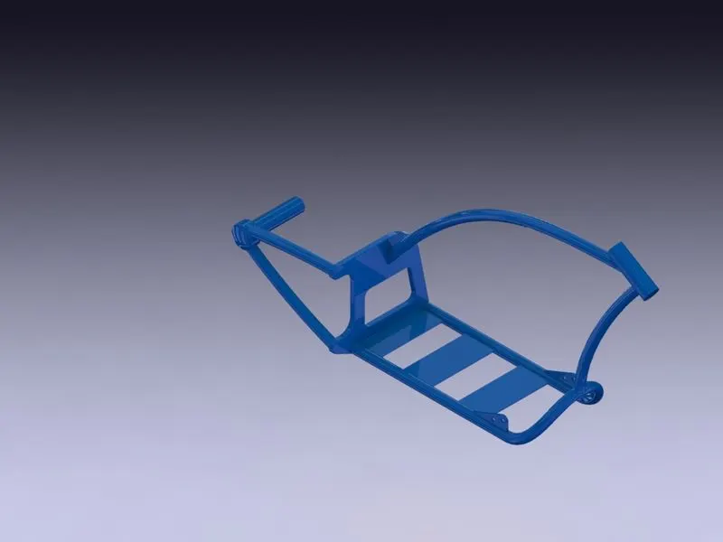
Chassis
Main features and Tool
- Sketch
- Offset
- Convert entities
- Project curve
- Trim
- Planes
- Sweep
- Split
- Revolved extrud
- Extrud cut
- Fillet
- Combine
- Appearences
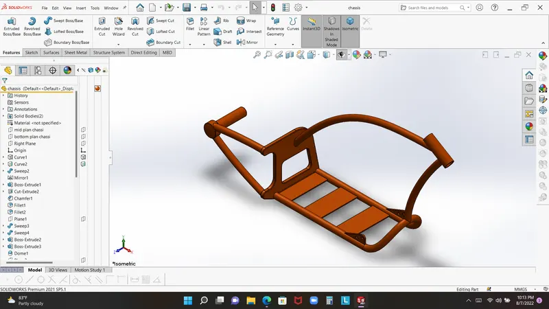
Engine
main features and tool
- Sketch
- Offset
- Convert entities
- Project curve
- Trim
- Planes
- Sweep
- Revolved extrud
- Extrud cut
- Fillet
- Combine
- Composite curve
- Circular pattern
- Mirror
- Dome
- Sweep
- Appearences
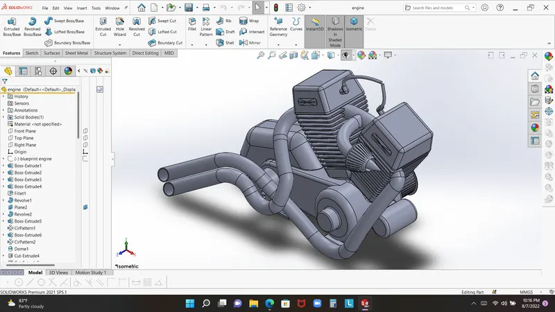
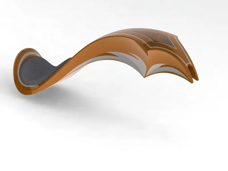
Gas tank
Main features and tool
- Sketch
- Offset
- Convert entities
- Trim
- Planes
- Sweep surface
- Loft surface
- Fill surface
- Fillet
- Surface trim
- Surface knit
- Sweep cut
- Mirror
- Appearences
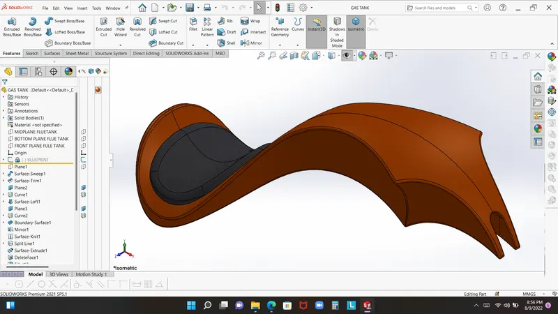
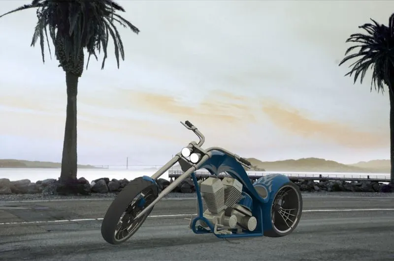
Assembly
in assembly this is nost important part of this bike
Mian features and tool
- concident
- with mate
- advance mate
- plane mate
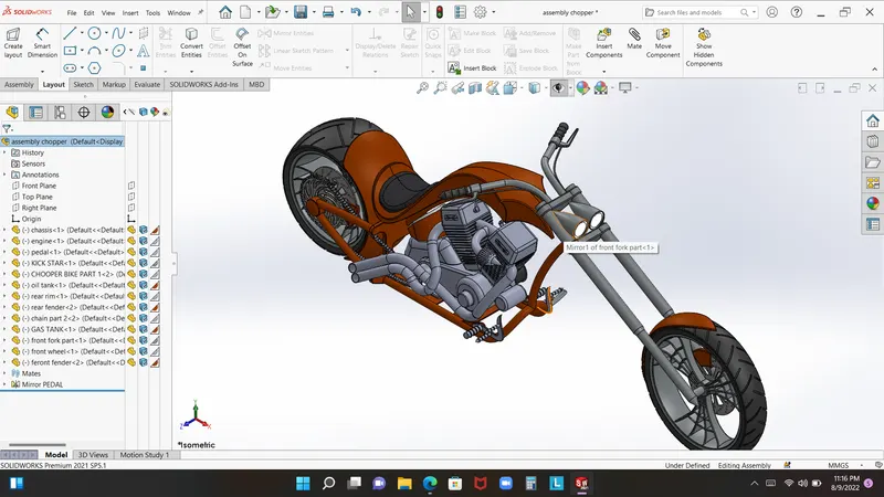
conclusion:-
hard work+dedication make this great project with best trainer.....