Aston Martin ONE-77 Challenge-11 (Project) Final Assembly
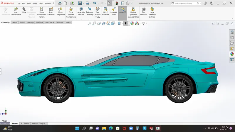 Title:- Aston martin car one 77 designing in solid works software
introduction:- in the advance cource user build aston martin car one 77. this car is highly advance and good result of best engineers hardwork. aston martin car has 2 door and 2 seat one 7.3 literfour cyllinder engine which is produce 750 hourse power. the cachis of this car made by high pressure sustainable carbon fiber. car has v12 engine which is most powerfull engine in the wold. this engine gives car six speed of transsimaition. what is modeling of this car so in this car boundary surface is main fouce and some point user used part modeling like tyre rim break and bush.
Modeling steps
- blueprint setup
- Roof surface
- Side surface
- tyre feader surface
- back and front surface
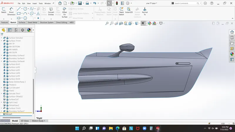
- door and front wing
- hood window part
- light
- grile
- weel break
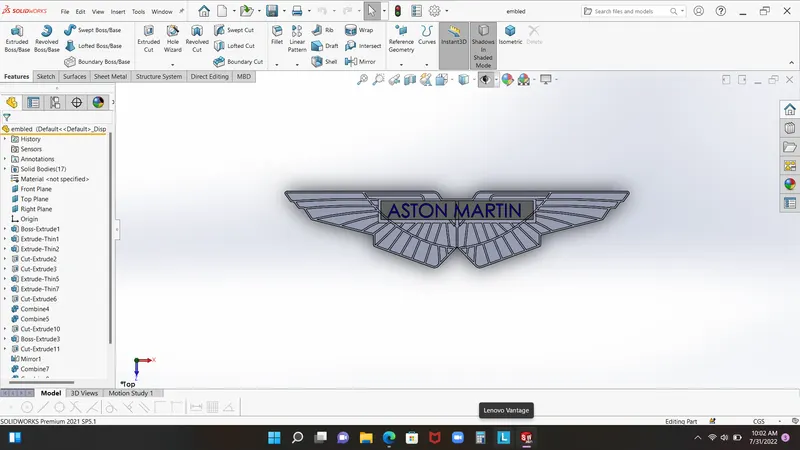
- emblem
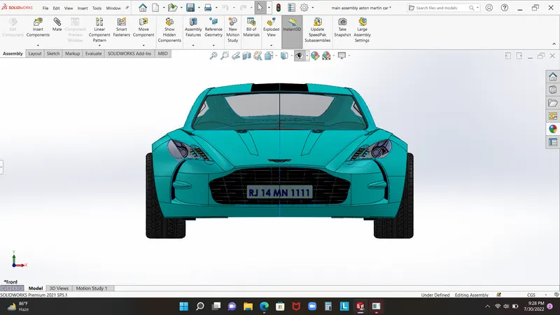
- assembly
Objective:-
- To modeling adavnce car in solidwork so fimiler with solidworks interface
- to create an idea with help of solidwork
- to improve design skill
- grape best oppoturnity in the design world
Design approch
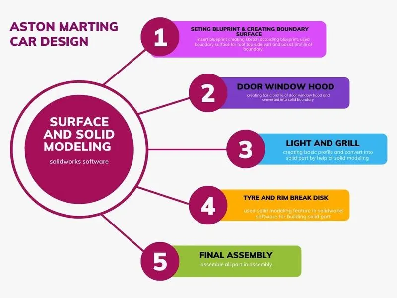
basically aston marin car design approch in two diffrent part surface modeling and part modeling
Surface modeling:-
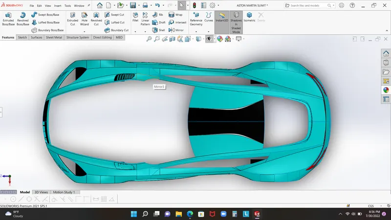
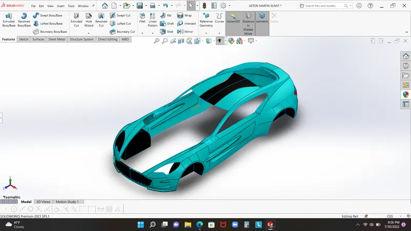
Surface modeling is making all surface like roof, side,back, front, hood by the help of boundry surface extrude surface cut surface fill surface trim command, these are all tool which is used in creating boundry for car model
Solid modeling:-
solid modeling is easy as comperition surface modeling so some point we used solide modeling in like break disk and tyer rim, grid, light work. in the solidworks solidmodeling is quite easy that why making solid model is less time cunsuming.
Flowchart
Main solidwork feature used for building aston martin car
- Sketch Picture
- Projected Curve
- Boundary Surface
- Lofted Surface
- Ruled surface
- Extend surface
- Extrude surface
- Filled surface
- Knitted surface
- Split line
- Split
- Delete face
- Delete body
- Offset surface
- Move/Copy Bodies
- Cut with surface
- Thicken
- Extrude Boss/Base
- Revolved Boss/Base
- Revolved cut
- Swept cut
- Linear Pattern
- Circular Pattern
- Curve driven Pattern
- Fillet
- Combine
CHALLENGE:- 1
The first challenge is regarding of set the all four type blueprint front side top and rear blueprint. the sets of blueprint is most importane part becuse of this is give us all over size of car dimension, so for settinf of print is fist of all we open the new part in solid works and convert ips into cgs. now click on the right side view and turn on sketch. got to the insert in features maneger and insert picture image of side print. adjust the size of print and give some transprentcy. similer as we do with two print like top and front. now for rear print we will make a refrence plane which is base of rear blueprint.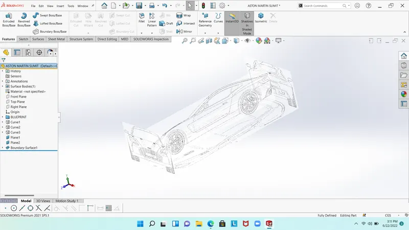
CHALLENGE:- 2
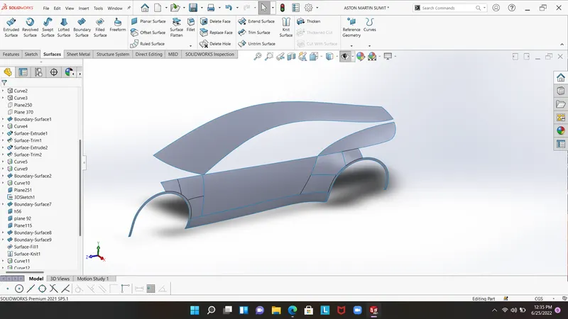
Now we are in secound challenge in this challenge we have work with some other tool like line, splinde and projected curve, this is gerneral tool. we had used some advance tool like boundary surface and surface fill, cut surface. start with side plane, we used some splinde and create an viewport according to blue print for making top boundry of car. for making the boundry we need to make perpendicuer sets of line and splinde with coincide relation. now time to used boundary surface. in boundary surface need to salecte two direction direction 1 and direction 2. some times need to add mearge result of trim as direction to set boundary as requred as per disign
MAIN TOOL:-
LINE , SPLINDE, PROJECTED CURVE, TRIM COMMAND, BOUNDARY SURFACE, SURFACE FILL, SURFACE EXTRUDE, ROUND&FILLETE, KNIT BODY.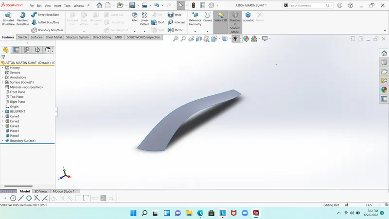
CHALLENGE:- 3
In challenge three we will making the front and rear bumper of the aston martin car. for crafting the bumper we need as similer sketch tool and surface tool which is use in top and side part of car. so we need to create sketch according to blue print. use surface boundry as create boundary of bumper in this part we intruduce with a new part name as rulede surface. ruled surface is tool which is used to create a perpendiculerr surface right of boundary surface. like when we need to make boundary as a perpendiculer of surface. one another tool which used many time in this part name as offset surface. offset surface tool used for making a copy surface.
MAIN TOOL:- BOUNDARY SURFACE, FILLET RULED SURFACE, CUT SURFACE, SPLIT TOOL, LINE , SPLINDE, PROJECTED CURVE, TRIM COMMAND, BOUNDARY SURFACE, SURFACE FILL, SURFACE EXTRUDE, ROUND&FILLETEBODY. 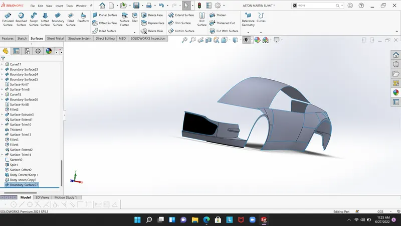
CHALLENGE:-4
HOOD & WINDOW
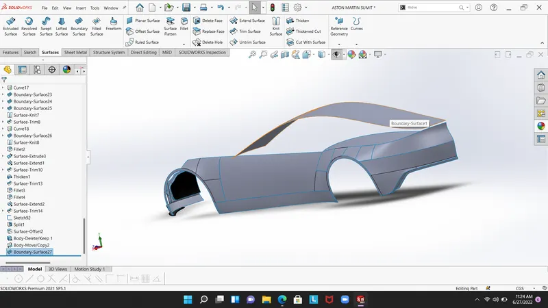
IN SECOND CHALLENGE WE DID HAD MADE TOP OF THE CAR. NOW IN THIS CHALLENGE WE CUT THE SURFACE FOR HOOD BY THE USED SLITE COMMAND TOOL. FISRT CREATED SKETCH BY SPLIND AND LINE THEN WE USED SAPREATED TWO SURFACE BY SLIT TOOL. NOW WE UESD BOUNDARY SURFACE FOR MAKING SURFACE. SKETCH HOOD BY SPLIND AND LINE TOOL GIVE A DIMENSION FOR UNDER DEFINED SKETCH. UESD SURFACE BOUNDARY.
WINDOW
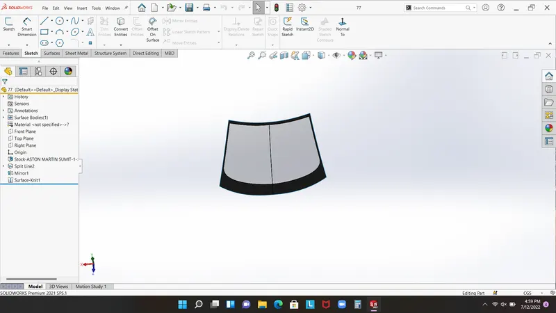
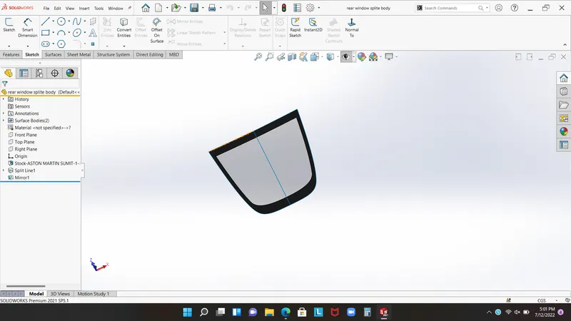
Fist link the roof with rear surface of car. for this create refrence plan splind intersection curve and convert entity make piaers realtion and trim the unwaned part. its too hard process for making window so we have to create many surface boundry as used tool which i mention earlier.
MAIN TOOL
Splind tool surface boundry trim command intersection curve projected curve.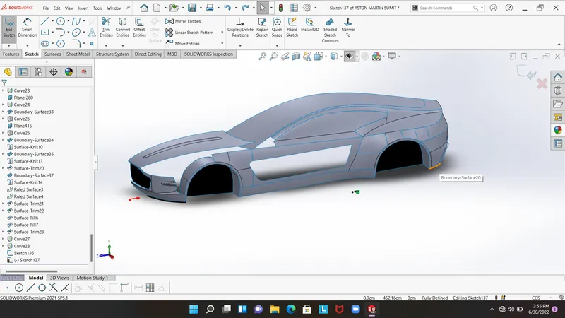
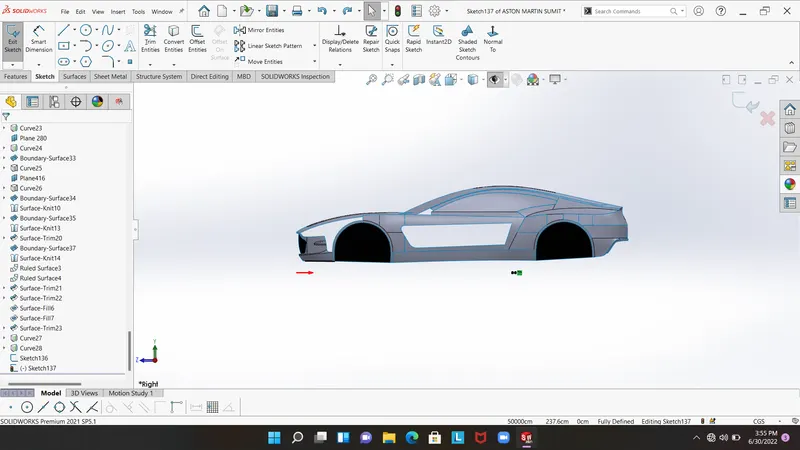
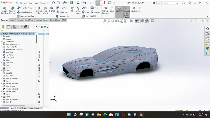
feature used in hood window Windshield Rear Window
inserted into new part as copy from main body
spilt
split tool
surface boundry
extrude boundry
fill surface
trim
cut surface
ruled surface
loft body
delet body move
intersection feature
boss base extrude
Images of all part 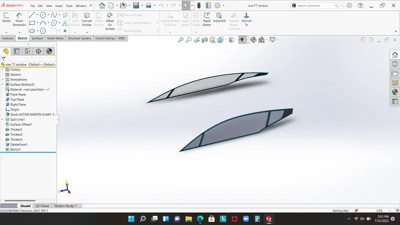
Grille
In the any car manufractures used grille as realising heat which leave from engine. so engine is high speed moving part.in this model used both concept as solid modeling and surface modeling to create a grille part. from begin to star first draw sketch as according blueprint make both side boundary. now used boundary off set as per 0 cm and ut the surface according to grille. now make name plate is too easy used extrude boss base by the creating rectangle.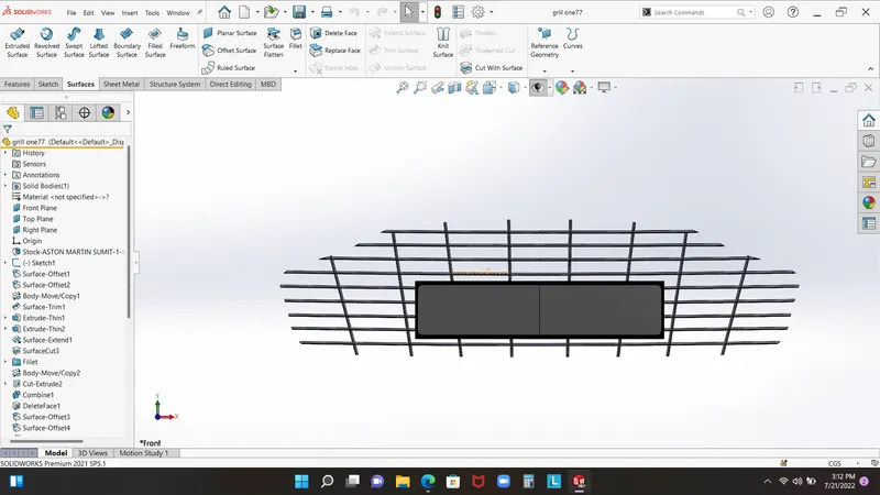
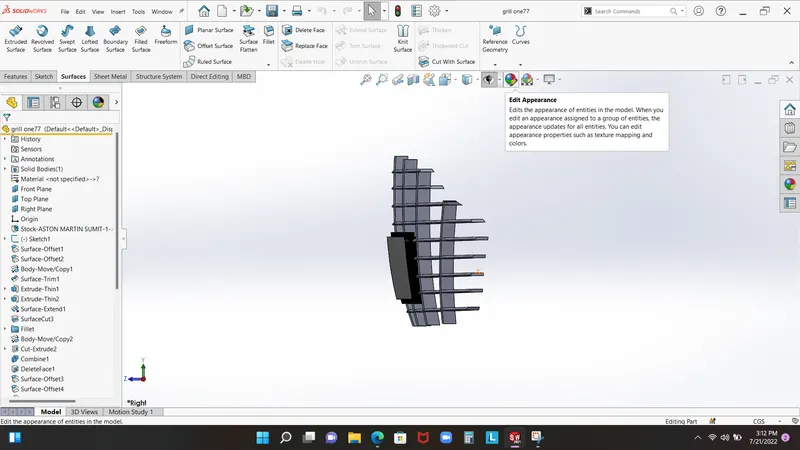
Grille features
- split tool
- Insert into new part
- boundary surface
- variable radius fillet
- Move/Copy bodies
- Thicken
- cut with surface
- Revolve
- Split line
- Extrude Boss/Base
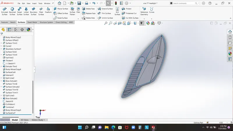
light and wheel assembly 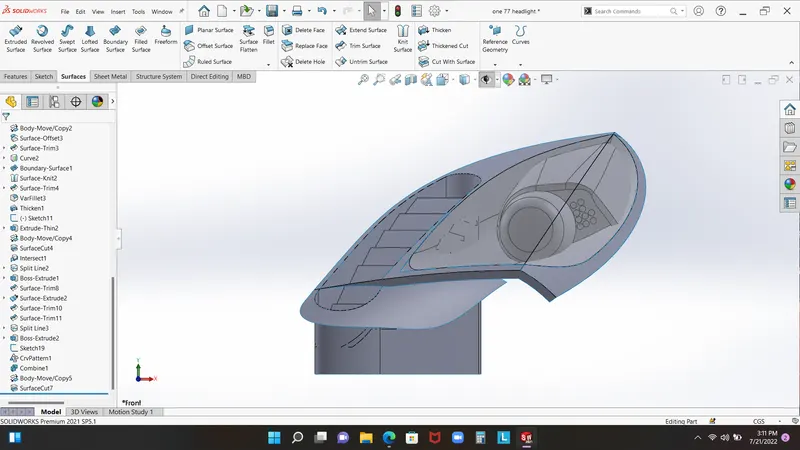
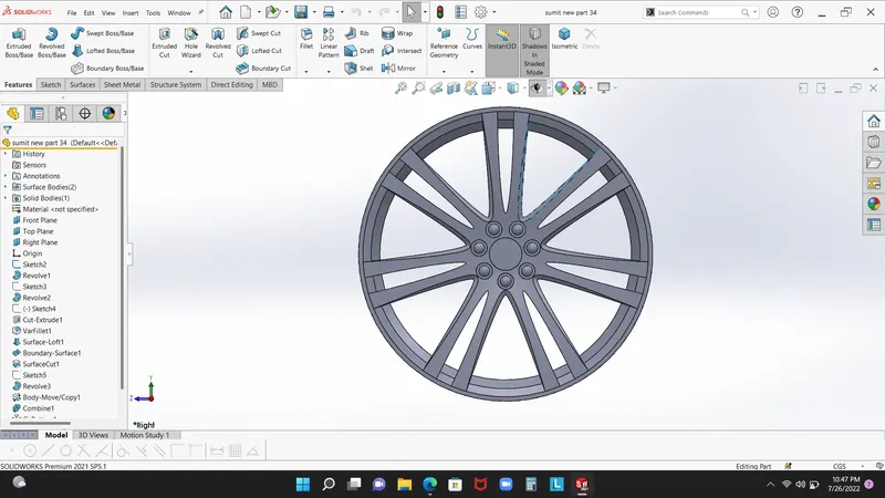
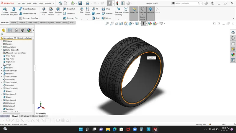
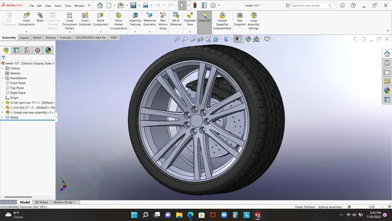
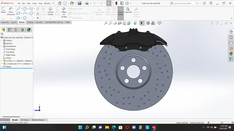
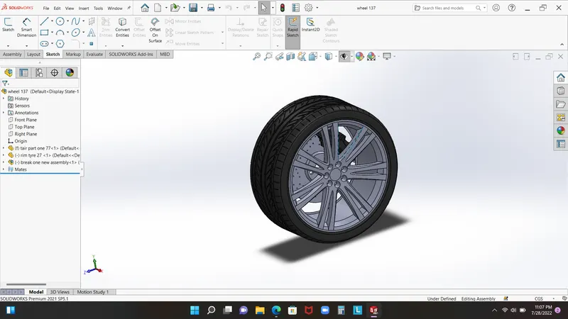
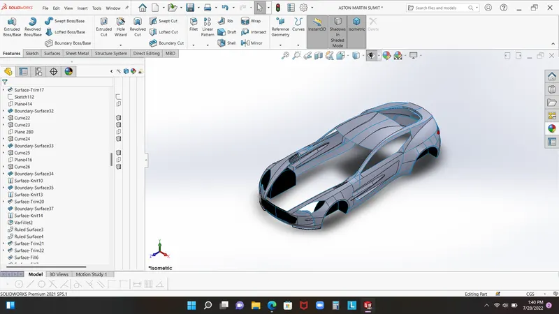
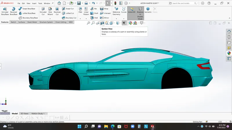
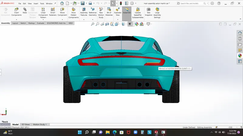
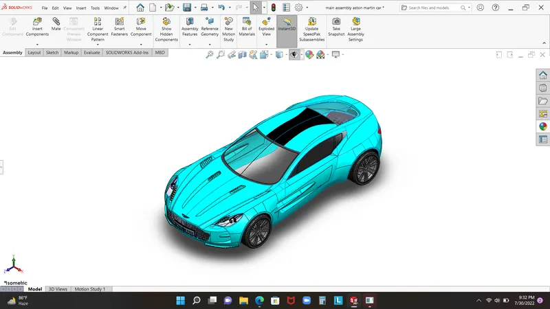
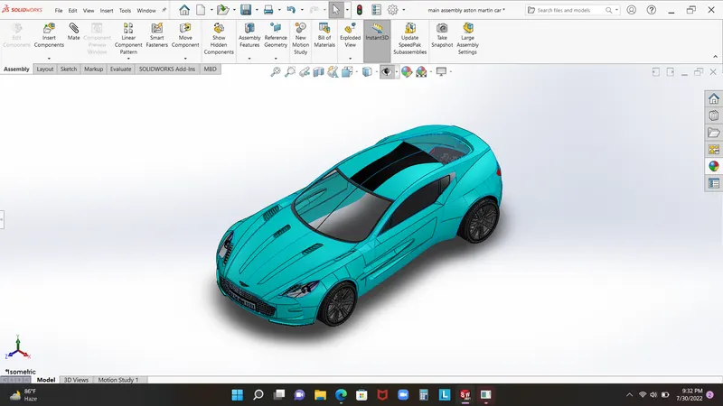
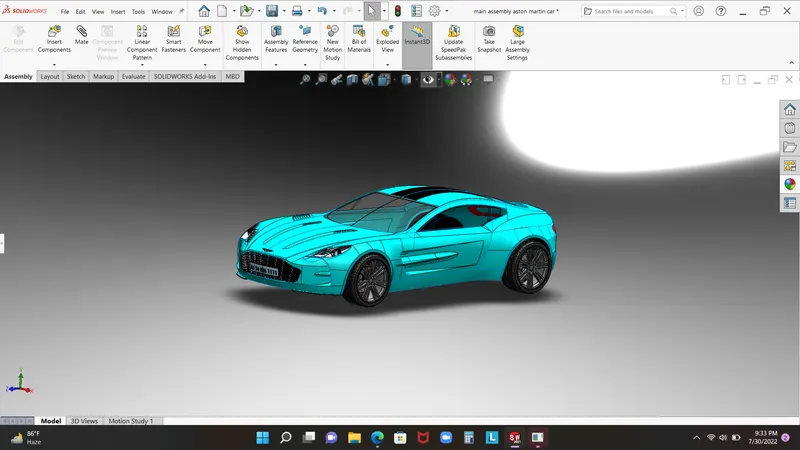
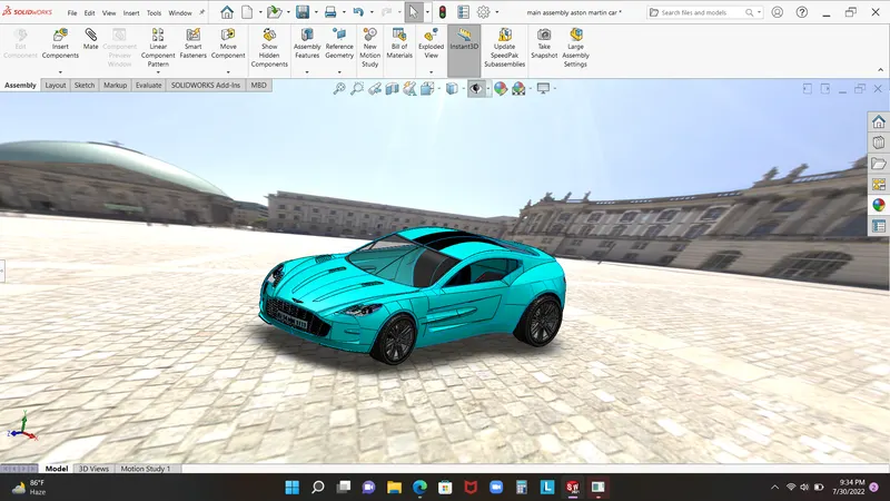
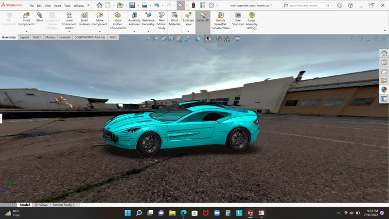
conclusion:- the solid works give us opportunity to lear about solidworks features in surface modeling and solid modeling. in this project user learn about part modeling and boundary surface which is trune into part surface. also we learn in this project about assembly and verious type of mate which used in assembley