Photo Realistic Rendering
Modelling and Assembling of American Chopper
Objective
- To create and model all the different parts of an American Chopper using Solidworks.
- To assemble all the created parts to complete the Chopper.
- To create a photorealistic Render of the Chopper using Solidworks Photoview 360.
Introduction
A chopper is a type of custom motorcycle which emerged in California in the late 1950s. The chopper is perhaps the most extreme of all custom styles, often using radically modified steering angles and lengthened forks for a stretched-out appearance. They can be built from an original motorcycle which is modified ("chopped") or built from scratch. Some of the characteristic features of choppers are long front ends with extended forks often coupled with an increased rake angle, hard tail frames (frames without rear suspension), very tall "ape hanger" or very short "drag" handlebars, lengthened or stretched frames, and larger than stock front wheels.
Part Modelling
The modelling in which each part of a complex body is first modelled separately so that it can be assembled to form that complex body is called part modelling.
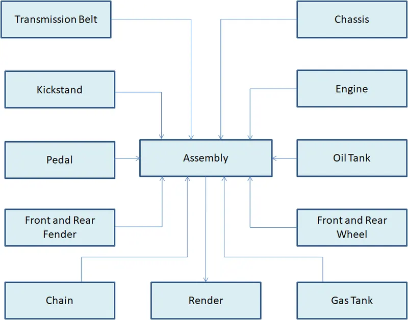
Parts to be modelled for American Chopper:
- Transmission Belt
- Kick Stand
- Front Fender
- Rear Fender
- Oil Tank
- Chain
- Pedal
- Front Wheel
- Rear Wheel
- Front Fork
- Chassis
- Engine
- Gas Tank
Design Methodology:
- Transmission Belt:
The function of the transmission belt is to transfer the power generated from the engine to the gear box.
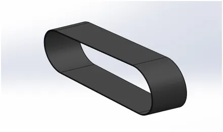
Features used to create Transmission Belt:
- Sketch
- Offset Entities
- Extrude Bose
- Fillet
Sketch:
It is a 2D representation of a particular model from different views such as front view, side view, top view, etc.
Offset Entities:
It is used to create the same sketch as the selected entities but at a certain required distance.
Extrude Boss:
This feature is used to convert a closed 2D sketch to a 3D model while adding material to it.
Fillet:
The fillet is used to round off faces or sharp edges in the interior or exterior corners of the part.
Appearances:
It is used to create visual effects by applying colour/ texture/decals to the selected face or body or to the complete part.
2.Kickstand:
It is a metal rod attached to a two-wheeler, lying horizontally when not in use, that may be kicked down into a vertical position to support the vehicle when it is not being ridden.
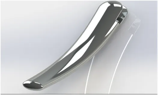
Features used to create Kickstand:
- Sketch
- Loft
- Dome
- Extrude Boss
- Extrude Cut
- Fillet
- Split
- Appearances
Loft:
The loft allows you to generate complex geometry in a single feature by interpolating surfaces between various cross-sections of a model which can be sketches, faces, or edges.
Dome:
It is used to create hemispherical structure which has been evolved from the arch and which usually forms a ceiling or roof over the selected surface/face.
Extrude Cut:
Extrude cut is a similar feature to extrude but instead of adding material it removes unwanted material from body based on the sketch.
Split:
Split is used to split a single face/surface into multiple faces/surfaces based on the sketch.
3.Front Fender:
The Front Fender is a part mounted on the fork above the front wheel to protect the rider and other parts of the chopper from debris, foreign particles, mud and sand kicked up from dirty puddles and rivulets.
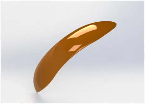
Features used to create Front Fender:
- Sketch
- Offset Entities
- Trim entities
- Revolve
- Dynamic mirror
- Split
- Appearances
Trim:
Trim is used to remove unwanted sketch entities or extra portions of the sketch based on some reference points/edges.
Revolve:
Revolve is used to create a revolved 3D model with reference of the sketch profile and axis of rotation.
Dynamic Mirror:
After creating a sketch on one side of the centreline, the Dynamic Mirror tool helps to create a symmetrical shape on the other side, which has the same relations as the created sketch.
4.Rear Fender:
The purpose of the rear fender is the same as the front fender. The only difference between them is rear fender is mounted above the rear wheel.
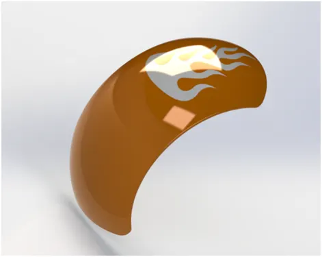
Features used to create Rear Fender:
- Sketch
- Offset Entities
- Trim Entities
- Revolve
- Shell
- Appearances
Shell:
Shell is used to convert solid bodies into hollow ones and creates thin-walled features on the remaining faces. If none of the faces is selected, shell hollows a complete solid part, creating a closed hollow model.
5.Chain:
Chain along with sprocket helps in transmitting power to the rear wheel. Properly lubricated chains can reach an efficiency of 98% or greater in the transmission. Unlubricated chains will significantly decrease performance and increase chain and sprocket wear.
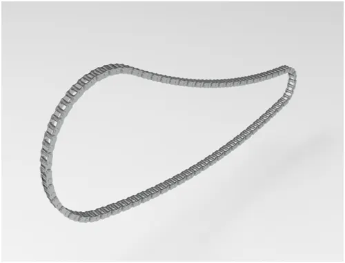
Features used to create Chain:
- Sketch
- Trim
- Fillet
- Extrude
- Curve Driven Pattern
Curve Driven Pattern:
It is used to repeat the selected function along the curve created through sketch.
6.Oil Tank:
The oil tank is used as a reservoir to meet the oil requirements of the engine from where it is pumped to other parts to lubricate them.
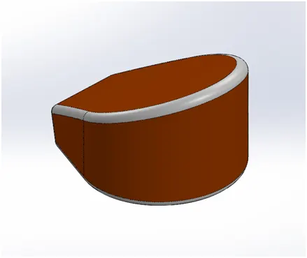
Features used to create Oil Tank:
- Sketch
- Extrude Boss
- Combine
- Fillet
- Shell
- Appearances
Combine:
A combine feature is used to merge two or more solids into a single solid.
7.Pedal:
The pedal is an extended piece from the chassis which is used for resting feet to maintain balance and comfort while riding the two-wheeler vehicle.
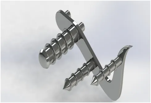
Features used to create Pedal:
- Sketch
- Extrude
- Fillet
- Linear pattern
- Dome
- Chamfer
- Appearances
Chamfer:
The chamfer is a cut on the edge or corner of any part that gives it slight slope rather than being perfectly square or rectangle.
Linear Pattern:
Linear Pattern is used to create a similar sketch linearly i.e. along a specified line.
8.Front Wheel:
It is the wheel which is located at the front of the vehicle and is used for the movement of vehicle along with the rear wheel. It consists of Rim, Brake Calliper and Rubber Tire.
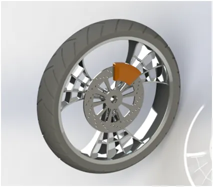
Features used to create Front Wheel:
- Sketch
- Revolve
- Trim Entities
- Fillet
- Extrude Boss/Base
- Revolve Cut
- Linear pattern
- Chamfer
- Cut Extrude
- Circular Pattern
- Appearances
Revolve Cut:
Revolved cut feature is similar to the revolve feature but instead of adding, it is used to remove solid geometry by revolving the sketch profile along a reference axis from the selected solid body.
Circular Pattern:
A circular pattern is used to create a similar sketch in a circular direction with respect to the reference axis of rotation up to user-defined instances.
9.Rear Wheel:
It is the wheel which is located at the rear end of the vehicle and helps in the movement of vehicle along with the font wheel. It also consists of Rim, Brake Calliper and Rubber Tire.
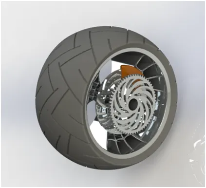
Features used to create Rear Wheel:
- Sketch
- Revolve
- Trim Entities
- Fillet
- Extrude Boss/Base
- Revolve Cut
- Linear pattern
- Chamfer
- Cut Extrude
- Circular Pattern
- Appearances
10.Front Fork:
The forks can be most easily understood as simply large hydraulic shock absorbers with internal coil springs. They allow the front wheel to react to imperfections in the road while isolating the rest of the motorcycle from that motion.
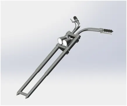
Features used to create Front Fork:
- Sketch
- Extrude
- Trim
- Revolve
- Split
- Move/copy Body
- Dome
- Mirror
- Combine
- Curve (Projected Curve)
- Sweep
- Appearance
Move/copy Body:
It is used to move/copy the body from one place to another.
Mirror:
Mirror is the feature used for creating similar body or edges with respect to some face/plane. Mirrored bodies can be used whether in a single or multi-body part and allows you to select solid geometry instead of the features and faces in a body.
Curve (Projected Curve):
The projected curve is used to create a 3D curve which is the projection of two different curves in which can be in different or same planes.
Sweep:
Sweep is used to create solid a shape by moving a 2D sketch Profile along a 2D or 3D sketch Path.
11.Chassis:
A chassis or frame forms the skeleton of all vehicles. It is the main support structure of the vehicle which bears all the stresses on the vehicle in both static and dynamic conditions. All the components like suspension, wheels, fuel tank, seats, handlebars, etc, are attached to this base structure which gives the vehicle its strength and ability to handle well on roads as well as paths with no proper roads.
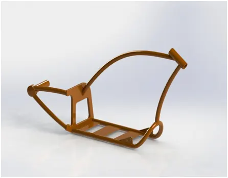
Features used to create Chassis:
- Sketch
- Offset entities
- Projected Curve
- Trim
- Sweep
- Split
- Revolve
- Cut Extrude
- Fillet
- Combine
- Appearance
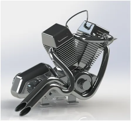
12.Engine:
The engine is the power generator in all vehicles. It creates power by converting chemical energy of fuel into the heat energy and then that heat energy is converted into mechanical work i.e. engine’s rotational motion. This rotation is transferred to the wheel with the use of the chain and sprocket through the gearbox and clutch.
Features used to create Engine:
- Sketch
- Convert Entities
- Trim
- Revolve
- Boss Extrude
- Cut Extrude
- Offset
- Dome
- Projected Curve
- Composite Curve
- Sweep
- Mirror
- Circular Pattern
- Fillet
- Split
Composite Curve:
It is used to create a combination of two curves in the same plane.
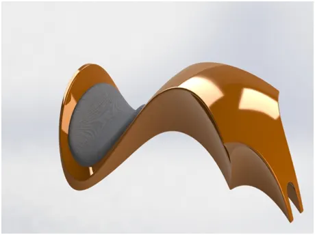
13.Gas Tank:
It is the reservoir of gas or fuel from where the fuel is pumped or given to the engine.
Features used to create Gas Tank:
- Sketch
- Trim
- Projected curve
- Sweep Surface
- Loft Surface
- Fill Surface
- Surface Trim
- Surface Knit
- Sweep Cut
- Fillet
- Appearances
Loft Surface:
Loft Surfaces are surfaces generated by multiple 3D Curves or existing edges creating a smooth tangency between the selected curves.
Fill Surface:
The Filled Surface feature constructs a surface patch with any number of sides, within a boundary defined by edges, sketches, or curves.
Surface Knit:
Surface knit is used to knit the two free edges/open edges of the surfaces together. Also, it reduces the gap between the two edges of the surface.
Sweep Cut:
It is used to cut a solid geometry by sweeping a closed profile along a closed or open path.
Assembly of American Chopper
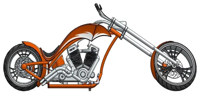
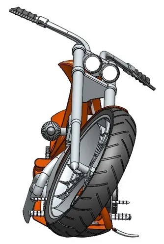
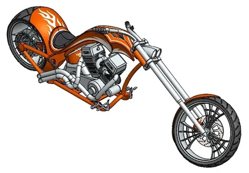
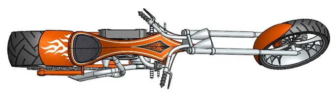
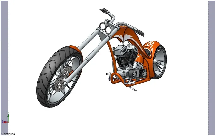
The chopper assembly is done in the assembly environment where all the parts which were modelled are imported to the assembly environments which are fixed one by one with the help of suitable mates to get the final assembly of the chopper.
Front View:
Side View:
Isometric View:
Top View:
Camera Setup:
Features used to create Assembly:
Insert Component:
It is used to insert all the parts modelled separately so that they can be assembled to create the final model
Mate:
Mates are used to create the relation between two mating parts that can be parallel, concentric, perpendicular, angular, etc. With respect to the fixed part, all the other parts can be mated. After defining the mates, the relative motions i.e., angular, linear movement between the mating parts are defined.
Rendering:
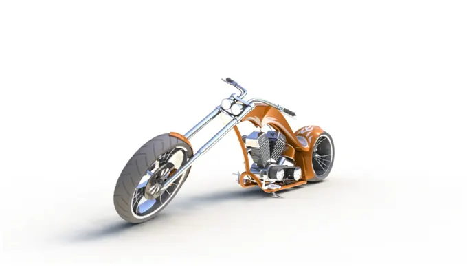
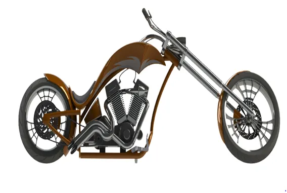
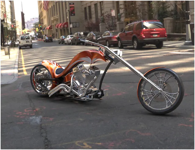
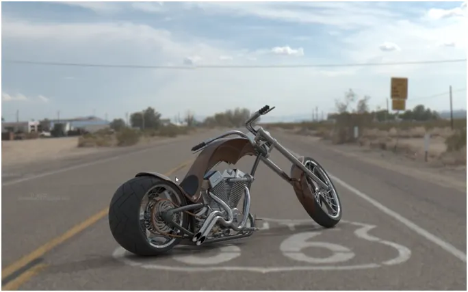
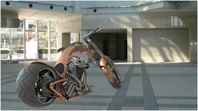
It is the process of generating photorealistic image of a 2D or 3D model by means of computer programs. In Solidworks, rendering is done by Photoview 360 and Solidworks Visualize.
Conclusion:
- All the parts of the chopper are modelled and assembled together successfully using Solidworks.
- The assembled chopper is rendered using Photoview 360 and Solidworks Visualize.