Radar Mast & Final Assembly of Yacht
MODELLING AND ASSEMBLING OF SUNSEEKER PREDATOR YACHT
Objective:
- To create and model all the different parts of Sunseeker Predator Yacht using Solidworks.
- To assemble all the modelled parts to complete the Yacht.
- To create a photorealistic Render of the Yacht using Solidworks Photoview 360.
Introduction:
Yacht, a sail or power-driven vessel is usually light and comparatively small and is used for racing or for recreation. In recreation, the term applies to very large craft, originally powered by sail and later by steam or internal-combustion engines. Until the 1950s, almost all yachts were made of wood or steel, but a much wider range of materials is used today. Although wood hulls are still in production, the most common construction material is fiberglass, followed by aluminum, steel, and carbon fiber. Apart from materials like carbon fiber and aramid fiber, spruce veneers laminated with epoxy resins have the best weight-to-strength ratios of all boatbuilding material.
Part Modelling:
It is a process of creating a virtual prototype of an object or any component by modelling each part separately through different sketch tools and 3D tools to help attain the required part in graphical form.
Surface Modelling:
Surface modelling is a method of creating planar or non-planar complex geometry which has zero thickness. The zero thickness geometry is known as surface. The surfaces are generally used to create models of complex shapes. Surface models can also be converted into solid models.
Parts to be modelled:
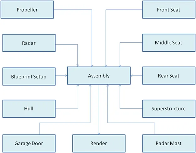
- Propeller
- Radar
- Blueprint Setup
- Hull
- Garage Door
- Front Seat
- Middle Seat
- Rear Seat
- Superstructure
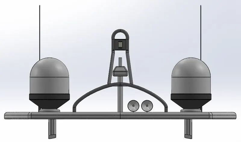
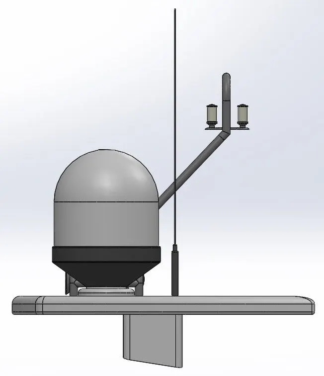
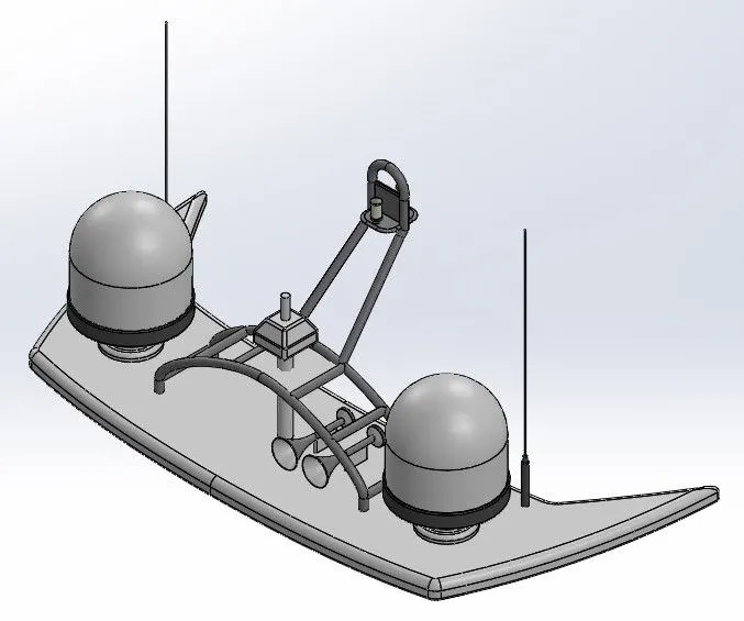
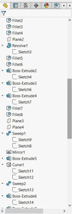
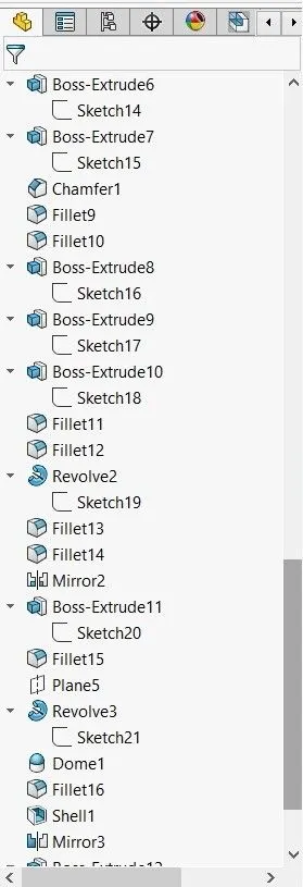
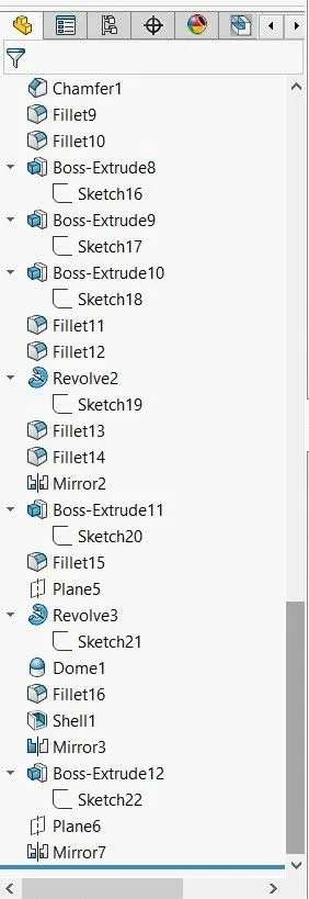
- Radar Mast
Design Methodology:
- Propeller:
A propeller is the most important part of the ship without which a ship can't move. So, the main function of propeller is to propel the ship. It is a rotating fan like structure which is used to propel the ship by using the power generated by the main engine of the ship. This generated power produces a thrust which imparts momentum in the water, resulting in a force that acts on the ship and helps the ship to move in forward or backward direction.
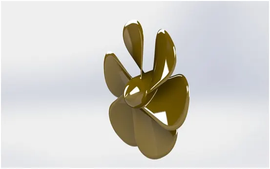
Commands used to model Propeller
- Spline
- Circle
- Line
- Revolved Boss/Base
- Lofted Boss/Base
- Extruded Cut
- Reference Plane
- Circular Pattern
- Fillet
- Appearance
Spline:
It is a 2D or 3D curve which is defined by a set of control points & handles and is used to create complex sketches/surfaces.
Circle:
It is used to create circular paths by giving desired dimensions.
Line:
It is one of the most important tools in 2D sketching as it can be drawn horizontally, vertically or at any specified angle.
Revolved Boss/Base:
Revolve is used to create a revolved model with reference to the sketch profile and axis of rotation.
Lofted Boss/Base:
The loft allows you to generate complex geometry in a single feature by interpolating surfaces between various cross-sections of a model by specifying start and end constraints and adding guide curves to control the path shape.
Extruded Cut:
It is used to remove unwanted material from body in a specified direction based on the sketch.
Reference Plane:
These are the planes created to draw a sketch at a particular place or to create a sectional view of a model.
Circular Pattern:
A circular pattern is used to create a similar sketch in a circular direction with respect to the reference axis of rotation up to user-defined instances.
Fillet:
It is used to round of the internal or external edges of a surface/sketch.
Appearance:
It is used to create visual effects by applying colour/ texture/decals to the selected face or body or to the complete part.
- Radar:
A Radar is a very important part of any ship or boat as it is used to in detecting other ships or landmasses or any other obstacle even if the visibility is less than usual.
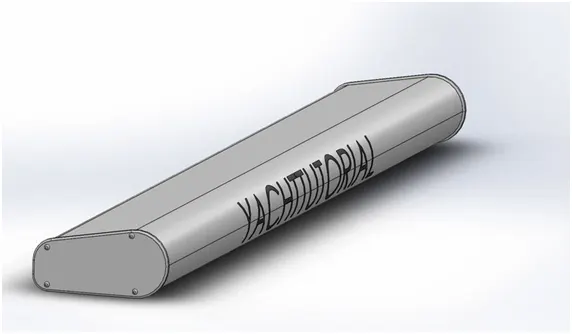
Commands used to model Radar
- Line
- Circle
- Extruded Boss/Base
- Extruded Cut
- Fillet
- Text
- Mirror
- Split Line
- Appearance
Extruded Boss/Base:
This feature is used to convert a closed 2D sketch to a 3D model while adding material to it in the third direction.
Text:
It is used to insert text in the model wherever required.
Mirror:
It creates a copy of a selected feature, mirrored about a plane or line or face.
Split Line:
Split Line is used to split a single face/surface into multiple faces/surfaces based on the sketch.
- Blueprint Setup:
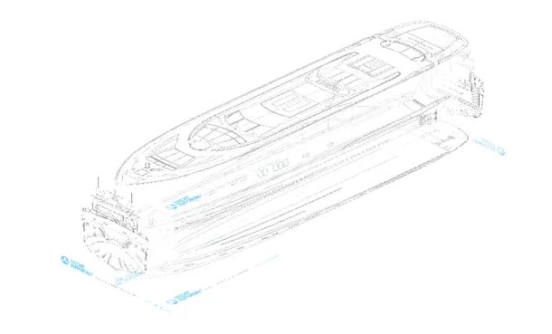
A Blueprint is a photographic detailed plan or drawing on light sensitive sheets. These are easy to read and make faster to make. Below is the Blueprint used to model the Yacht:
- Hull:
A hull is the watertight body of a ship, boat, or flying boat. The hull may open at the top (such as a dinghy), or it may be fully or partially covered with a deck. The line where the hull meets the water surface is called the waterline.
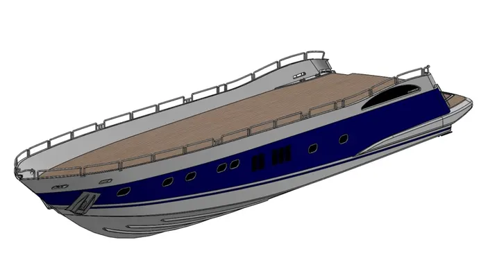
Commands used to model Hull:
- Line
- Spline
- Circle
- Rectangle
- Arc
- Slot
- 3D Sketch
- Extruded Surface
- Revolved Surface
- Lofted Surface
- Surface Trim
- Surface Fill
- Surface Knit
- Delete Face
- Projected Curve
- Chamfer
- Fillet
- Reference Plane
- Split
- Extrude Boss/Base
- Extruded Cut
- Mirror
- Appearance
Rectangle:
It is used to create a rectangle or square at any specified angle.
Arc:
It is a shape of a part of circle which can be a tangent arc, 3 point arc and center point arc.
Slot:
It is a long, narrow aperture or slit in a machine for something to be inserted.
3D Sketch:
It simply means creating a sketch along X, Y and Z direction.
Extruded Surface:
It is used to extrude any contour or any sketch in one or more than one direction.
Revolved Surface:
A surface created by revolving any contour or any sketch around an axis is called revolved surface.
Lofted Surface:
It creates a lofted surface between two or more profiles or sketches. Specify start and end constraints and add guide curves to control the path shape.
Surface Trim:
It is used to trim the unwanted surface usually at the intersection of two or more surfaces.
Surface Fill:
It creates a surface within a specific boundary which can be defined by sketch or curve.
Surface Knit:
It is used to join or combine two or more surfaces into a single one so that a solid body can be created.
Delete Face:
It is used to delete an unwanted face of a body or a surface.
Projected Curve:
The projected curve is used to create a 3D curve which is the projection of two different curves in which can be in different or same planes.
Chamfer:
The chamfer is a cut on the edge or corner of any part that gives it slight slope rather than being perfectly square or rectangle.
- Garage Door:
A garage door is a large door on a garage that opens either manually or by an electric motor (a garage door opener) which are generally used to accommodate automobiles or other vehicles.
Commands used to model Garage Door
- Line
- Spline
- Circle
- Text
- Extruded Cut
- Reference Plane
- Shell
- Fillet
- Mirror
- Appearance
Text:
It is used to insert text in the model wherever required.
Shell:
Shell is used to convert solid bodies into hollow ones and creates thin-walled features on the remaining faces. If none of the faces is selected, shell hollows a complete solid part, creating a closed hollow model.
- Front Seat:
These are two interconnected seats that are built back to back with each other and are located at the front of the superstructure.
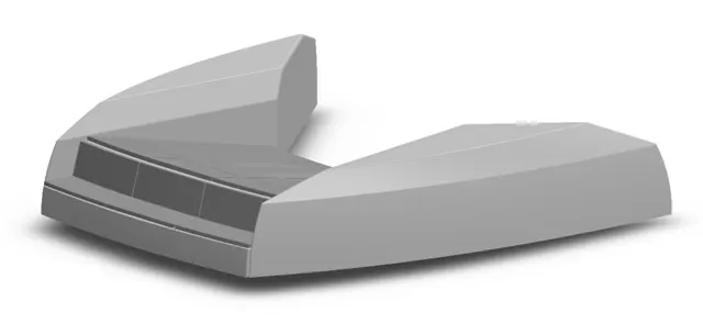
Commands used to model Front Seat
- Sketch
- Line
- Spline
- Circle
- Arc
- Extruded Cut
- Revolved Boss/Base
- Extruded Surface
- Lofted Surface
- Trim Surface
- Filled Surface
- Knit Surface
- Swept Surface
- Revolved Surface
- Appearance
Swept Surface:
It is used to create a closed profile surface along an open or closed path and uses a tangent plane at the end of the path so that the path is normal to the swept surface.
- Middle Seat:
The middle seat is located just behind the superstructure and is provided with a luxury table to dine out or have a meeting or just to enjoy the view.
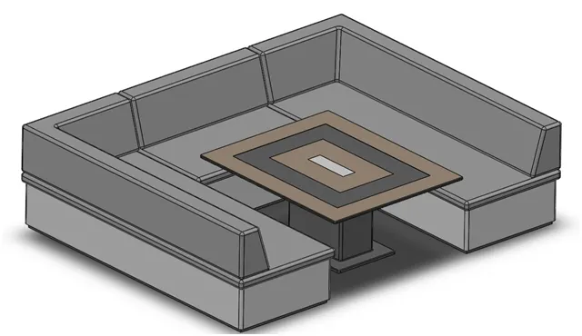
Commands used to model Middle Seat
- Sketch
- Line
- Rectangle
- Extruded Boss/Base
- Chamfer
- Fillet
- Mirror
- Reference Plane
- Appearances
- Rear Seat:
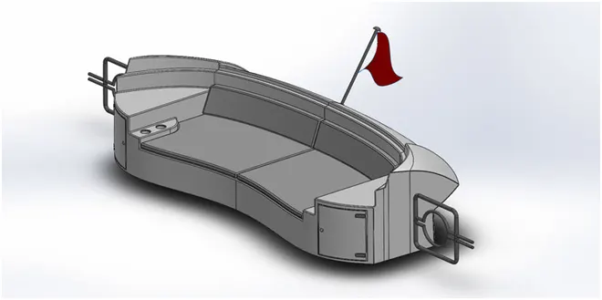
It is placed at the back end of the deck surface and has a flag placed behind the seat since it’s the end part of the yacht. Slots for cup or mug holder were also provided in case of enjoying the view from the rear seat.
Commands used to model Rear Seat
- Sketch
- Line
- Spline
- Circle
- Arc
- Rectangle
- Swept Surface
- Extruded Surface
- Offset Surface
- Filled Surface
- Knit Surface
- Ruled Surface
- Lofted Surface
- Reference Plane
- Extruded Boss/Base
- Revolved Boss/Base
- Fillet
- Mirror
- Appearance
- Superstructure:
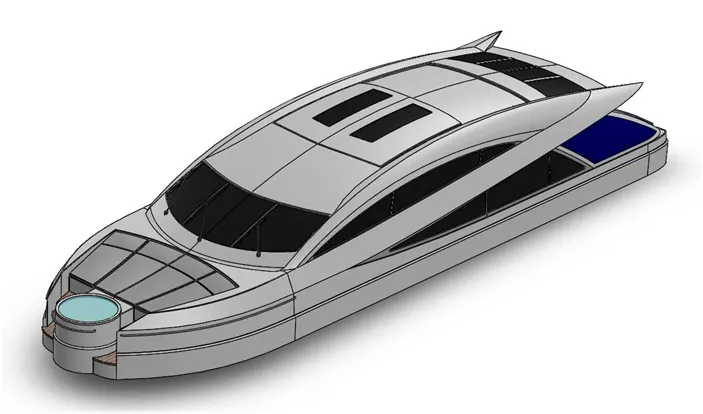
A superstructure is an upward extension of an existing structure above a baseline. This term is applied to various kinds of physical structures such as buildings, bridges, or ships.
Commands to create Superstructure
- Sketch
- Line
- Spline
- Circle
- Rectangle
- Arc
- Extrude Surface
- Swept Surface
- Ruled Surface
- Knit Surface
- Trim Surface
- Filled Surface
- Extend Surface
- Lofted Surface
- Revolved Surface
- Fillet
- Chamfer
- Projected Curve
- Reference Plane
- Split Line
- Radar Mast:
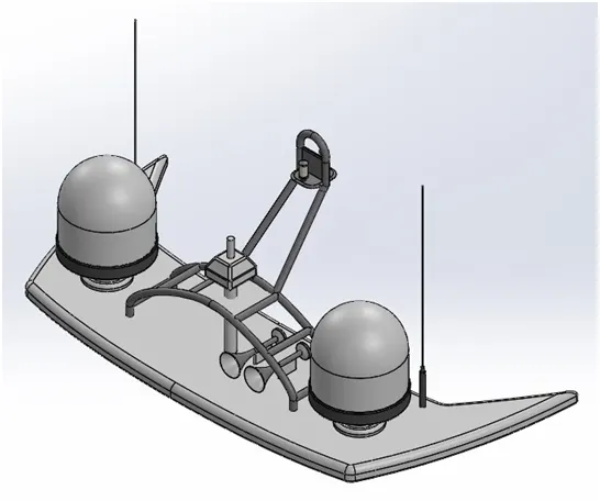
It is a vertical ship structure mounted on top of bridge and forward of the forecastle towards the ship’s bow and its function is to hold necessary equipment such as radar receiver, navigation lights, ships horn, flags and derricks in some case.
Commands used to model Radar Mast
- Sketch
- Line
- Spline
- Rectangle
- Arcs
- Extruded Boss/Base
- Lofted Boss/Base
- Revolved Boss/Base
- Swept Boss/Base
- Reference Plane
- Projected Curve
- Fillet
- Mirror
- Dome
- Shell
- Appearance
Assembly:
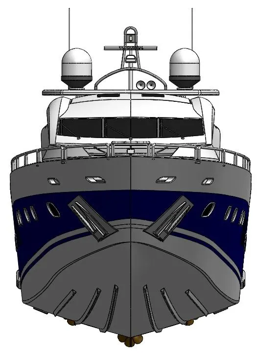
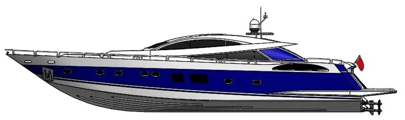
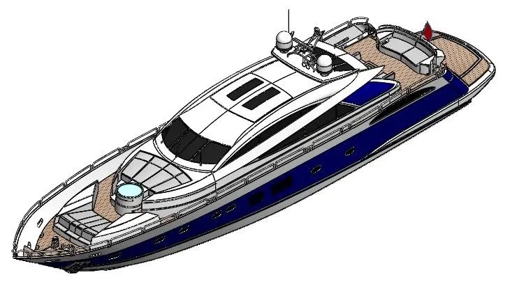
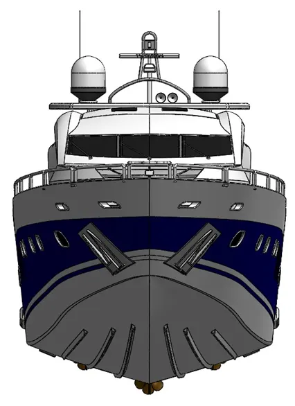
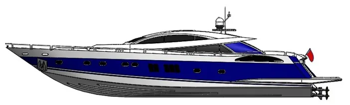
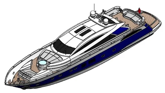
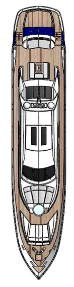
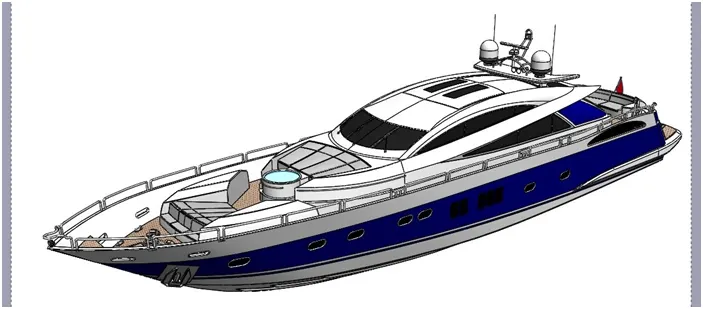
It is an environment where the separately modelled parts are imported and are fixed one by one with the help of suitable mates to get the final model of the yacht.
Front View:
Side View:
Isometric View:
Top View:
Camera Setup:
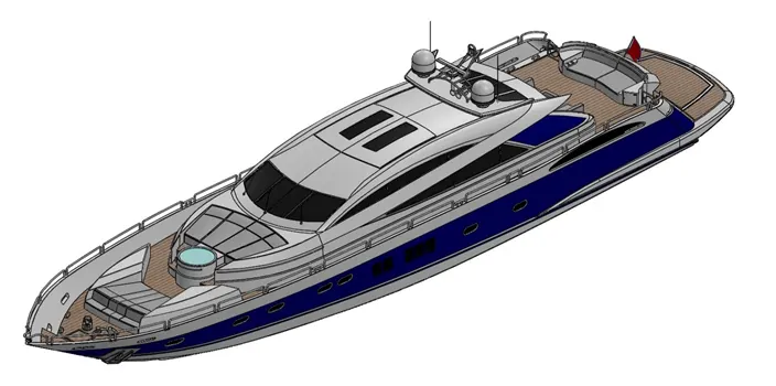
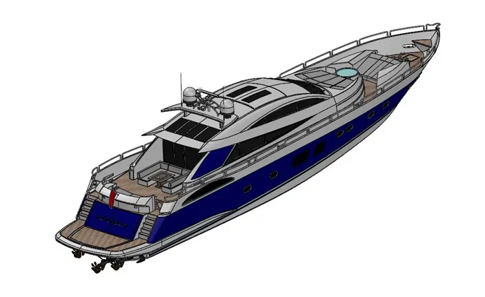
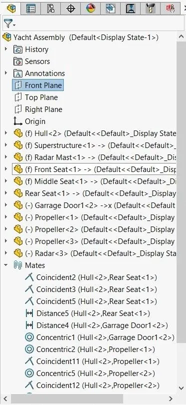
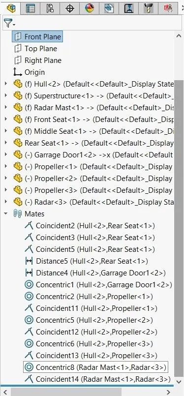
Commands used in Assembly
- Insert Component
- Mate
Insert Component:
It is used to insert all the parts modelled separately so that they can be assembled to create the final model.
Mate:
It is a geometric relationship used to create the relation between two mating parts that can be parallel, concentric, perpendicular, angular, etc. With respect to the fixed part, all the other parts can be mated. After defining the mates, the relative motions i.e., angular, linear movement between the mating parts are defined.
Rendering:
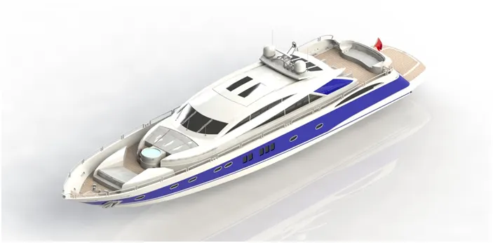
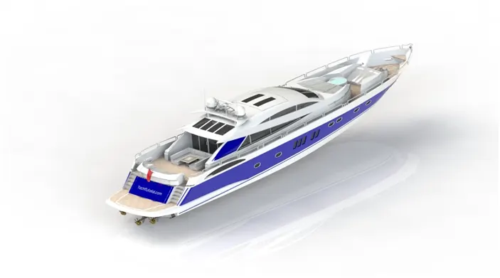
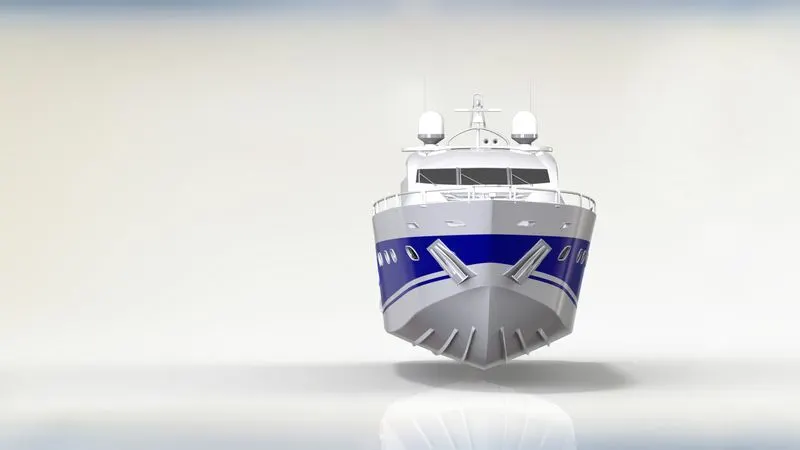
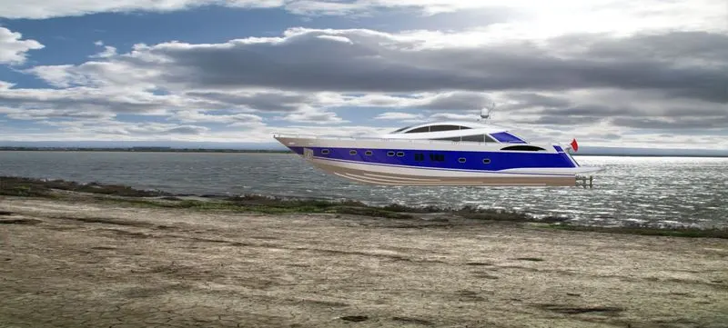
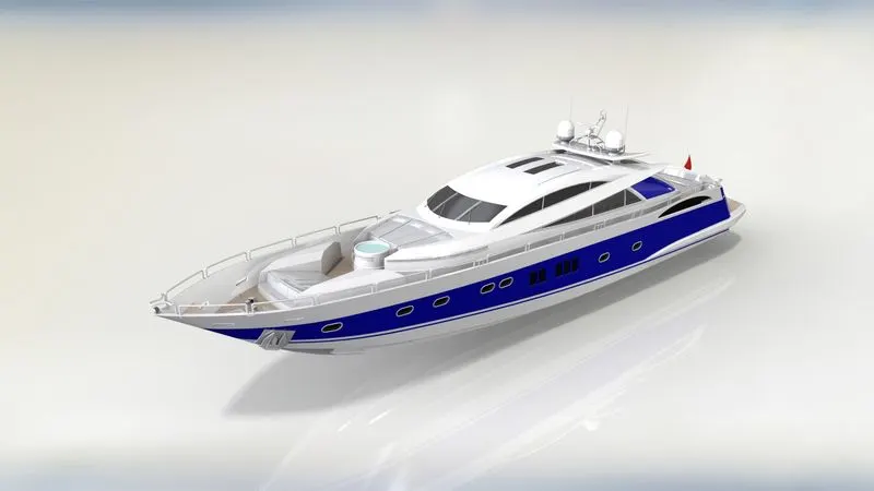
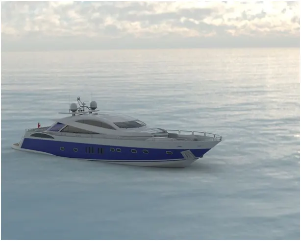
It is the process of generating photorealistic image of a 2D or 3D model by means of computer programs. In Solidworks, rendering is done using Photoview 360.
Conclusion:
- All the parts of the Sunseeker Yacht are modelled and assembled together successfully using Solidworks.
- The assembled Yacht is rendered using Photoview 360 and Solidworks Visualize.