DESIGN OF AMERICAN CHOPPER
INTRODUCTION
This report contains explanation of American chopper based on my experience by using SOLIDWORKS 2018.
OBJECTIVE
First and last objective understands the tools of solidworks after that proper dimension and appearance make a chopper to next level.
Steps involved
- Create individual parts of American chopper.
- Assembly them with proper mates.
- Rendering process by using photo view 360 and solidworks visualize.
EXPLANATION BEGIN
Let start with step one part modelling
American chopper contain 13 parts in my design there are
- Transmission belt
- Front fender
- Rear fender
- Kick stand
- Chain
- Oil tank
- Pedal
- Front wheel
- Fork
- Rear wheel
- Chassis
- Engine
- Gas tank
Let me explain the each parts which my part model
- Transmission belt
It uses to transmit the power between two shafts.
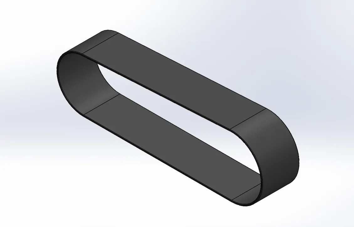
Features used boss extrude and fillet.
This belt create in front plane with 3.5 mm thickness and extude to convert in 3D form and I used fillet to give realistic look for this belt.
Note :
Always remember to make your sketch full defined to get better result.
- Front fender
It a cover plate from front wheel
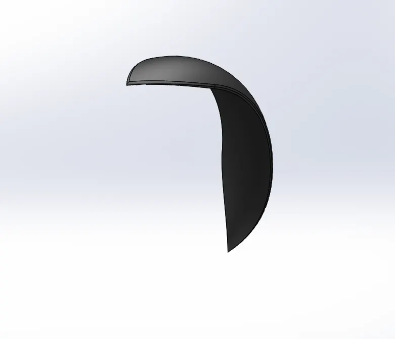
Features used revolve,split and fillet.
This part ceate in front plane by using 3 point arc and revolve into particular angle and creating another two sketch to split and remove a part to get desire design and fillet it to get realistic look.
- Rear fender
It a cover plate from rear wheel
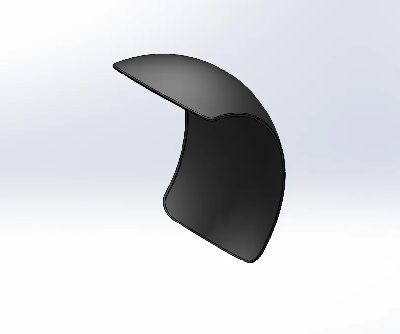
Features used revolve, split, fillet and shell.
A sketch create in front plane by using 3 point arc and offset to get thickness of fender and revolve it particular angle and create another sketch to split and remove part then fillet and shell to get realistic look.
- Kick stand
It used to stand a motorcycle in slight vertical position when motorcycle in stationary
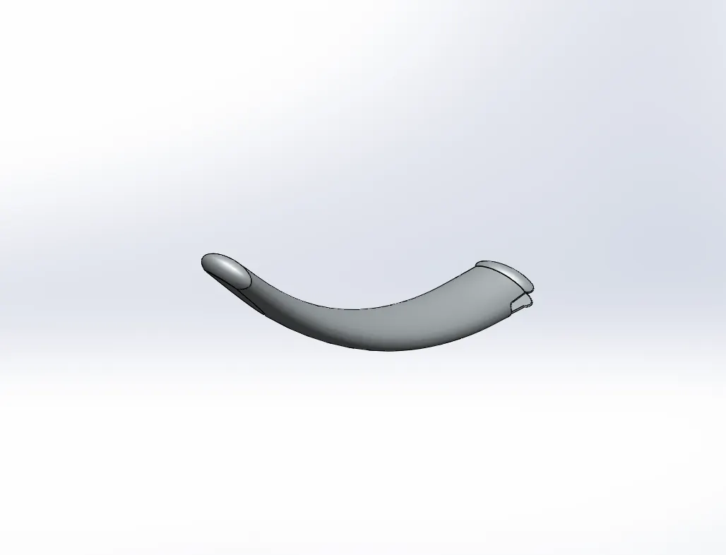
Features used loft, dome, extrude cut, split, boss extrude and fillet.
Loft is a feature to create a stand base look by ellipse sketch and guide line. To turn a flat face into round face dome feature is used at top and bottom. To create a mate part between kick and chassis cut extrude feature is used and another sketch create in top side then boss extrude it. Finally fillet to get realistic look.
- Chain
Its help to transmit the power between engine to rear wheel by the help of spocket.
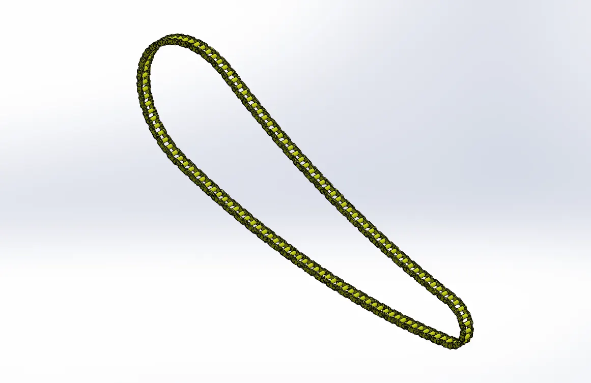
Features used boss extrude, linear pattern, circular pattern, fillet, mirror and combine.
The whole part create by using reference sketch in front plane. To reduce a work load block should be created. By the help of reference sketch block sholud placed then fillet and pattern. repeat it then get complete model then mirror and combine to get good look of chain.
- Oil tank
Oil tank is used in motorcycle to stored oil for better performance.
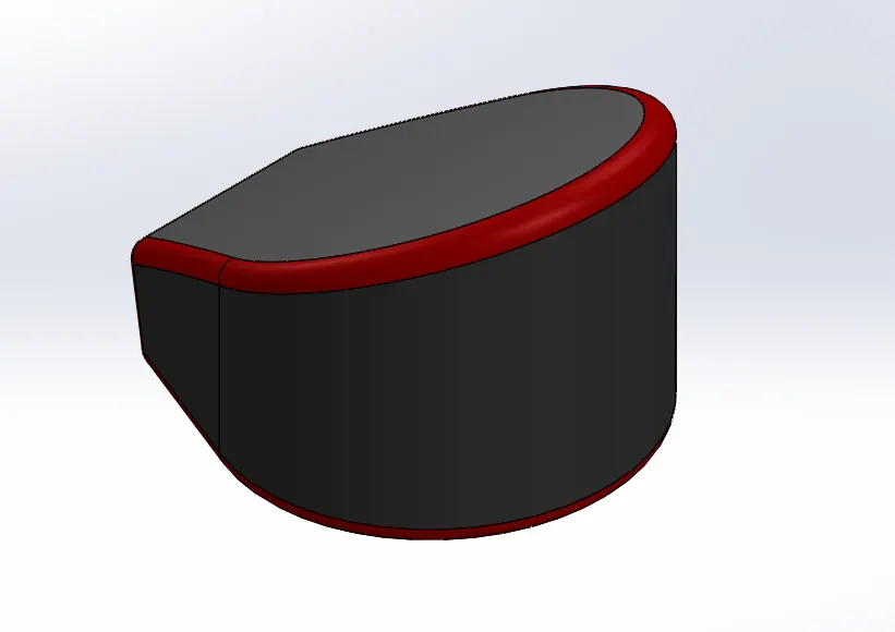
Features used boss extrude, combine, fillet and shell.
This part model create by combination of two sketch. Boss extrude and combine it to make one part then fillet and shell to get better look.
- Pedal
Its use to rest the foot in it to give confort for rider.
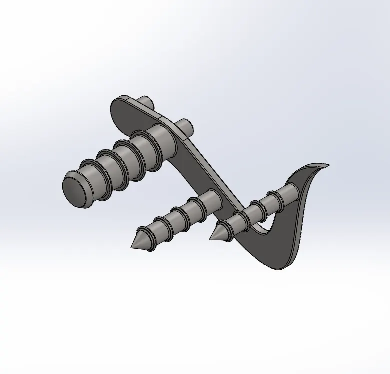
Features used boss extrude, fillet, revolve, dome, chamfer and pattern.
Iike every sketch model it create by given dimensions and features like boss extrude,fillet,revolve,dome,chamfer and linear pattern.
- Front wheel
It help vehicle to move forward and backward. It contains rim, rotor, caliper and tire.
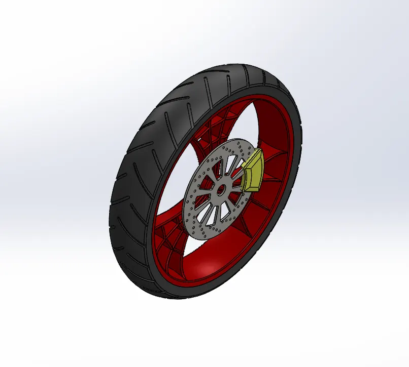
Features used revolve extrude, boss extrude, revolve cut, cut extrude, circular pattern, mirror, combine, chamfer and fillet.
Create a bass sketch to revolve it and sketch to make a rim by boss extrude and fillet. Sketch on face to create rotor and caliper then circular pattern to make holes in rotor. Chamfer and fillet for good look. Mirror and combine for create a desire model.
- Fork
It helps to balance and turn a wheel into desire direction. Its hold other control device for rider and shock absorber which is held by triple clamp.
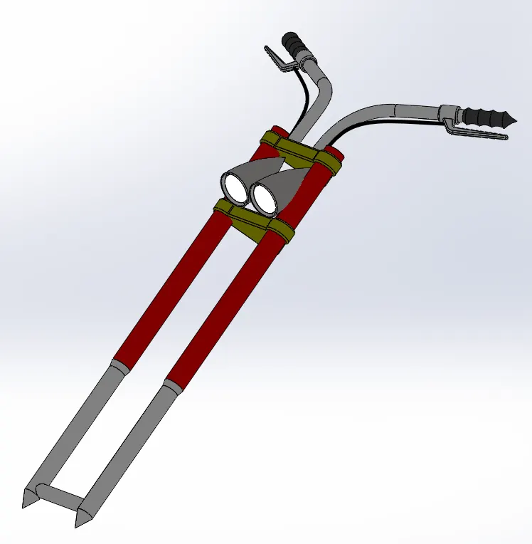
Features used boss extrude, revolve extrude, revolve cut, cut extrude, project curves, swept boss, combine, mirror, chamfer and fillet.
Create a long tube by given dimension then sketch on face to create clamp and project curve for create a handle bar swept and revolve detail design and mirror it. Combine to make it single part and apply appearance for better look.
- Rear wheel
It helps to move a bike forward by the power of engine. It contain rotor, rim, tyre, caliper, and sprocket.
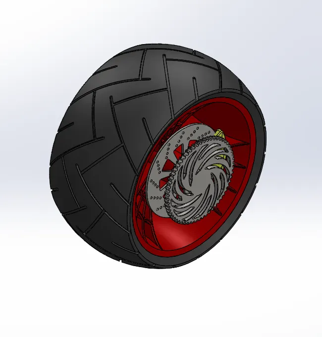
Features used revolve extrude, boss extrude, revolve cut, extrude cut, circular pattern, mirror, combine, chamfer and fillet.
Create a bass sketch to revolve it and sketch to make a rim by boss extrude and fillet. Sketch on face to create rotor and caliper then circular pattern to make holes in rotor. Another sketch on face to create sprocket by boss extrude and cut extrude and circular pattern. Chamfer and fillet for good look. Mirror and combine for create a desire model.
- Chassis
It is a skeleton of the motorcycle because it carry every part in the vehicle. It is a base for every vehicle.
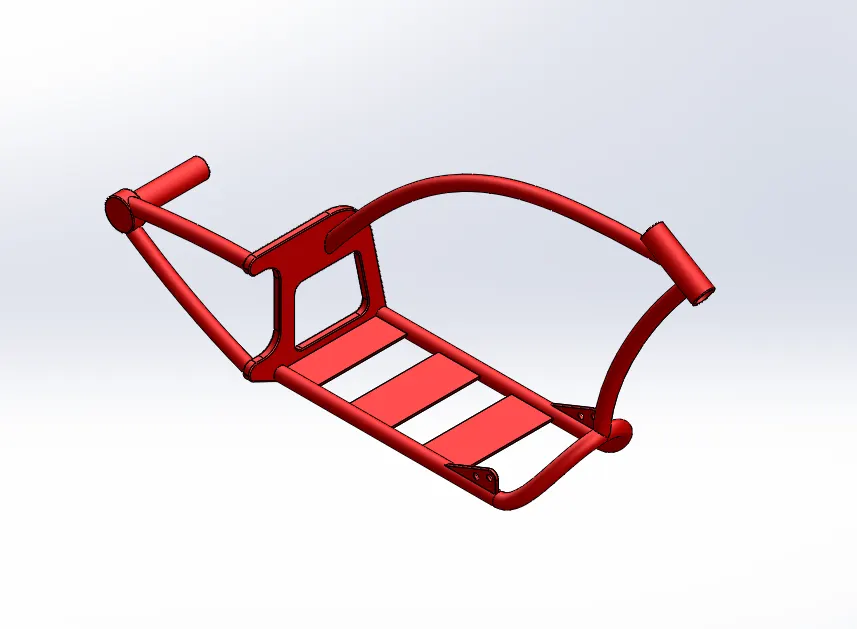
Features used revolve extrude, boss extrude, revolve cut, extrude cut, linear pattern, project curves mirror, combine, dome, chamfer and fillet.
- Engine
Engine is a main component of the vehicle. It’s give a power to move a bike without any external force.
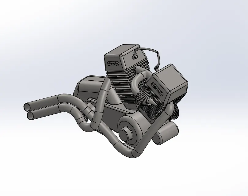
Features used revolve extrude, boss extrude, revolve cut, extrude cut, linear pattern, project curves mirror, combine, dome, chamfer and fillet.
It creates by the help of blueprint. By the reference we have then we can model and project it desired shape.
- Gas tank
It’s carry a fuel for the engine. Based on design fuel carry level is varies for different motorcycles.
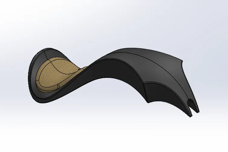
Features used swept surface, loft surface, boundary surface, project curve, knit surface, combine, shell, mirror and fillet.
It creates by the help of blueprint. By the reference we have then we can model and project it desired shape.
Assembly
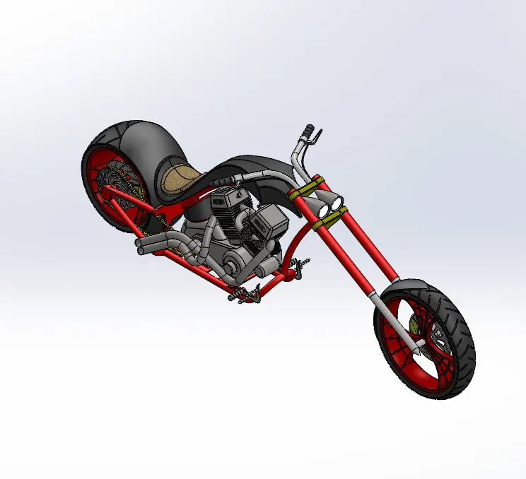
By opening every part model it bring single location to assemble a part easier. By using different type of mate operation such as concentric, coincident, parallel etc. mate will be made in that we face some overlapping issues but it resolve in assemble level itself. After resolve everything assemble will be done at our desires.
RENDERING
Rendering is a process to bring our model into realistic ways with environment.
There are two type of methods will be used such us
- Photo view 360
- solidworks visualize.
Photo view 360
It will be done in solidwoks 2018 itself. It help as to add light, camera, decal and scene.
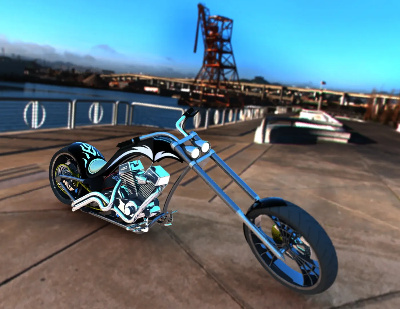
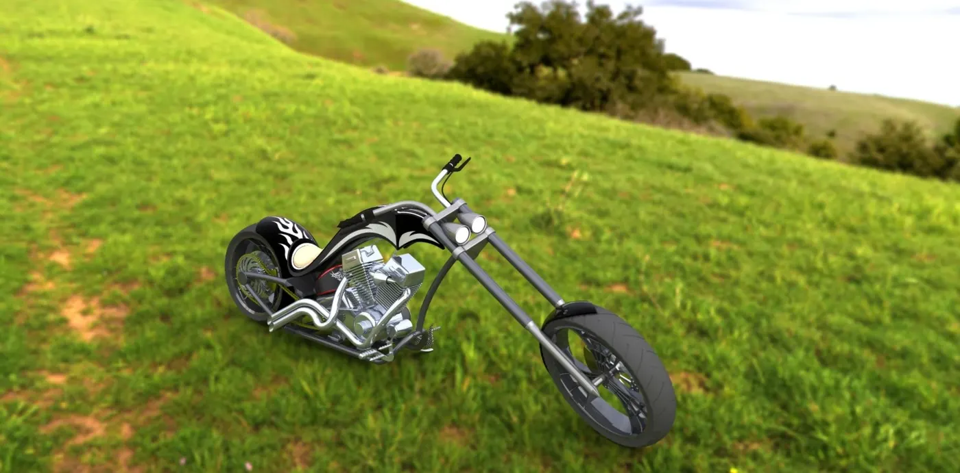
Solidworks visualize
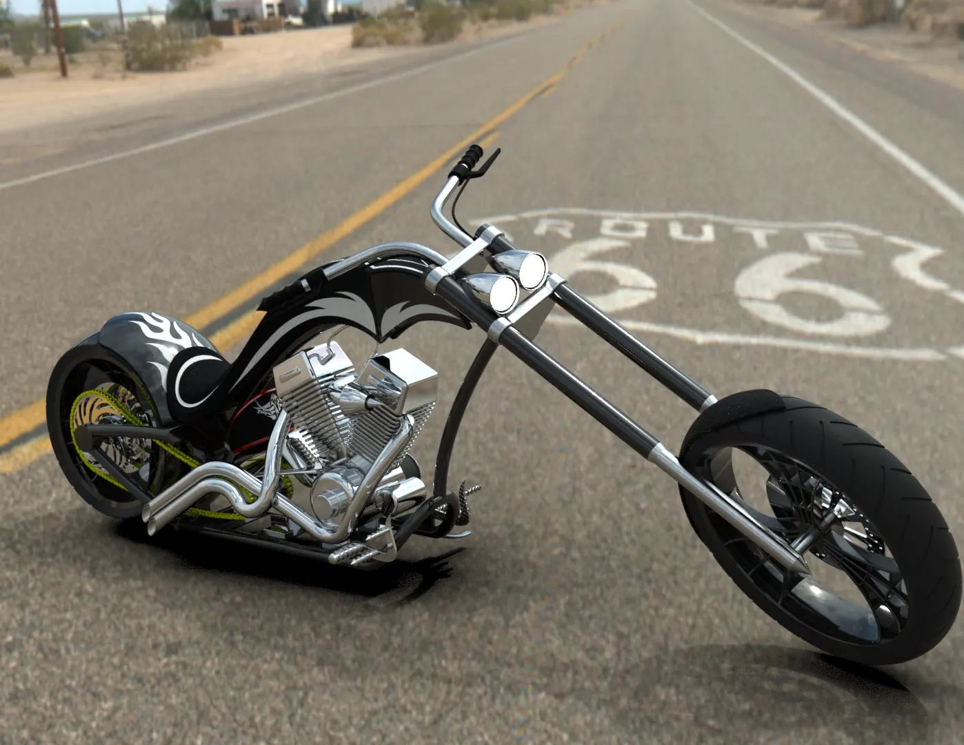
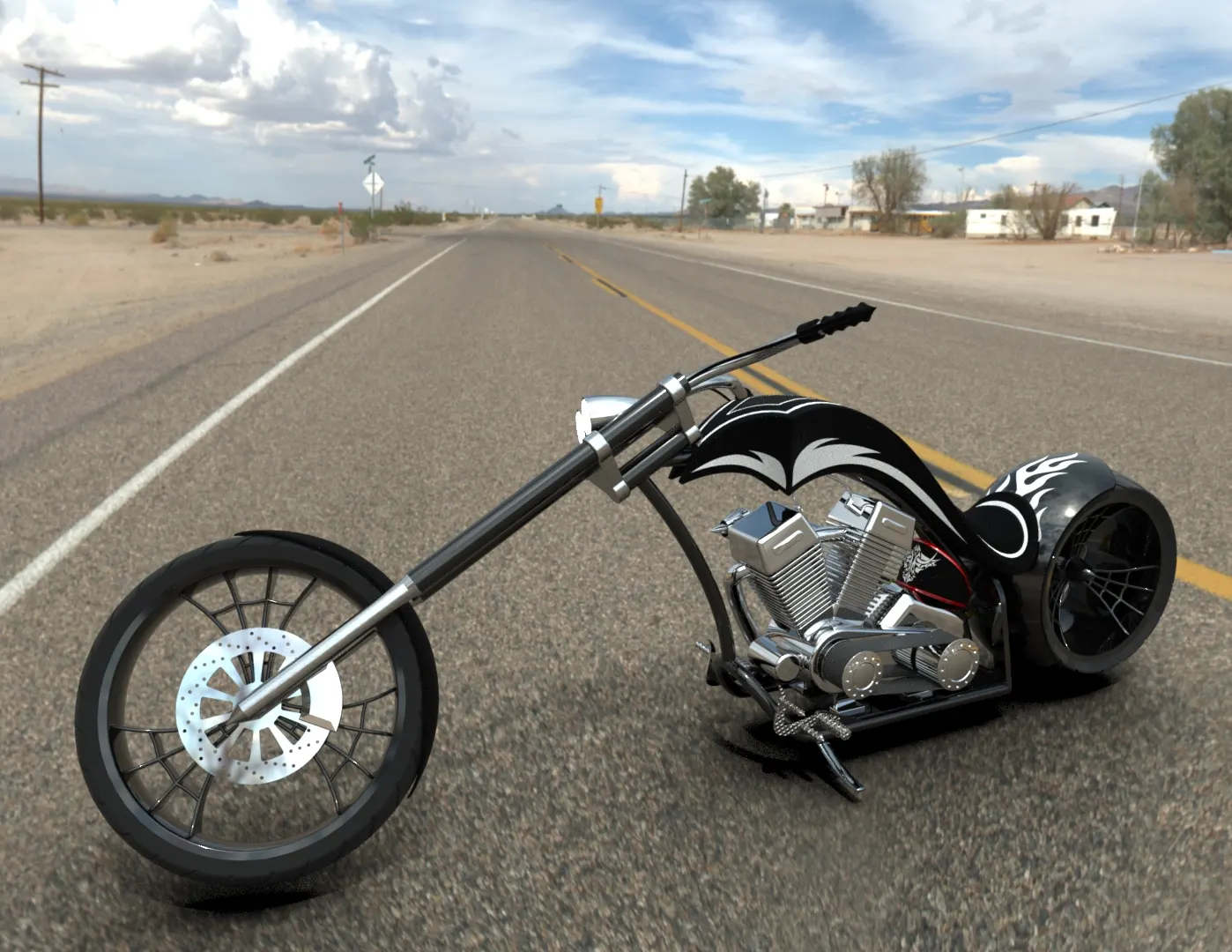
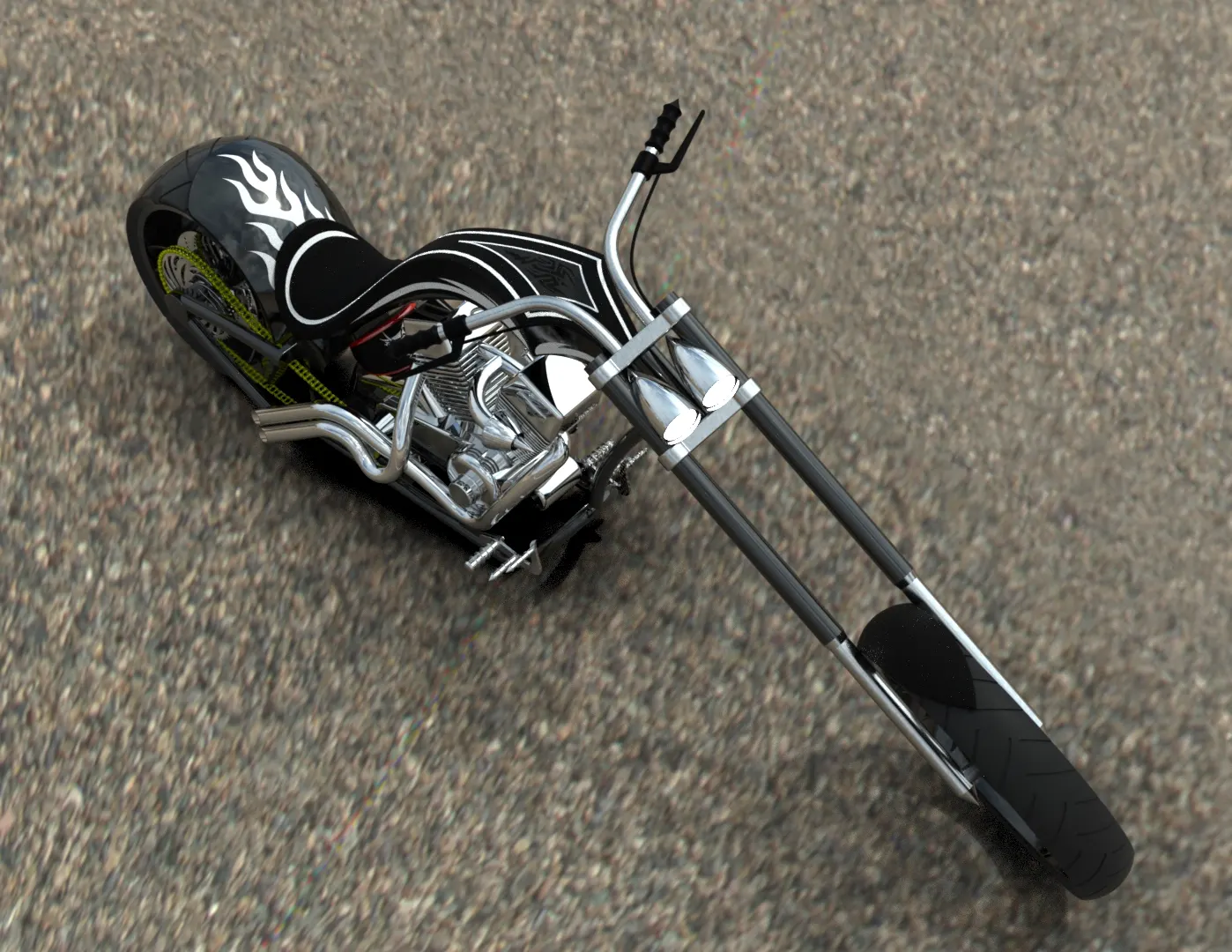
It another solidwork product it’s give a perfect render image then photo view 360 in my experience let me show some image
Conclusion
- The part model its design as per given dimensions.
- Assembly made with proper mate and resolve overlapping issues.
- Rendering process done both photo view 360 and solidworks visualize.