Advanced Sheet Metal Design Using NX Cad Challenge_2_Box Assembly
BOX ASSEMBLY IN NX ADVANCE SHEET METAL
MODELLING
OBJECTIVE:
To learn how to use fundamental function and model a box assembly in NX advances sheet metal modelling.
INTRODUCTION:
What you will see in this report was how I design and model a box assembly concept
Support by skill-lync.
DESIGN METHODOLOGY:
|
2D SKETCH & BASIC DIMENSIONS |
|
STEP BY STEP OF MODELING EACH BODY |
| FINAL VIEW OF BOX ASSEMBLY |
DESCRIPTION:
TOOL & FEATURE USED:
Tab – This feature use to create a base and secondary block. It’s a first step to do create casing.
Normal cut-out- It uses to remove a selected area and get desire cut-out.
Bend- This feature used to bend a tab to required length and angle.
Flange-one of coolest tool to use simplify a process and get required shape.
Break corner- It use to create a fillet in selected corner a required radius.
Unbend-This feature used to flat the model plane sheet metal it help us to make complex design.
Hole- It use to create a required hole in specified location.
Mirror-This feature used to mirror a shape according to mid plane.
Dimple- It use to create a complex shape in sheet metal.
Rebend-It use to rebend the bended sheet in reverse order.
Flat pattern- It uses to create a 2D view sketch from 3D modelling.
Hem - This command use to edge of a tab of body which has been turned under and sewn.
Bead - It is a command to lift material along the contour of a sketch that simulates a stamping tool.
Datum plane - This command use to create a plane at required place.
SCREENSHOTS OF BOX ASSEMBLY:
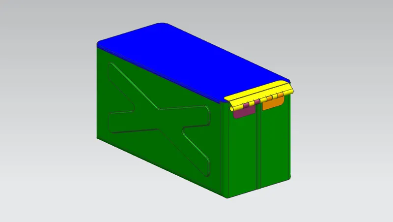
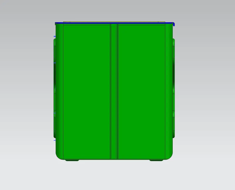
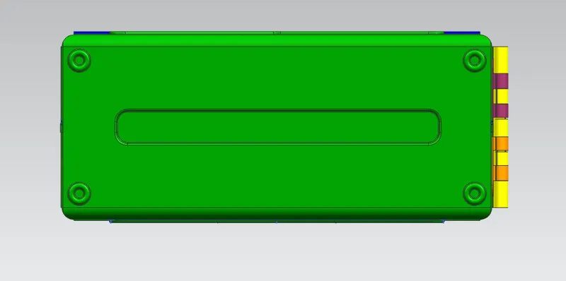
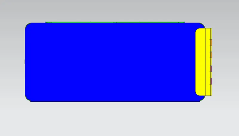
CONCLUSION:
Box assembly model create as per given data by using advance sheet metal design in NX-CAD.