Photo Realistic Rendering
MODELING OF AMERICAN CHOPPER IN SOLIDWORKS
OBJECTIVE:
To design a model of American Chopper using SolidWorks CAD software with basic features like sketching a geometry and composing it into 3D Model and rendering it to visualize as a realistic object.
INTRODUCTION:
Modeling:
A Model is a mathematical representation of a geometric form, which is stored in the computer memory. 2D Models are recognized by the system as flat frameworks bounded by a number points, which are defined by X and Y Cartesian coordinates. A 3D Model may be held in computer memory by specifying points with a third Z coordinate.
Viewing an object in 3 dimensions helps to get a sense of its true shape and form. It also helps in design, which in turn allows us to make better design decisions. It helps to communicate our ideas to those who may not be familiar with the orthographic views including sections and side views of design.
In this project we are going to see the entire modeling of a American Chopper in SOLIDWORKS.
Solidworks contains the capabilities to produce 3D Models. These capabilities are used interactively with 2D drawings.
The different components of the American Chopper we deal with are:
- Transmission belt
- Kickstand
- Front fender
- Rear fender
- Oil tank
- Chain
- Pedal
- Front wheel
- Rear wheel
- Front fork
- Chassis
- Engine
- Gas tank
After designing the part components, I worked the assembly and the Photo rendering of the American Chopper which gives the model a complete and realistic view.
DESIGN METHODOLOGY:
Design methodology of the chopper model is described step by step in the following flow chart:
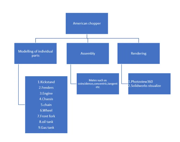
Fig. Design Methodology of the American Chopper.
Description-
The features and properties given inside the SOLIDWORKS Software makes it easier to compose a 3D Object from a 2D Sketch.
Let’s have a look into the features which is used in the process of modeling the entire model of the American Chopper:
1.Extruded Boss/Base.
2.Fillet.
3.Lofted Boss/Base.
4.Extrude Cut.
5.Split
6.Shell
7.Revolve Boss/Base.
8.Linear Pattern.
9.Combine.
10.Dome.
11.Mirror.
12.Projected Curve.
13.Reference Geometry.
14.Surface tools.
As we have gathered basic knowledge about the features in Solidworks, let us put this in modeling our American Chopper in Solidworks.
Now we are going to see each part associated with the American Chopper and its design process alongside.
Each design comprises of three major steps:
- Sketching a 2D Geometry with proper dimensions and relations.
- Applying features as required.
- Applying appearances to convey the nature and the properties of the solids accordingly.
Component Modeled-
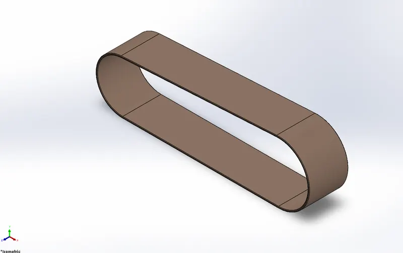
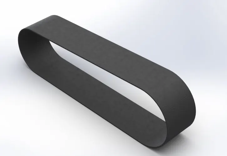
1.Transmission belt
Features used-
- Sketch
- Revolve
- Split
- Fillet
- Offset
- Extude
Part model image-
Rendered image-
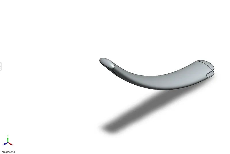
2.Kickstand-
Features used-
- Sketch
- Revolve
- Split
- Fillet
- Offset
- Extude
- Dome
Part model image-
Rendered image-
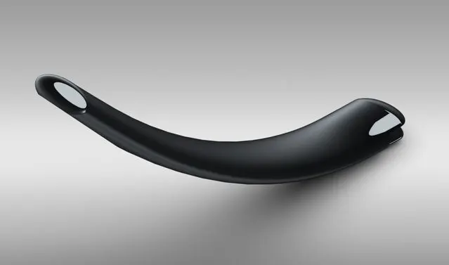
3.Frontfender
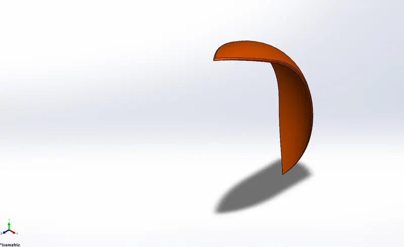
Features used-
- Sketch
- Revolve
- Split
- Fillet
- Sketch with dynamic entity
Part model image-
Rendered image-
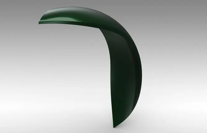
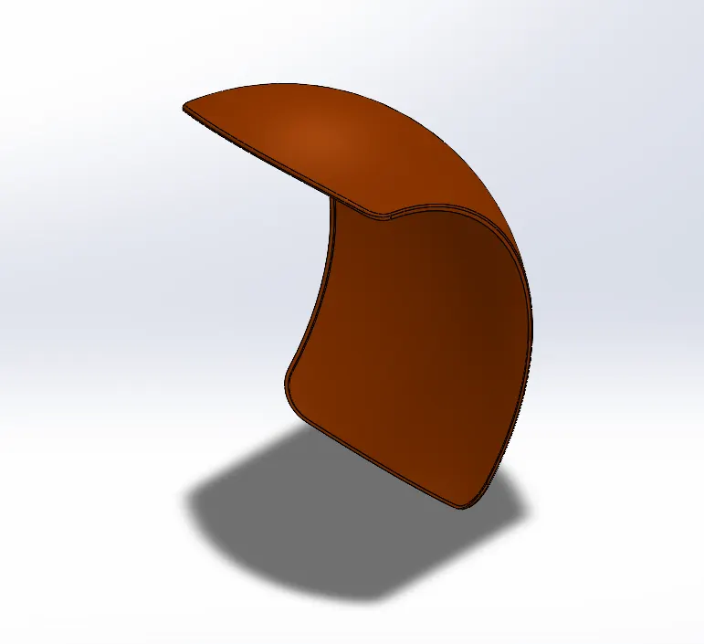
4.Rearfender
Features used-
- Sketch
- Revolve
- Split
- Fillet
- Sketch with dynamic entity
Part model image-
Rendered image-
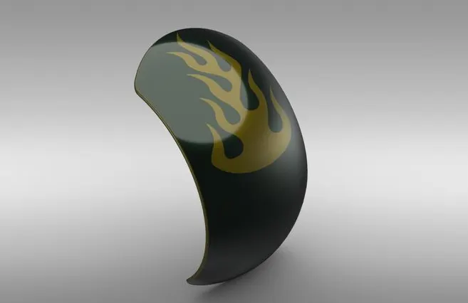
5.Oiltank
Features used-
- Sketch
- Revolve
- Split
- Fillet
- Offset
- Combine
- Shell
Part model image-
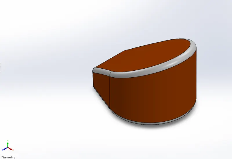
Rendered image-
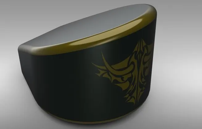
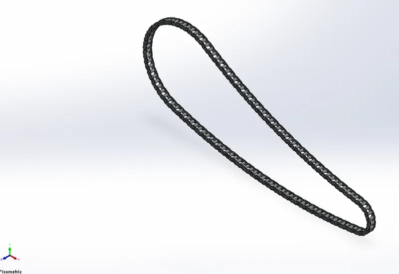
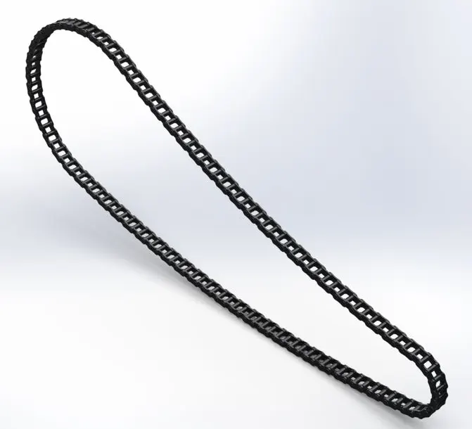
6.Chain
Features used-
- Sketch
- Revolve
- Split
- Fillet
- Offset
- Curve driven pattern
- Solid body folder
Part model image-
Rendered image-
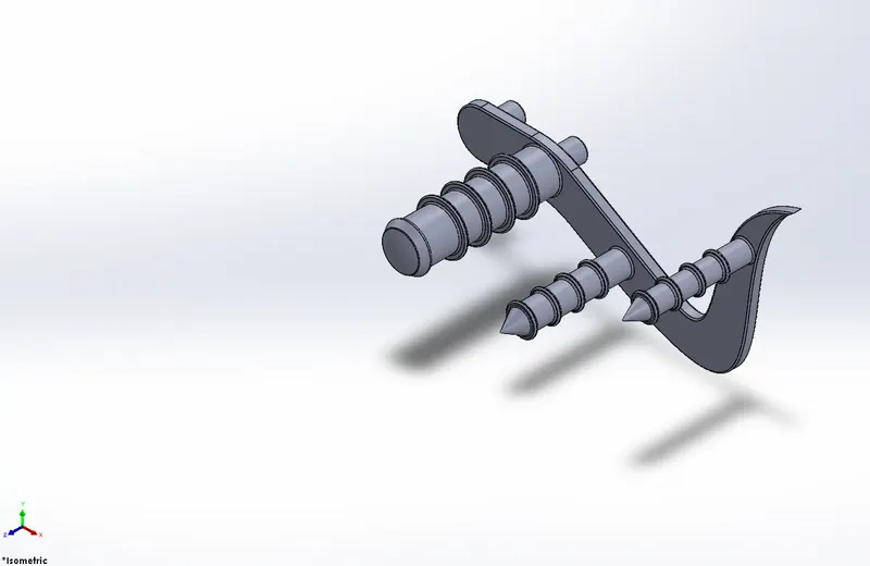
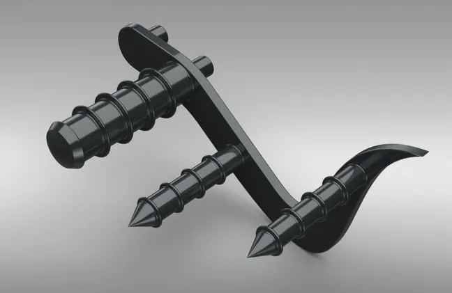
7.Pedal
Features used-
- Sketch
- Revolve
- Split
- Fillet
- Offset
- Extude Boss
- Linear pattern
- Chamfer
Part model image-
Rendered image-
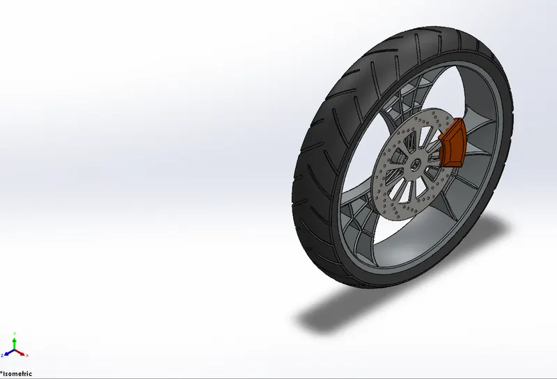
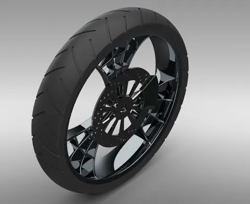
8.Frontwheel
Features used-
- Sketch
- Revolve cut
- Split
- Fillet
- Offset
- Extude cut
- Chamfer
Part model image-
Rendered image-
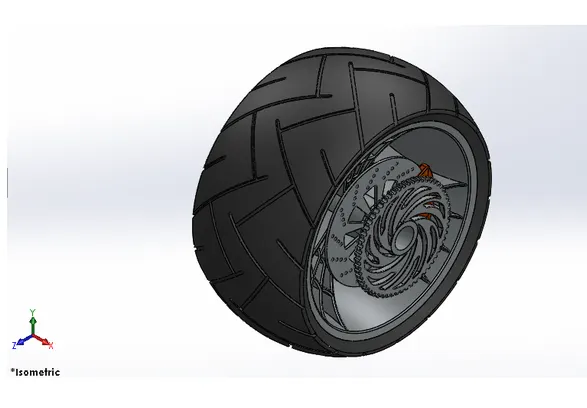
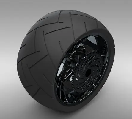
9.Rearwheel
Features used-
- Sketch
- Revolve cut
- Split
- Fillet
- Offset
- Extude cut
- Circular pattern
Part model image-
Rendered image-
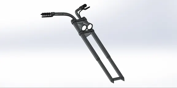
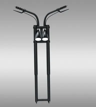
10.Frontfork
Features used-
- Sketch
- Revolve
- Split
- Fillet
- Offset
- Extude
- Combine
- Mirror
- Projected curve
Part model image-
Rendered image-
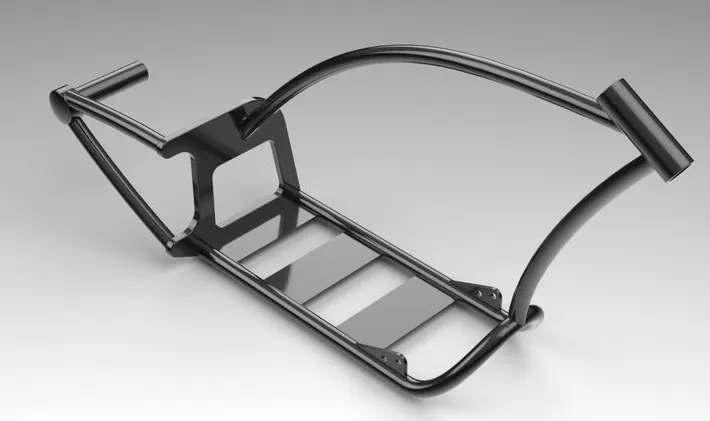
11.Chassis
Features used-
- Sketch
- Revolve
- Split
- Fillet
- Offset
- Extude
- Done
- Chamfer
- Mirror
- Composite curve
- Projected curve
Part model image-
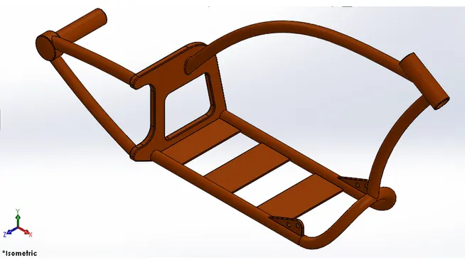
Rendered image-
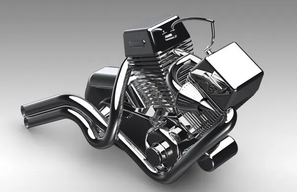
12.Engine
Features used-
- Sketch
- Revolve
- Split
- Fillet
- Offset
- Extude
- Composite curve
- Projected curve
- Chamfer
- Mirrior
Part model image-
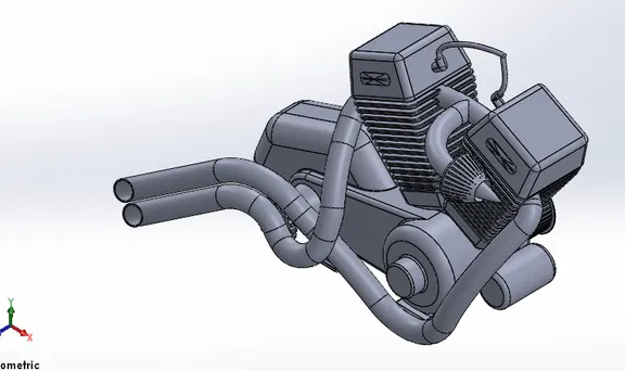
Rendered image-
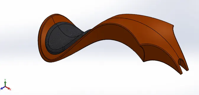
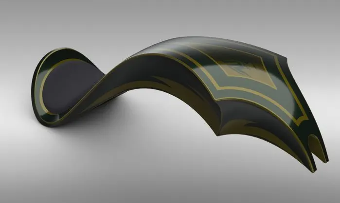
13.Gastank
Features used-
- Sketch
- Revolve
- Split
- Fillet
- Offset
- Extude
- Surface trim
- Sweep cut
- Convert entity
Part model image-
Rendered image-
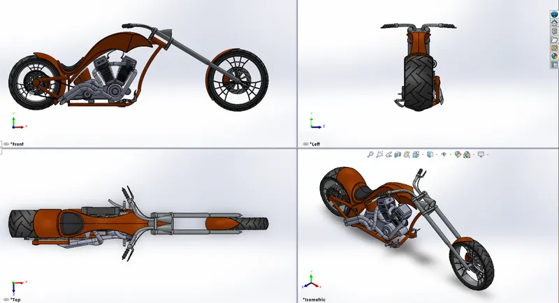
Assembly-
Procedure for Assembly-
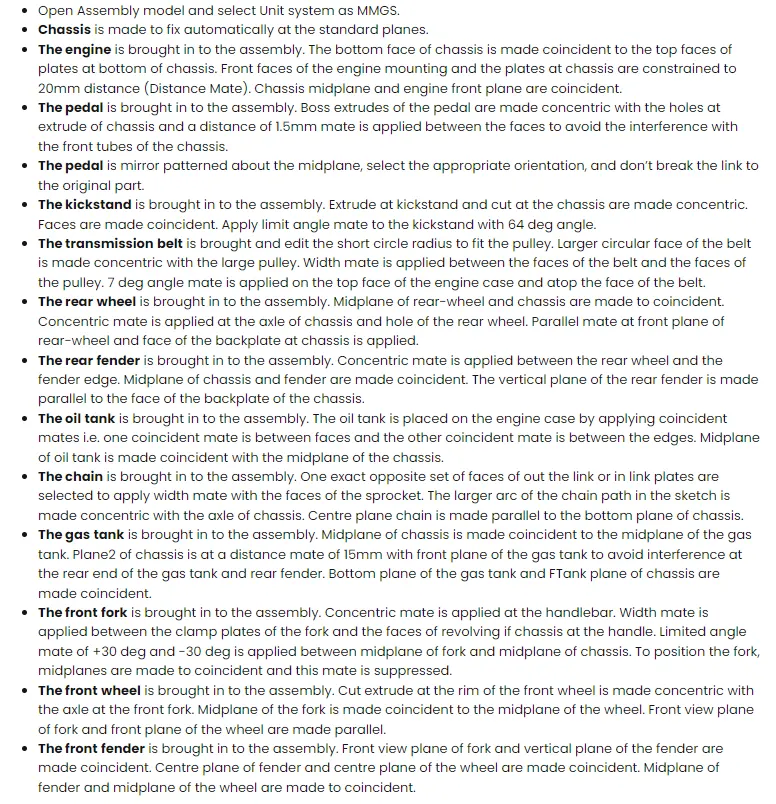
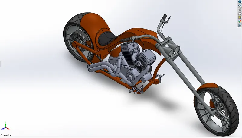
Various Views of Assembly of an American chopper-
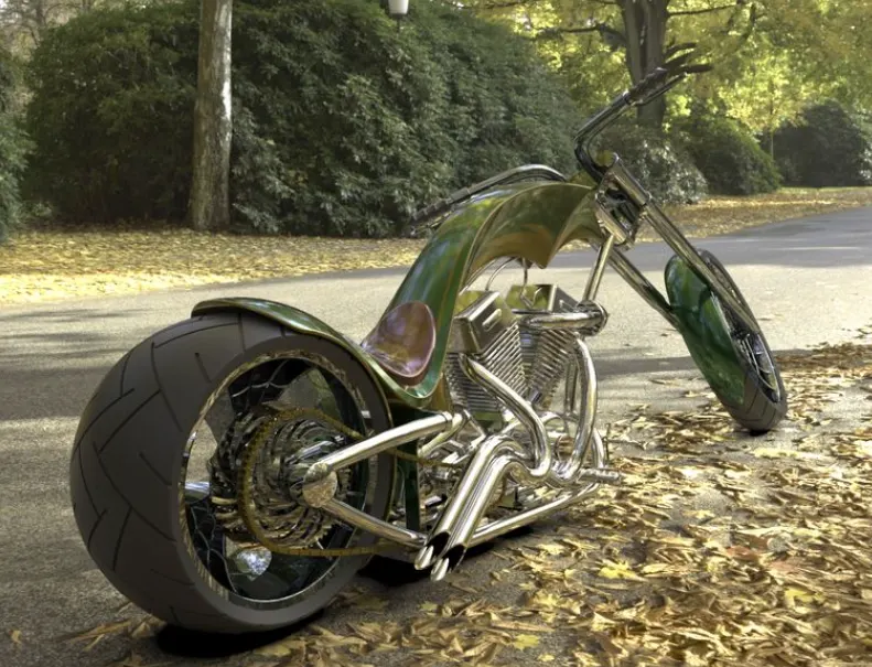
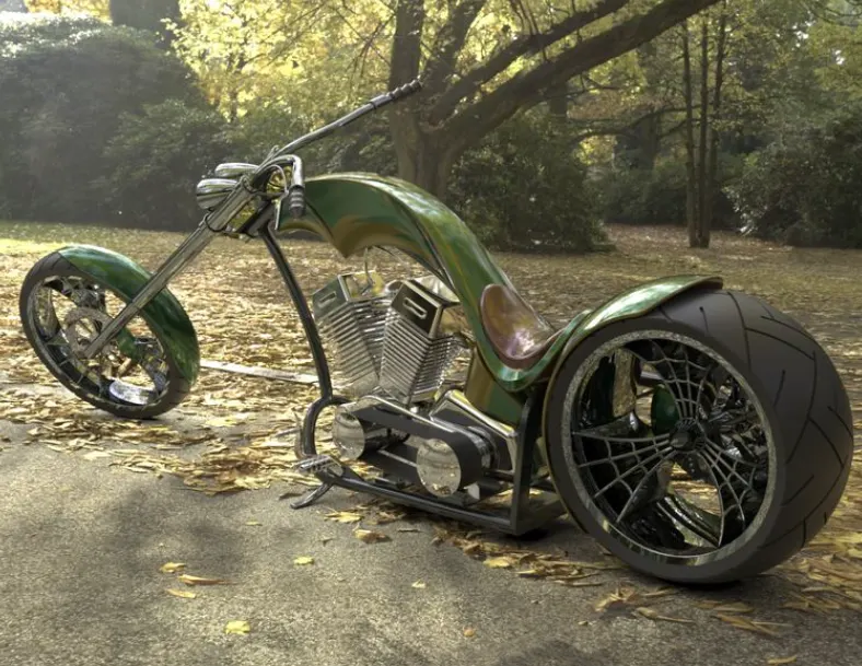
Rendered images-
Rendering is the process of generating a photorealistic or non-photorealistic image from a 2D or 3D model utilizing a computer program. At present, there are multiple computer programs available to perform the rendering.
The rendering of a CAD model in Solidworks can be done by using the following software & the first two software are widely used for rendering.
- Photoview 360
- Solidworks Visualize.
- Onshape
- Keyshot
- Blender
In order to render image for the object you must create a camera view otherwise you must enable perspective view.
In this project, I do the renders through Photo View 360 add-in.
Photoview 360 add-in can be found in menu tab by enabling it from ”Tools > Add-in” Option.
By enabling it you can also get a Render tools tab, from there you can edit a scene, edit decals and adjust the render option to render the object.
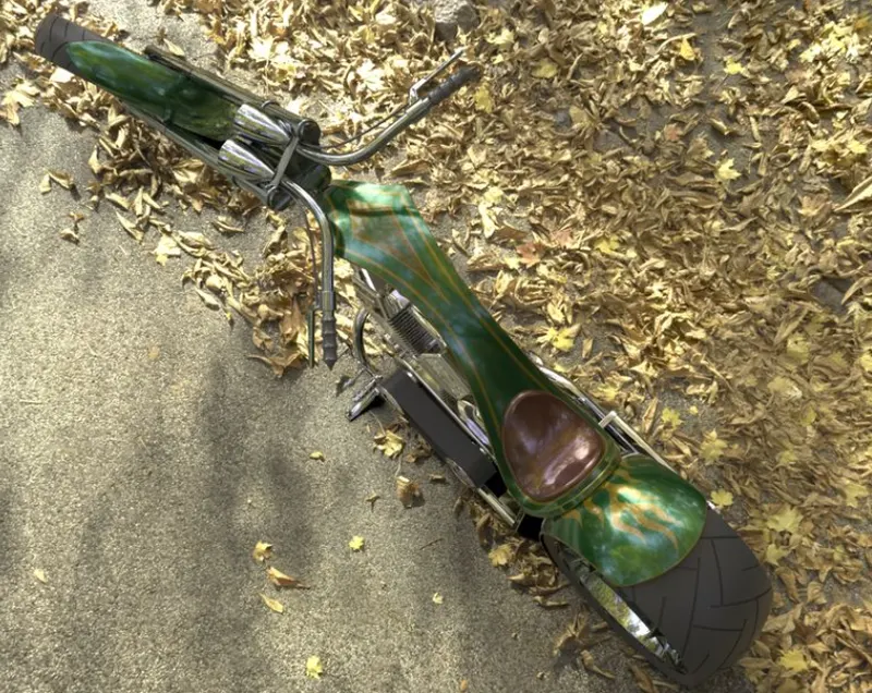
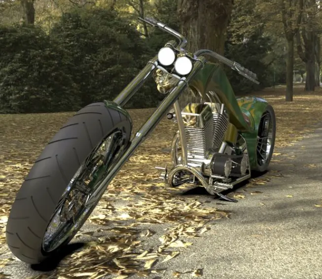
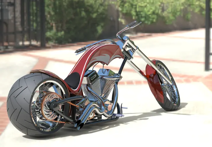
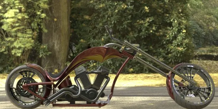
Following are the renders of the American Chopper in different views and in different environments.
In each render I adjusted the lighting brightness and environment rotation.
Conclusion:
The American Chopper is successfully modeled in Solidworks. The parts are modeled using Sketch, features and surface tools and assembled together with assembly tools like mates. Then successfully rendered to get a good product design of American Chopper using Photoview 360 add-in from Solidworks.Report file and link of zip file containing part files,rendering files and assembly file is also attached.
https://drive.google.com/file/d/1xdViEYzUhpHUI87hO7V_CG7fAnw6Zmka/view?usp=sharing