Photo Realistic Rendering
American_Chopper_Modeling & Rendering
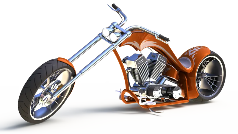
Objective:
To Model The American Chopper Project With The Help Of Solidworks Software Using Different Types of Tools & Features.
- Design the model components of the chopper using part features & tools.
- Assembly all the parts in assembly environments.
- PhotoRealistic Reandering using photoView 360.
Introduction:
Design the American chopper using Bottom Up approach in solidworks. Starts with creating each part files separately with the help of blueprint.
After designing the parts,Assembling each part to create American Chopper using mates.After Assembling, Render the model using photoView 360 & Solidworks Visualizer,
while rendering applying decals fro asthetic looks.Then applied lights & camers in differnet environments to get realistic output.
Design Methodology/Approach
BottomUP Approach:
First deisgn the model parts,Then insert them into an assembly & use mates to position the parts.
Flow Chart:
Part Modelling ⇒ Assembly ⇒ Rendering
The Parts we designed for creating the american chopper as mentioned below.
- Transmission Belt
- Kick Stand
- Front Fender
- Rear Fender
- Chain
- Oil Tank
- Pedal
- Front Wheel
- Rear wheel
- Front Fork
- Chasis
- Engine with exhaust
- Gas Tank
Part Modelling:
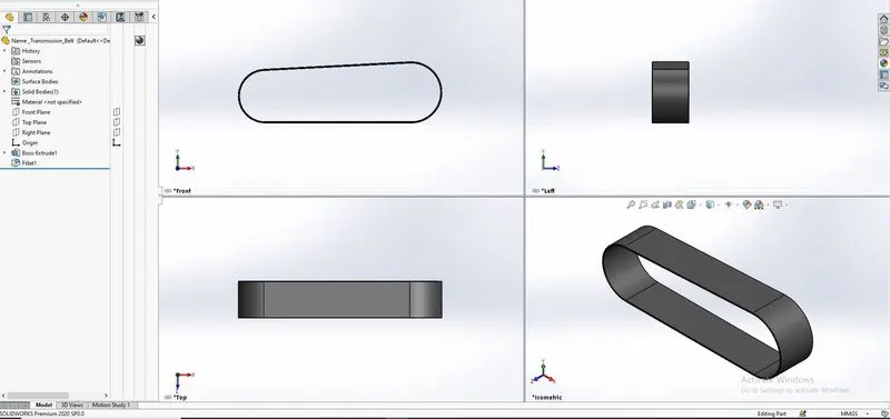
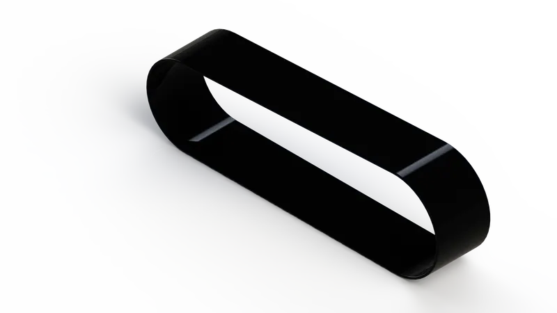
1.Transmission Belt:
Feature Used:
- Sketch
- Offset
- Boss Extrude
- Fillet
- Apperance-rubber
steps followed
Sketch the profile on a plane,using sketch tools,then extrude it .after that fillet the edges for a smooth corner.
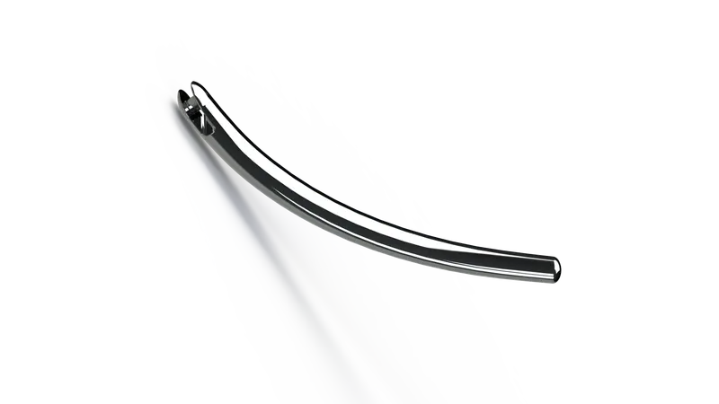
2.Kick Stand:
Feature Used:
- Sketch
- Loft
- Dome
- Cut Extrude
- Boss Extrude
- Split
- Fillet
Steps Followed
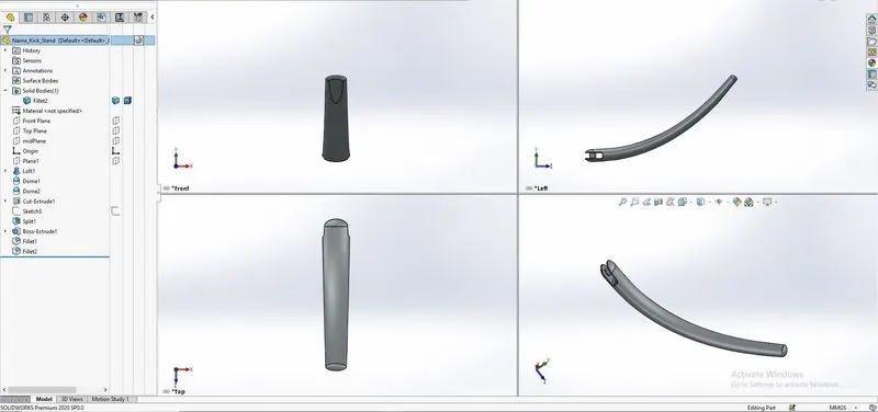
Sketch a spline on a plane,make the fully defined using diemnsions and other geometrical features.
two planes were created at the end of the spline.using those planes create ellipse.
loft boss feature used to create the solid body. on both ends eliptical dome was provided.
for complete teh model other features are made by split and extrude cut option to get the desire shape.
3.Front Fender:
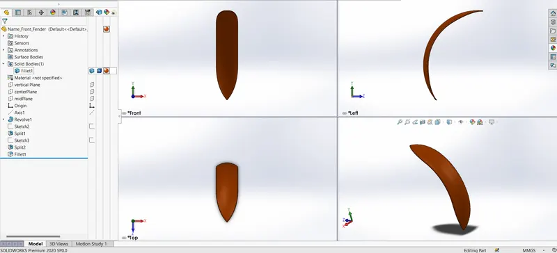
Feature Used:
- Sketch
- Revolve
- Split
- Fillet
Steps Followed
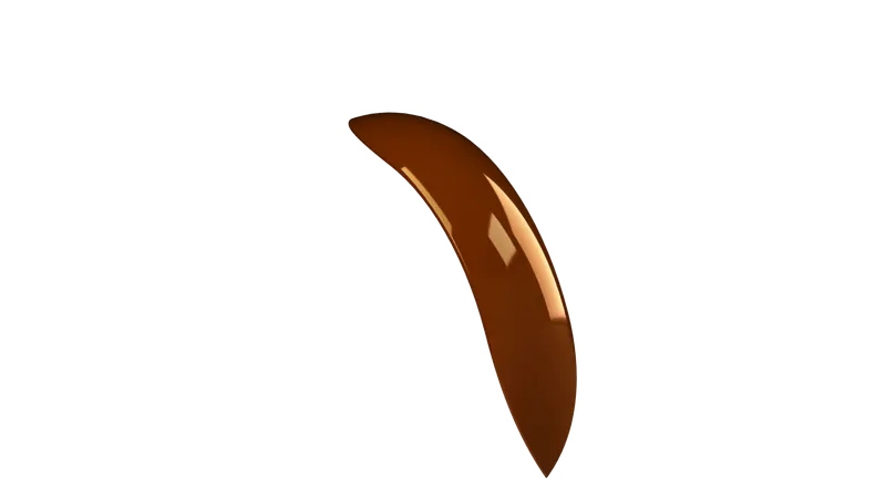
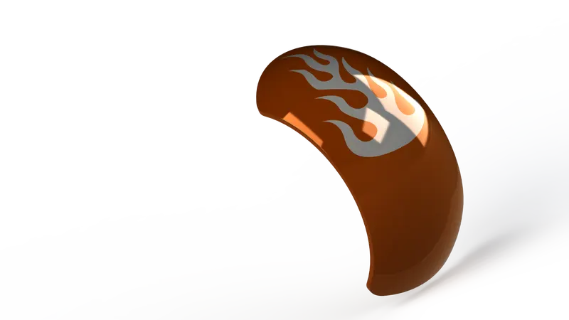
Sketch a 3 point arc create the shape on plane.revolve the sketch upto certain starting angle & ending ending angle.
2d sketch created to split out the extra metal from body to get the desire shape.
fillted the edges fro make them smooth.
4.Rear Fender:
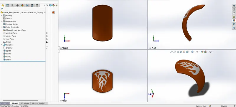
Feature Used:
- Sketch
- Revolve
- Split
- Fillet
- Shell
Steps Followed
Sketch a 3 point arc create the shape on plane.revolve the sketch upto certain starting angle & ending ending angle.
2d sketch created to split out the extra metal from body to get the desire shape.
shell inside of the fender to get the desure equally thin shape .
fillted the edges fro make them smooth.
5.Chain:
Feature Used:
- Sketch
- Boss Extrude
- Block
- Fillet
- Circular pattern
- Mirror
Steps Followed
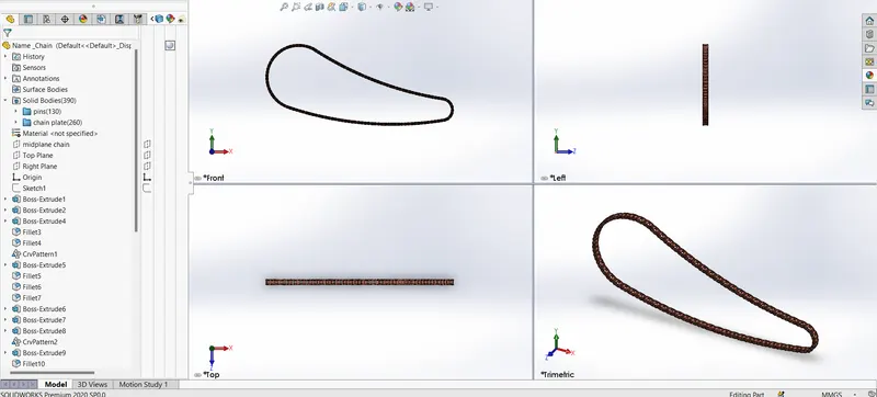
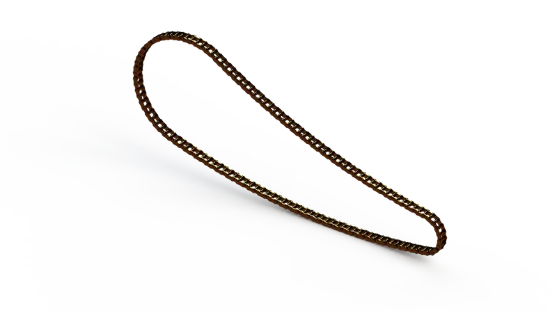
Sketch a base curve using circles & 3 point arc on which the chain will be create.
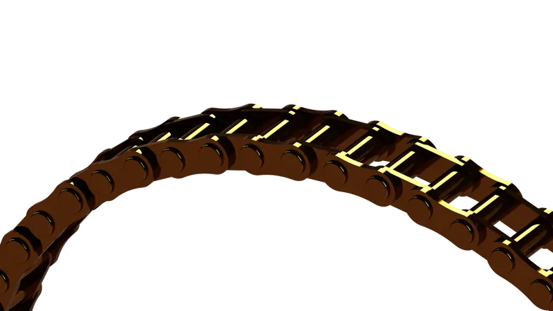
create the chian link1 & link2 sketch,convert them into blocks for further use in the chain,
arrainge them with curve drive pattern ,at some places sketch block used again for get better arrangement on the shape of chain.
fillted the edges fro make them smooth.
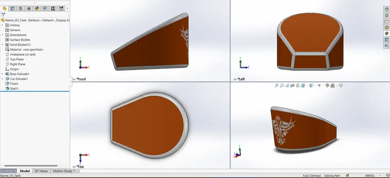
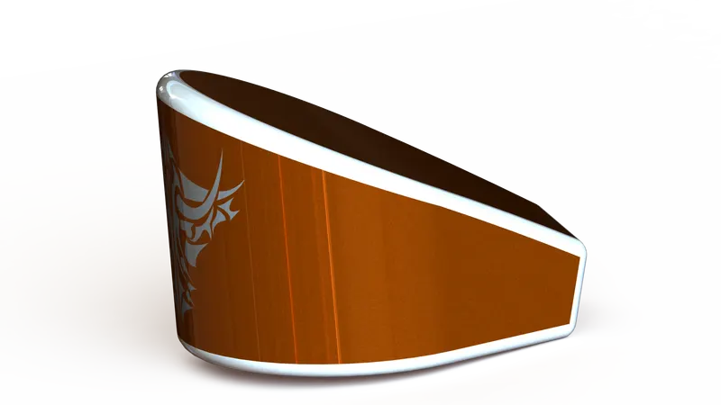
6.Oil Tank:
Feature Used:
- Sketch
- Boss Extrude
- Block
- Fillet
- Circular pattern
- Mirror
Steps Followed
Sketch the shape using circles and trim to get desire shape.
boss extrude the sketch to creata body after cut extrude to remove extra metal from body.
make fillted the edges fro make them smooth.
shell the part tomak hallow from inside.
7.Pedal:
Feature Used:
- Sketch
- Boss Extrude
- Fillet
- Revolve
- Dome
- Chamfer
- Liner pattern
Steps Followed
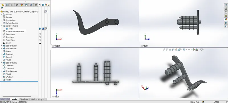
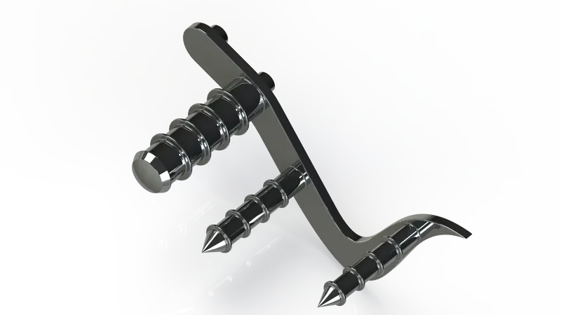
Sketch the shape using splines and dimension to get desire shape.
boss extrude the sketch to creata body after cut extrude to remove extra metal from body.
revolve done for the foot rest & at the dome is added.
make fillted the edges fro make them smooth.
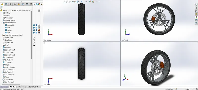
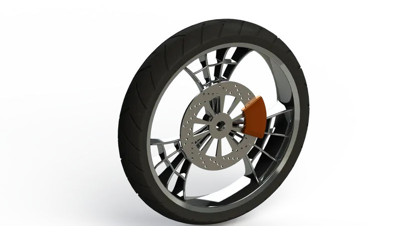
8.Front Wheel:
Components:
- Rim
- Break calliper
- Break Rotor
- Tire
Feature Used:
- Sketch
- Boss Extrude
- Cut Extrude
- Fillet
- Dome
- Revolve
- Chamfer
- circular pattern
- Combine
Steps Followed
Sketch a 3 point arc create the shape on plane.revolve the sketch 360° using the centerline to get the shape.
spider wave design sketch created and extruded then cut extrude to get the spider wave shape.
circular pattern doen to make dubilcates of the spider wave design & then combined with rim
fro tire revolved the sketch using the center axis of the rim,then cut outs are done on the tire surfaces using extrude cut-offest from surfaces,
fillted & chamferd the edges fro make them smooth.
9.Rear wheel:
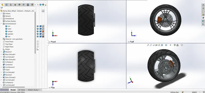
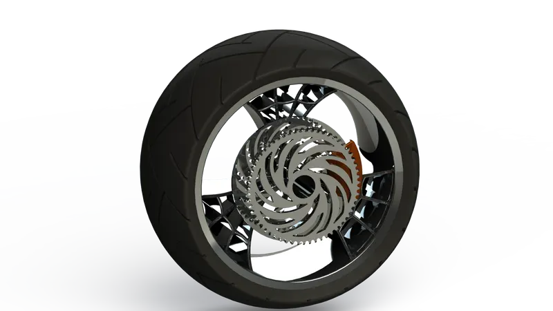
Components:
Rim,Break calliper,Break Rotor,Tire
Feature Used:
- Sketch
- Boss Extrude
- Cut extrude
- Fillet
- Revolve
- Dome
- Chamfer
- circular pattern
- combine
Steps Followed
Sketch a 3 point arc create the shape on plane.revolve the sketch 360° using the centerline to get the shape.
spider wave design sketch created and extruded then cut extrude to get the spider wave shape.
circular pattern doen to make dubilcates of the spider wave design & then combined with rim
fro tire revolved the sketch using the center axis of the rim,then cut outs are done on the tire surfaces using extrude cut-offest from surfaces,
fillted & chamferd the edges fro make them smooth.
10.Front Fork:
Feature Used:
- Sketch
- Revolve
- Boss Extrude
- Cut Extrude
- Fillet
- Linear Pattern
- Revolve cut
- dome
- Projected Curve
- Sweep
- Mirror
- Combine
- Copy/Move
Steps Followed
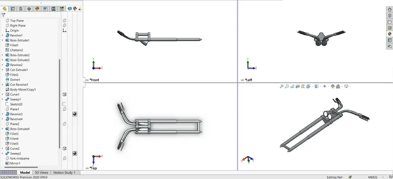
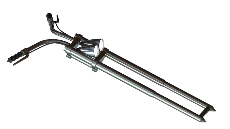
Sketch the shape using line & revolve it 360° by centreline .
make the trple clam base & extude .then attach the head lights by revolve using splines sketch then shell it for make hallow.
create handle using projected curve then swept . creathe the handle using revolve,then add brake wire,
after one side complete mirror the entire model to complete the front fork.
11.Chasis:
Feature Used:
- Sketch
- Offset
- Convert Entities
- Project curve
- Plane
- Swept
- Split
- Revolve
- Boss Extrude
- Cut Extrude
- Fillet
- Combine
Steps Followed
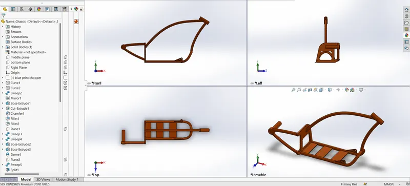
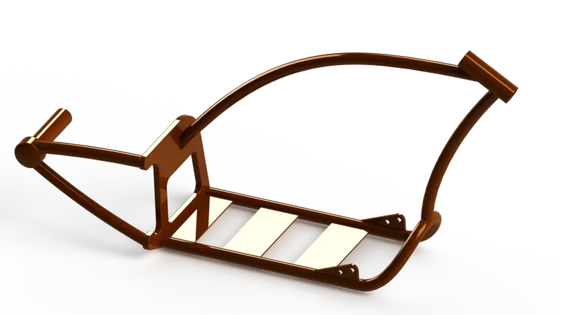
Sketch using the blueprint & using sppline draw the desire shape then project curve to get 3d curve ,
after swept with sketch to get the solid body.
using the existing referenace cerate the handle rest tube & engine base portion of chasis.
use split consume bodies to get our desire shape on the intersected tube section.
after all the part dome combine it make it single solid body.
fillet the edges to get a smooth corners.
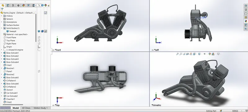
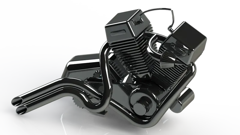
12.Engine:
Feature Used:
- Sketch
- Boss Extrude
- Fillet
- Revolve
- Plane
- Circular Pattern
- Dome
- Cut Extrude
- Chamfer
- Linear Pattern
- Split
- Mirror
- Swept
- Combine
- Curve
- Composite Curve
Steps Followed
This is the suffecticated part in this entire chopper model.
this model is a combine of 3d curves and other solid features using swept ,linear pattern,
Sketch using the blueprint & using spline draw the desire shape then project curve to get 3d curve tehn sweptfro exhaust pipes.after swept with sketch to get the solid body.
after all the parts made filled them to make the sharp corner smooth.
after all the part done combine it make it single solid body.
13.Gas Tank:
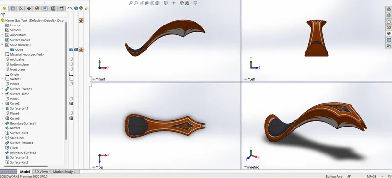
Feature Used:
- Sketch
- Projected Curve
- Split Line
- Surface Trim
- Fillet
- Shell
- Mirror
- Swept,
- Lofted Surfaces
- Extrude Surfaces
- Boundry Surfaces
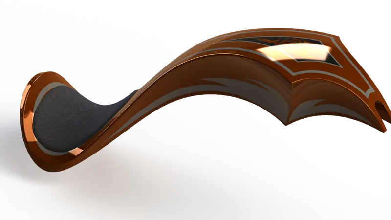
Steps Followed
sketch the spline using blue print,then convert projected curve to get the desire shapes.
after curves generated create surfaces using curves and trim the unwanted surfaces.
after all the sufaces were made sew them and covert into solid.
afetr solid generated shell for a equally thickness tank.
Assembly:
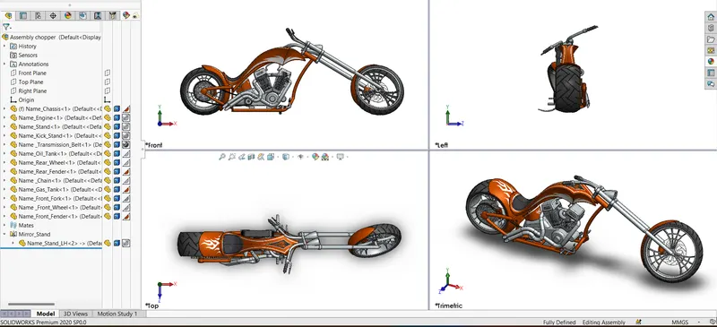
After all the parts been created & imported them to the assembly.
start with chasis first & made it fix for further refference.Then connect all the parts using diffrent types of mates. Inculdes concentric,co-incident,parallel,
pierce ,etc.Some of the parts were modified in the assembly to make it as per requirment.
Rendering:
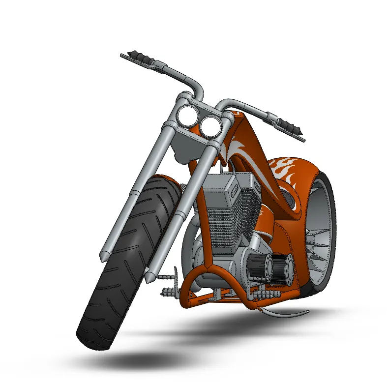
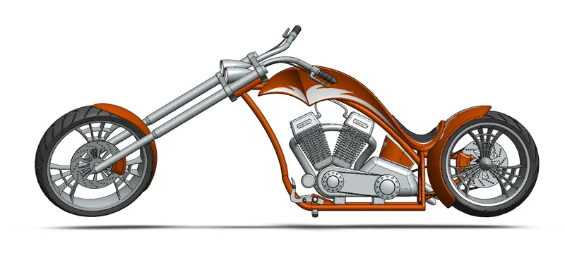
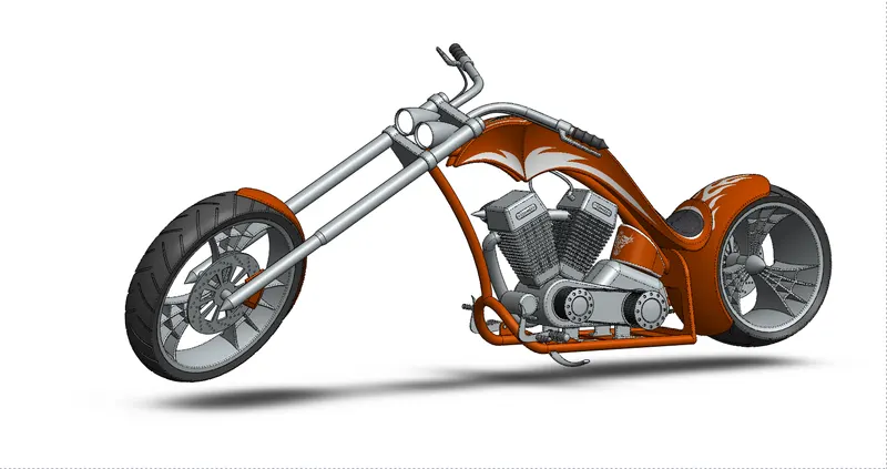
Enable photoview 360,there set up the scenes add lights & backgrounds to the scene in graphics area.
camera setup
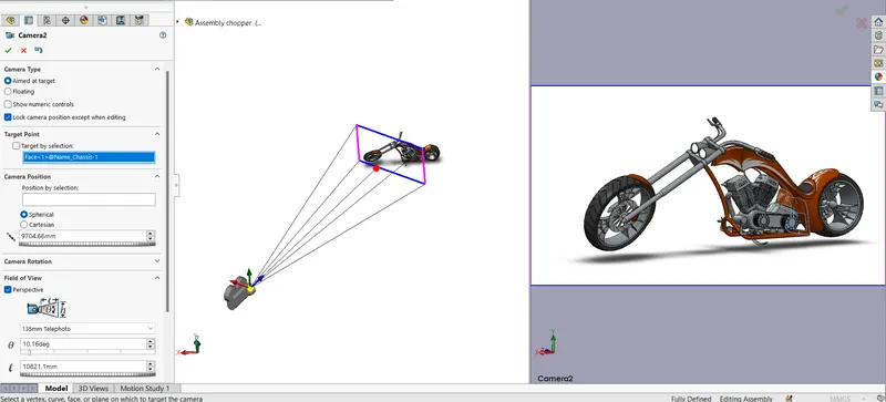
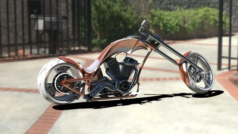
Rendering in PhotoView 360
Rendering in Solidworks Visualizer
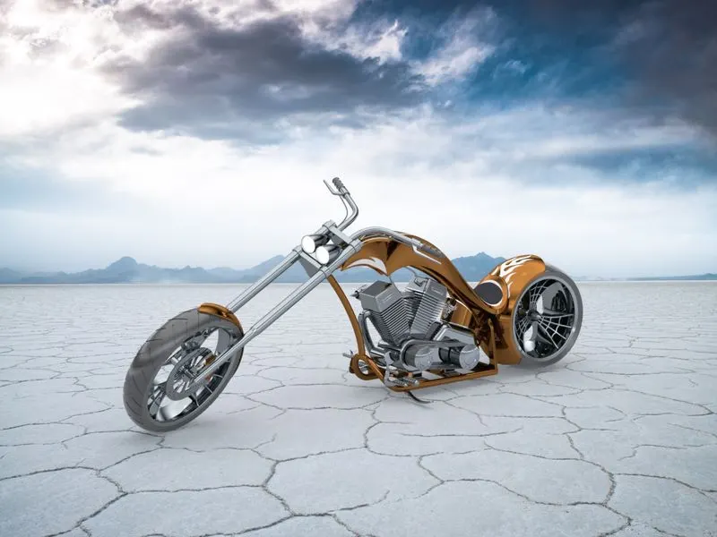
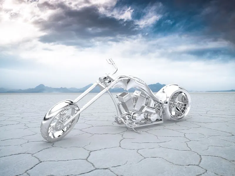
Conclusion
after all the process from the scratch to to the end final prdoduct .it was really interesting & through this we learned a lot more about software with features & approaches for our future improvement.