Photo Realistic Rendering
title:
desiging, modelling ,assembly and photo realistic rendering of american chopper
objective :
objective of this project is to get an understanding of basic solidworks tools for designing ,modelling and assembling of the parts
introduction:
this report consists of basic explantion of the designing and modelling of the chopper parts and assembling these parts inorder to get an american chopper along with the rendering of the parts
flow chart:
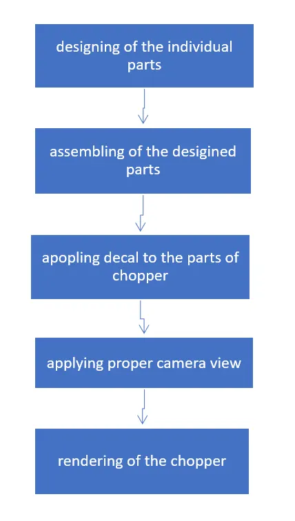
description:
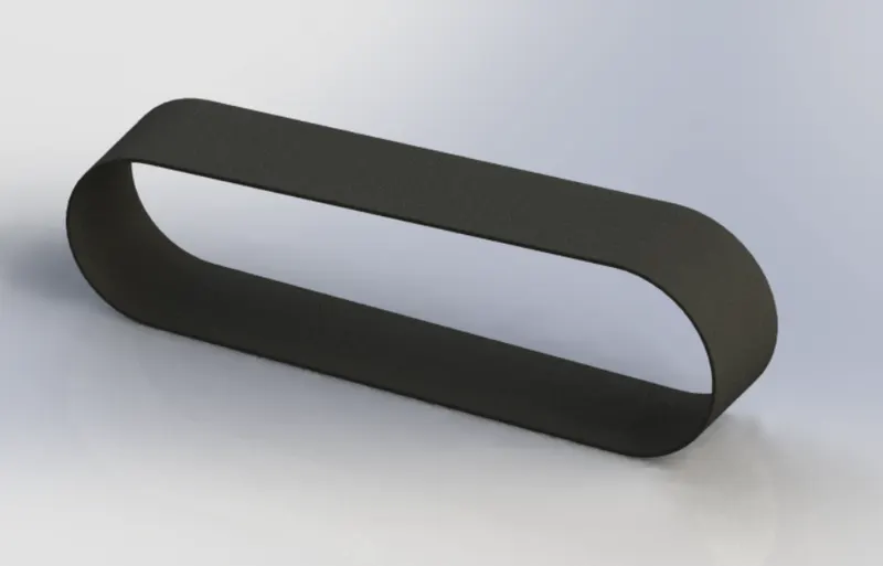
1.transmission belt:
- select the front plane and draw two lines closed
- close the two lines with the two arcs in tangent with the size line with 350mm length
- the diameters of the circles are d1-140mm d2 - 160mm
- use offset option and select the the sketch drawn to offset of 6mm thick
- now exit the sketch and extrude it with a thickness of 88mm
- select the appereance tool in order to apply the colour
- pick a rubber matt black and apply to the belt
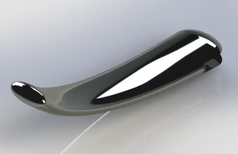
2.side kick stand
- select the front plane
- draw a ellipse of length 40mm, width 18mm in the front plane
- select the right plane use spline with a length of 225 mm as mentioned
- now on the other end of the spline create a plane perpendicular to it and draw an another ellipse of length 30mm and width 12mm
- use loft base tool select the ellipse and centerline thus creates asolid
- create dome of 10mm in bigger face and domes of 5mm on smaller face
- now select the mid plane and draw a rectangle of length 28mm and height 8mm cut the part from solid using extrude cut
- draw a circle of diameter 8mm on the center of the ellipse and extend upto next surface
- select the front plane and draw a line on stand to height of 4.5mm from bottom of the stand
- use split option select the line ,select the part to cut and press ok
- provide fillet to the edges
- use appereance tool and select the colour
- apply metallic sillver to the solid
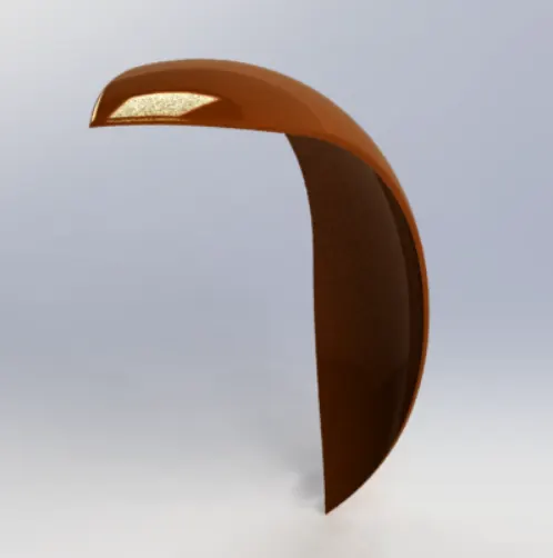
3. front fender:
- select the front plane and draw an arc
- radius of the arc is 125mm and also the select to two edges select the horizontally equal
- length of the arc is considered as 160mm , provide center height of 280mm
- use offset tool and select the object offset inside provide a thickness of 6mm
- draw vertical lines from the corners, use trim extend to extend the offset curve to lines and trim the remaining lines
- create a center line and revolve it using revolve command with 5 degrees at direction 1 and 130 degrees at direction 2
- select the mid plane , use spline to provide a curve such that it is point 1 is 50mm horizontal and 45mm vertical ,point 2 is 200mm vetical from origin
- use split tool select the line and cutpart select the part to be cut and done
- repeat the same procedure to the other end
- use fillet of 6mm radius on to top face
- use apperance option to provise colour of sieana
4. rear fender:
- select the front plane
- draw an arc of radius of 290mm and also select the two edges of curve and then select horizontally equal
- provide a length of 364 mm and a center height of 90mm
- now offset the arc to 6mm
- draw vertical lines from the corners, use trim extend to extend the offset curve to lines and trim the remaining lines
- create a center line and revolve it using revolve command with 10 degrees at direction 1 and 140 degrees at direction 2
- select the mid plane
- use arc with both corner of either of the fender and make sure the are horizontal
- and also make them horizontal to origin and provide a length of center height of 227mm
- select the fillet and select the corners and provide a radius of 45mm
- and also give 4mm on top of th face
- use appereance tool to colour to sieana
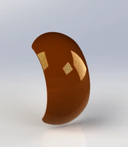
5.oil tank
- a 2d sketch is created as per the given dimensions in the top plane
- then the sketch is extruded on both directions 170mm on one side and 10mm on other side
- a new sketch is created on the midplane and extruded into both sides using through all option
- combine the feature is used to build a commam part using both the models
- fillets are used at the edges
- shell feature is applied with a thickness of 3mm and previewed with the help of sectional view
- appearance of oil tank is changed to siena with white at the edges
- then saved
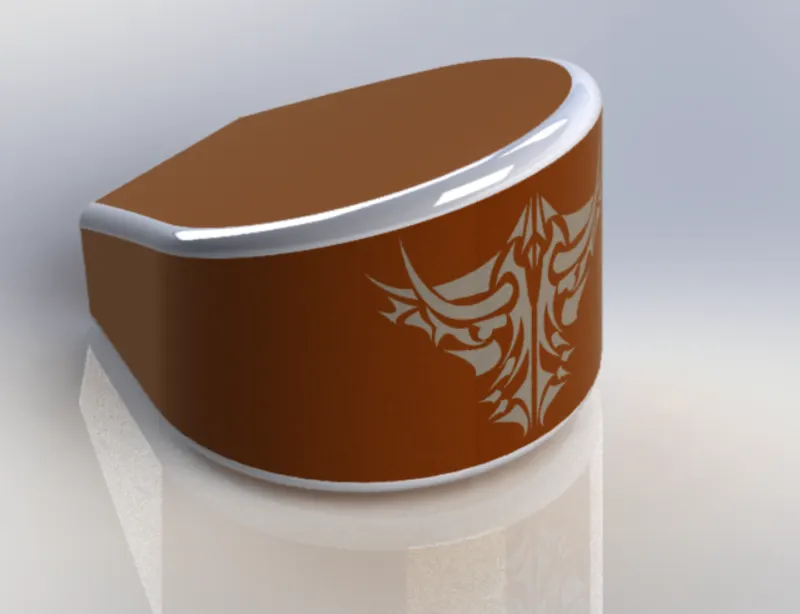
6.chain
- rename the planes as per the construction required mentioned
- select the midplane and sketch is created as per the given dimensions
- a run away sketch is created at the midplane and blocks are created as chainlink1 and chainlink2 inorder to save them as a seperate part and use them to create links
- these blocks are inserted on to the 2d sketch created o the midplane and applied certain relations to make coincident with curve
- these blocks are then extruded and fillets are applied at the faces of the pin'
- curve driven pattern is applied along the curve and some extrudes are drawn manually to perfectly allign with chain path
- then chain bodies are classified into chain plates and pins in seperate folders to keep them more organised
- these chain plates are mirrored uding mirror entities
- chrome appearance is applied to the chain
- part then saved
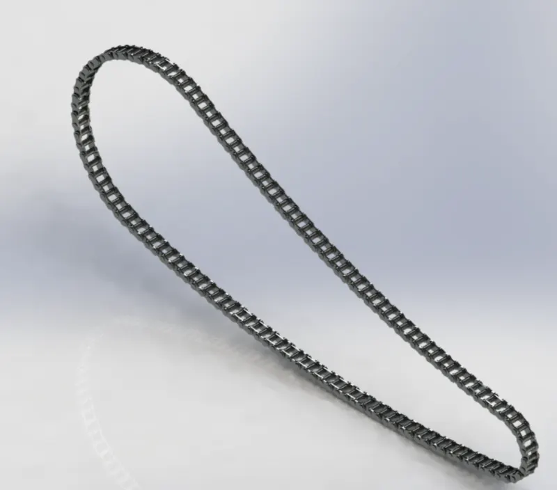
7. pedal
- a 2d sketch is created at the front plane as per the given dimensions and then extruded using extruded boss/base upto 8mm
- a new sketch is created on the front face of the model and extruded upto 20mm
- and another sketch is created on the other side of the face and is revolved using revolved boss/base feature
- dome feature is applied at the end of teh revoved part
- unsymmetrical chamfer is applied to the other two parts
- a new sketch is created by using offset entites option at the base of the three parts and is extruded from the faces at an offset of 20mm of 2.5mm
- fillets are applied to all newly created edges with 1mm radius
- an linear pattern is applied to create four instances of the same at a spacing of 20mm
- fillets are then applied to the reamining formed edges
- part then saved
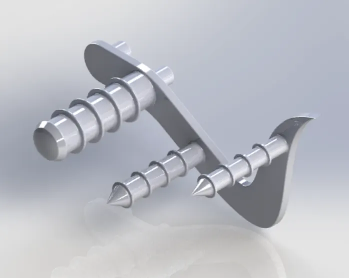
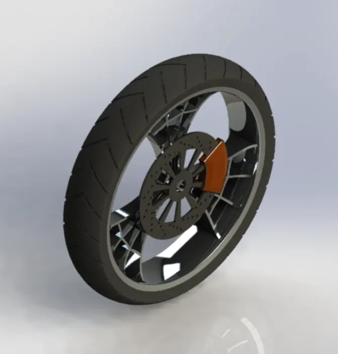
8. Front Wheel
the front wheel here designed having mainly four parts
- rim
- rotor
- caliper
- tire
rim:
- select the rightplane and sketch the geometry as per the given dimensions
- now use revolve command in order to get complete curvature of the rim
- use right plane and sketch the spokes as per the dimensions mentioned and use extrude cut feature inorder to get the spokes
- connect the ribs of spokes to the rim by using combine geometry option and add and then use circular pattern in order to get two more ribs od spoke
- now go to combine feature add hub ,rim and ribs as a single body
rotor and caliper:
- take front plane of hub as the referance plane and sketch the rotor as per the given dimensions
- extrude the geometry by offset away from the hub
- sketch a circle of dimeter of 8mm and use linear pattern and select circles with an angle of 142 degrees
- use a circular pattern to mirrors the holes to a no of 14 sets
- on the same plane sketch the caliper as per the given dimesions
- extrude the sketch on the both directions and use camfer the front face using distance to distance option of 8mm and 20mm
- and then apply fillet of 4mm to all the edges of the caliper
tire:
- select the front plane and thenclick on the convert entities to get a referance line on the front plane and then change it to construction line
- now use revolve feature to the sketch by taking and referance of centre line to create the outer pheripery of the wheel
- selct the front plane to create threads on tire
- use rectangle sketch to sketch the enties as per the given dimensions atotal of 4 rectangle are sketches with an realtion to the origin
- use extrude to rectangles by an offset extrude cut 4mm from the surface
- use circular pattern to get a total of 14 sets of threaded sets on the tire
appearances:
- apply a matte rubber appearance to the tire
- apply a carbon stell to the rotor
- apply siena to the caliper
- apply chromium plate to the rim
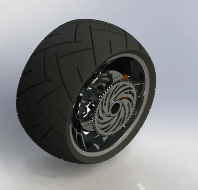
9.rear wheel:
rear wheel modelled here consists of five parts
- rim
- brake rotor
- calliper
- sprocket
- tyre
rim:
- by sketching on the right plane and using revolve command and then created two rough body referances ,also there is a need for the further adding and removal of materials
- then create spokes by using a constraints drawn sketch and the boss extruding
- then remove the curved shaped material by extrude cut on the centre plane by taking the referance geometry as roughly extruded spoke elements
- then draw ribs geometry to connect the extruded spokes of rim
- after then the spokes and the outer periphery was ready so i used circular pattern to get spokes
- use combine feature to add all the parts
rotor and calliper:
- consider the front face of the hub as the referance sketch plane then sketch the rotor dimensions and offset and extrude from the hub
- draw acircle on the front face ,extrude the circle and use linear pattern
- use circular pattern to create multiple combinations of linear pattern over the circumferance
- a caliper is created as aconstrained sketchon the pervius face and extrude that
- a camfer is given to the face of the calliper
- fillet is applied to the edes of the calliper of different radius
sprocket:
- sketch the dimentional entities by taking referance of rotor front face also offset the entities with out merging the results
- then provide an fillet to the extruded part
- use circular pattern around the circumferance od the sprocket
tyre:
- use convert entities option take a referance of the rim curve and sketching the geometry of the tyre
- crate a sketch make the revolve option to create outer periphery
- then threads geometry are sketched on the tyre and the extrude cut to cut the material from the tyre
- use circular pattern over the revolved tyre to get the complete thread over the tyre
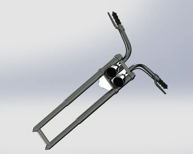
10.front frok:
- sketch the fork and revolve the sketch geometry
- then model the supporting memeber by selecting the prescribed plane
- then model the head light by using the feature of spline and revolve
- to model the handle use the projection of two curves and use the intersection curve to model
- then using the handle bar, crate a referance plane on the sweep axis using the revolve command
- use the same projection of curves to get the brake wire axis line
- then mirror the all the bodies, then combine the necesary components
- apply suitable appearances to the components of the front fork
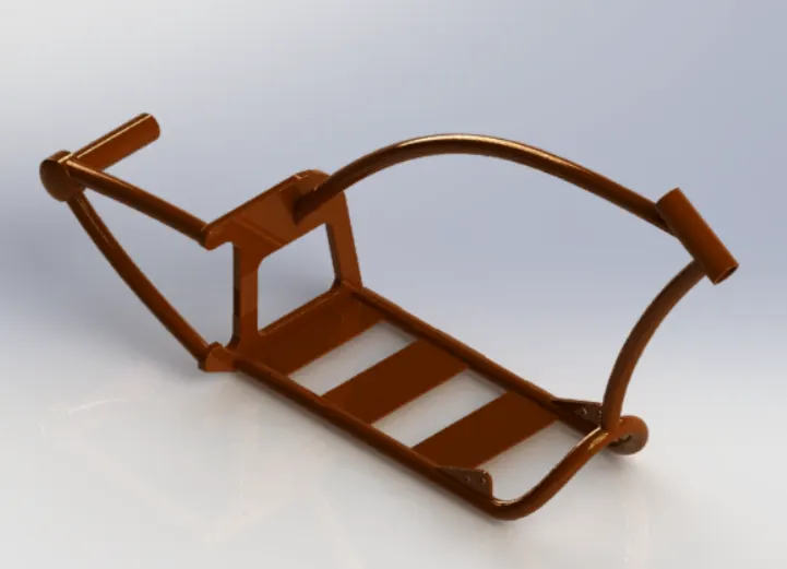
11.chassis:
- add the ble print sketch to mid plane
- sketch a curve on both bottom plane and the mid plane using projected curve option
- draw an another sketch on the right plane using the projected curve to draw a curve
- use aswept boss tool sweep abody through the curve
- mirror the solid sketch created
- skectch on the right plane and extrude it
- use a extrude cut option to remove portion from the extruded part
- create a referance plane parrale to mid plane and sketch on face ahown draw to concentric circles to sweep
- using the split tool cut the part atthe end
- after an another tol about the bottom plane and draw another sketch on it and also draw a curve on the mid plane
- after that combine all parts
- sketch on the midplane and then extrude with the merge option turned on
- fillets are given to the to all the edges with suitable radius
- draw an another sketch on the midplane and themn extrude the part
- now draw an another sketch on the right plane and then extrude and various fillets are given
- given an apperance of sieana to the combined part
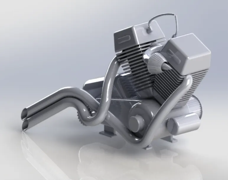
12. engine part:
- the blue print of the chopper is added gto the front plane
- various sketches are given on the front plane and then extruded
- sketch on the right plane and is revoved to make a part
- a new plane with respect to the right plane and draw a sketch on the plane and revolve
- draw a sketch on the front plane and extrude
- use a circular pattern option make the teetch of the chain
- repeat the same pattern to the other sprocket
- provide domes to the created parts
- a sketch is drawn on the front plane and is cut extruded to make holes on the sprocket
- certian fillets and camfers are given to the parts
- another sketch is drawn on the front placne and is extruded after that one more sketch id drawn on the same plane
- a new sketch is drwan on the front plane and a new plane is created with respect to the sketch
- now sketch is drawn on the newly created plane and are then extruded
- two more sketch are drawn on the newly created plane
- camfers and fillets are provided to the edges
- then sketch is drawn an the same plane and is then extruded to create a shape
- to copy this sketch linear pattern optio is used
- fillets are applied
- then sketch is drawn on the cylinder that is created and is then extruded outward and dome is given
- shape is mirrored on the both sides of cylinder
- a sketch is drawn on the front plane and is then extruded and fillets are applied
- use split option some parts are removed
- entire cylinder is then mirroed to back side
- fillets are given to the edges
- then somes sketch are drawn on the top plane and are extruded and certain fillets are given
- sketches drawn on th efront plane and are extruded and camfered
- now a small sketch is drawn on the sprocket created and is then extrude cut and fillet is given
- then use circular pattern option to copythe cut throughoutthe sprocket
- camfers are provided
- another sketch id drawn on the front plane and another on right plane
- then it is swept using the sweep tool to make the exhaust tube
- all the parts are then combined
- then a plane is created with respect to the top plane
- another sketch is drawn on the front plane a curve is drawn on that is previously created this sketch is used to swept part
- again a sketch is drawn on the front plane and is revoved to make the air intake
- various fillets are applied
- then a sketch is drawn on the top plane and then it is extruded and using a circular pattern tool the cuts is copied throughout the part
- then make the exhuast tube 4 curves are drawn differnet planes and using projected curves options to make curve and using the swept option make a sweeping part
- follw the same procedure to other exhaust pipe
- then sketch tha face of the spark plug and another curve on the front planes so that it can be used to make the wire of the spark plug follow the same procedur eto other plug
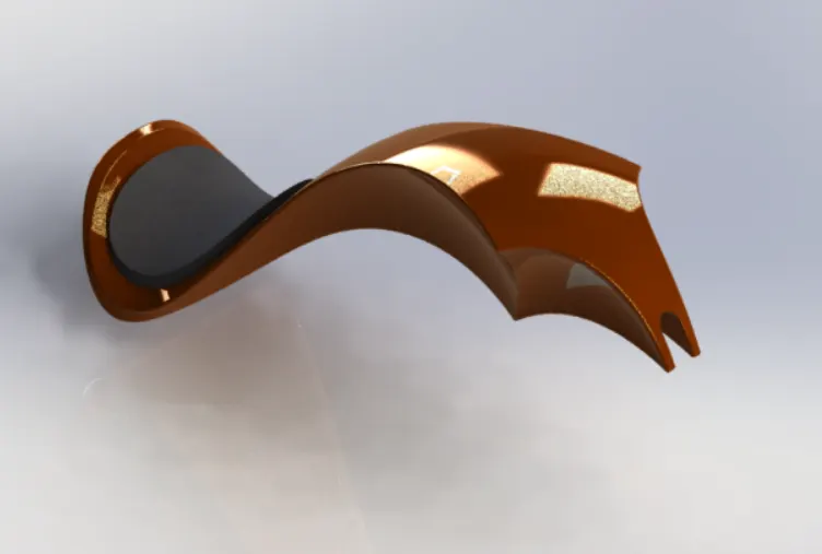
13.gas tank:
- start a sketch on the midplane and draw a spline and surface extrude it
- thyen draw a sketch on the top plane and cut the excess sheet
- then draw a spline on the right plane and mid plane and project then curve
- then mirror the solid and knit it and create the solid
- then sweep cut the tue hole
- complete the drawing by giving the fillets and the appearances
14. assembly of chopper:
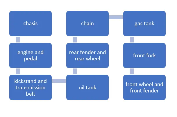
- at first assemble the chassis by giving the plane relations
- then assemble the parts by giving the mate option
- thyen check the assembly and rectify it
- then assemble the front wheel and front fender with the front fork plane relation
- then complete the assembly by checking whether there are any insection of the parts
rendering:
1. camera view( photo view 360)
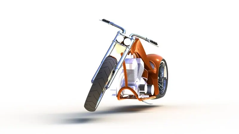
2. front view (photo view 360)
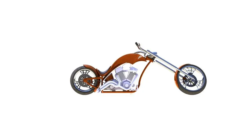
3.isometric view (photo view 360)
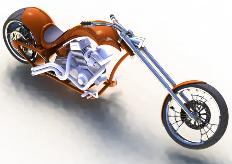
4. side view( photoview 360)
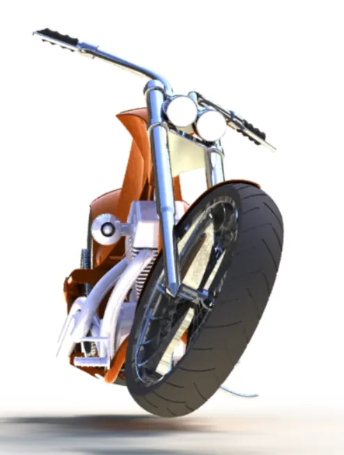
5. top view ( photo view 360)
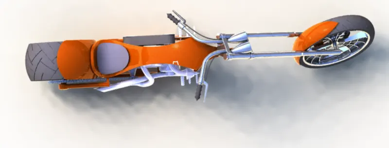
assembly link:
https://drive.google.com/file/d/1E3necG9j79s3GJIRpLqcgQ1yEaW98_5F/view?usp=sharing
gas tank link:
https://drive.google.com/file/d/1gz41Vm2otV74uK3MPs4k93EQLgg4Z-4r/view?usp=sharing