Photo Realistic Rendering
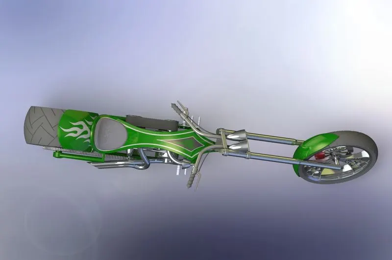
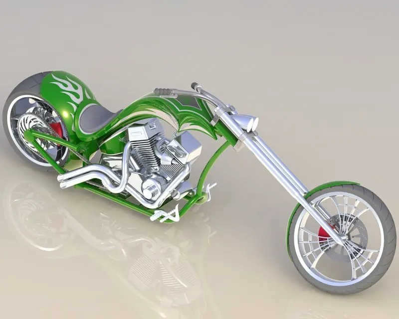
American Chopper
Title : Designing, assembling and supplying american chopper
Objective:
Create a section of American chopper files and assemble them in the same way you use using Solidworks software.
Solidworks 2021:
SOLIDWORKS 2021 enhances the capabilities and workflows you use every day for design, documentation, data management, and validation. SOLIDWORKS 2021 delivers the performance you demand so you can get your work done faster. You can also expand your capabilities and collaboration by connecting to the 3DEXPERIENCE platform. Tackle more challenges and accelerate innovation together with SOLIDWORKS 2021 and 3DEXPERIENCE WORKS.
Methodology:
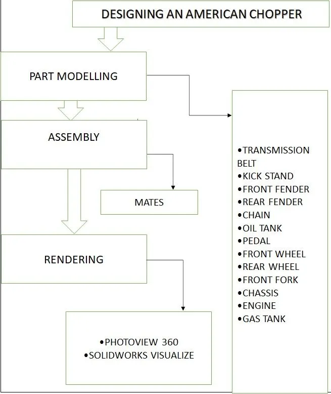
The MODELING American Chopper contains
- Belt
- Front Fender
- Chassis
- Rear Fender
- Front fork
- Fuel tank
- Oil tank
- Front wheel
- side stand
- Rear Wheel
- Engine.
The main tools / features used in solid chopper modeling activities were
1. Creating a 2D drawing:
2D drawing is the basis for creating a 3D model. It is usually created on the X-axis and on the Y-axis. This includes lines, circles, rectangles, splines, etc.
Drawing Status The current drawing status is displayed in the lower right corner of the screen.
Full Description = Black
Below Definition = Blue
Over Defined = Red
2. Geometric Relationships:
Geometric relationships are one of the most powerful elements in SOLIDWORKS.They are used at the drawing level to control the behavior of painted companies when they are moving or rotating and to keep the organizations among others.
3. Solid Extrude:
Releases a drawing or selected drawing concerts in one or two places to create a solid element .Create a drawing. You can use a closed profile drawing or an open profile. For cuts, open profile drawings are only allowed in Blind or Through All end situations .Click one extrude tool Install Boss / Base> Extrud .Click ok
4. Remove cut:
Extrude cut is a feature that helps to remove objects from a 3D model. Controls the boss / base extrude feature, because it cuts the drawing profile while extracting. It can cut in both directions and is mainly used to create holes, channels, spaces etc. Sketch on planes and / or planar areas. The drawing must be closed and defined. Then select the cut extrude command, solid cut
5.Revolve Boss:
Rotate the drawing or selected drawing rings around the axis to form a solid element. Create a new 2D drawing. Create all the solid drawing geometry on one side of the axis. Select Revolve Boss / Base from the Features menu. Select the axis you wish to use around. Specify the path and angle. Accept Feature
6.Revolve Cut:
It cuts a solid model by circling a solid profile near the axis.
7. Swept Boss:
This feature sweeps the closed profile in open or closed mode to create a solid feature. Create a line or spline diagram. Select the profile you need to remove .Choose the extrude method to perform.
8.Loft:
The loft element creates a shape by making a transition between multiple profiles and curve points thus allowing to create complex geometry with a single tool. This feature can be applied to both solid and higher models.
9.Dome:
A dome is a circular area that forms the outer surface of a body or structure, usually with a circular base. Click the Dome in the Features toolbar, or click Apply> Features> Dome. Select one or more fixed or random faces. Set the distance at which the dome grows. Click to create a concave dome
10. Curve pattern:
Curve-Based Pattern Tool lets you create patterns near a planar or 3D curve. To define a pattern, you can use any part of the drawing, or the edge of the face (solid or higher), next to the plane. You can base your pattern on an open curve, or on a closed curve, like a circle.
11. Line pattern:
Use line patterns to create multiple scenarios for one or more features that you can customize in one or two lines.
12. Circular patterns:
Use circular patterns to create multiple scenarios for one or more features that you can equally place on the axis.
13.Fillet:
Fillet / Round creates a rounded inner or outer surface on the part. You can apply all edges of the face, selected face sets, selected edges, or seam loops .Click the fillet (Feature Toolbar) or Insert> Features> Fillet. Under Fillet Parameters, select an item and set parameters .click ok
14. Chamfer:
The chamfer command is used to connect two adjacent faces using a sloping line. Click Chamfer (Feature Toolbar) or Insert> Features> Chamfer. Under Chamfer Parameters, select an item and set parameters .click ok.
15.Trim:
The cutting command is used to remove or erase additional edges of cross lines in a 2D drawing. You can use Power Trim to cut multiple businesses, close to the drawings by dragging the cursor to each drawing area.
16.Offset:
Add drawing businesses by removing faces, edges, curves, or drawing businesses in a certain range. Offset company tool is as simple as clicking geometry after starting a command
17. Split:
Use the Separate feature to create multiple sections from the existing component. You can create different parts of files, and build mergers into new sections. Click Split (Features Toolbar) or Insert> Features> Split. In Properties Manager, set options. Callout boxes appear in the photo booth up to 10 bodies at a time. Click Next 10 or Last 10 to scroll through all callout boxes for a section. Under Resulting Bodies, select the bodies you can save below, or click Automatically Assign Names. All the preserved bodies come from the photographic area and are listed in the Design Tree Properties list under Solid Bodies. The software automatically names all the bodies. You can change the names. Double-click the body name under File, type the name of the new component in the dialog box, and then click Save. The name of the new component appears in the list of resulting Bodies and in the call box. The unsaved bodies are not separated and remain with the first half. If you clear the checkbox for a separate component after saving it, that component is no longer saved as a separate business. It stays with the first part. Click OK.
18.Solid merge:
In most people, you can combine many bodies to form one body. Click Merge. (Features Toolbar) or Insert> Features> Merge. In the Properties Manager, under Application Type, select Add.
19.project curve:
You can project a sketched curve onto a model face to create a 3D curve. You can also create a 3D curve that represents the intersection of two extruded surfaces generated by creating sketches on two intersecting planes. Use selection to create a curve that represents the intersection of sketches from two intersecting planes. Create a sketch on each of two intersecting planes, closing each sketch when you are done. Align the sketch profiles such that when they are projected normal to their sketch plane; the implied surfaces will intersect, creating the required result. Under Sketch to Project, select both sketches in the flyout FeatureManager design tree or the graphics area. Select Reverse projection to reverse the direction of projection. Select Bi-directional to create a projection that extends on both sides of the sketch. Click ok.
20.Converting Entities:
You can create one or more curves in a sketch by projecting an edge, loop, face, curve, or external sketch contour, set of edges, or set of sketch curves onto the sketch plane. In an open sketch, click a model edge, loop, face, curve, external sketch contour, set of edges, or set of curves .Click Convert Entities (Sketch toolbar) or Tools > Sketch Tools > Convert Entities. In the Property Manager, click Select chain to convert all contiguous sketch entities. . Click ok.
21.Shell :
The shell tool hollows out a part, leaves open the faces you select, and creates thin-walled features on the remaining faces. If you do not select any face on the model, you can shell a solid part, creating a closed, hollow model. You can also shell a model using multiple thicknesses .Click Shell (Features toolbar) or Insert > Features > Shell. Set Thickness to set the thickness of the faces you keep. Select one or more faces in the graphics area for Faces to remove .click ok.
22.Mirror:
This allows to mirror features, faces & bodies along a face or a plane. click Mirror (Features toolbar) or Insert > Pattern/Mirror > Mirror.
23.Surface Knit:
Combines two or more adjacent, non-intersecting surfaces together. Click knit Surface on the surfaces toolbar, or click Insert > Surface > Knit. In the Property Manager, under Selections: Select faces and surfaces for Surfaces and Faces to Knit .Select Gap Control to view edge pairs that might introduce gap problems, and to view or edit the knitting tolerance or gap range. View the Knitting tolerance.
Parts:
1.Belt
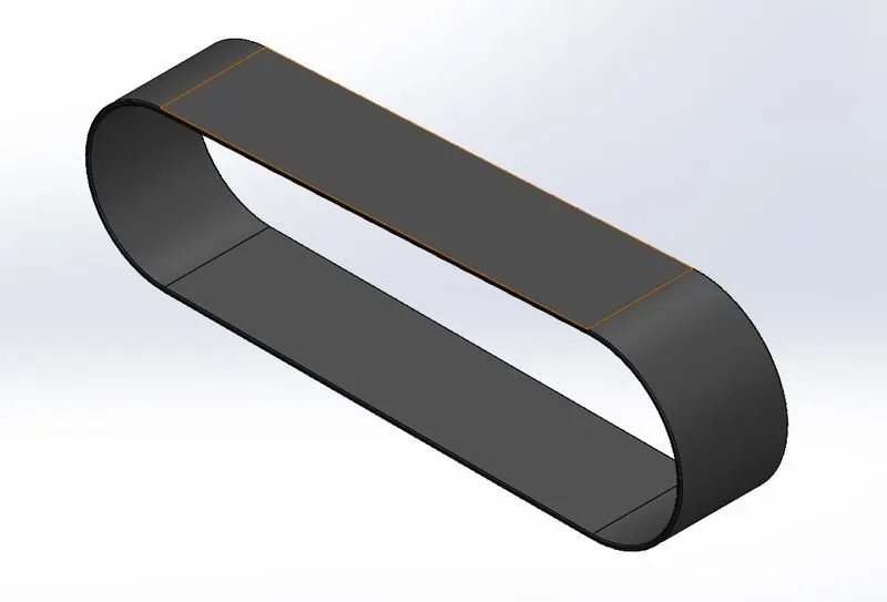
Rendered image
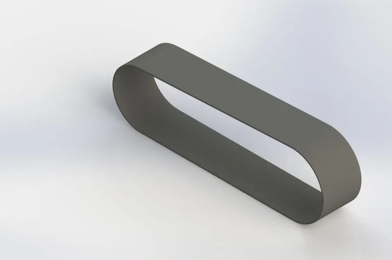
A belt is a loop of flexible material used to link two or more rotating shafts mechanically, most often parallel. Belts may be used as a source of motion, to transmit power efficiently or to track relative movement. Belts are looped over pulleys and may have a twist between the pulleys, and the shafts need not be parallel.
In a two pulley system, the belt can either drive the pulleys normally in one direction (the same if on parallel shafts), or the belt may be crossed, so that the direction of the driven shaft is reversed (the opposite direction to the driver if on parallel shafts). The belt drive can also be used to change the speed of rotation, either up or down, by using different sized pulleys.
2.Front fender
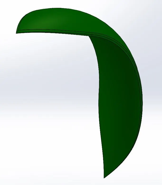
Rendered image
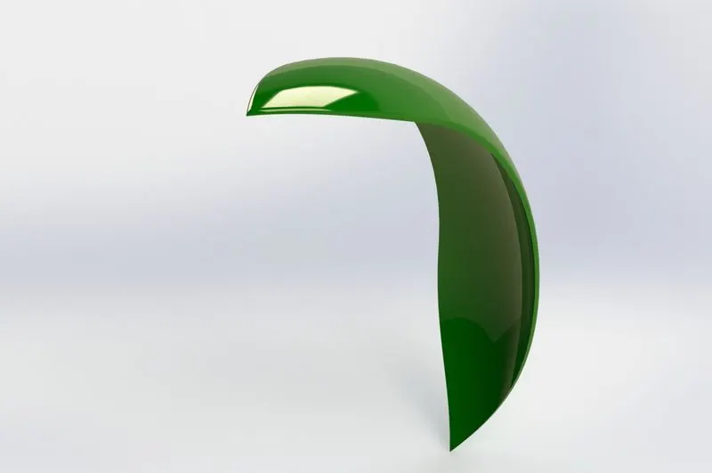
Fender is the American English term for the part of an automobile, motorcycle or other vehicle body that frames a wheel well (the fender underside).
3.Chassis
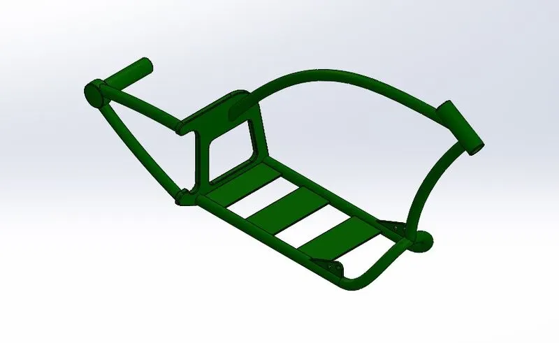
Rendered image
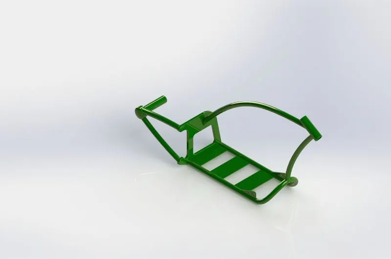
The supporting frame of a structure (such as an automobile or television) Leaf springs are attached to the car's chassis. also : the frame and working parts (as of an automobile or electronic device) exclusive of the body or housing.
4.Rear Fender
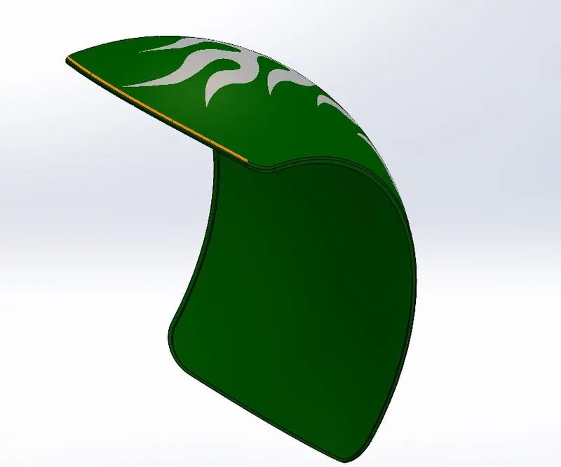
Rendered image
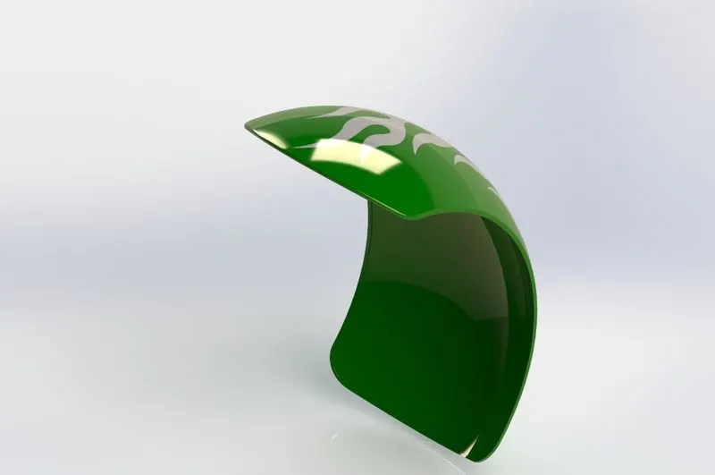
The supporting frame of a structure (such as an automobile or television) Leaf springs are attached to the car's chassis. also : the frame and working parts (as of an automobile or electronic device) exclusive of the body or housing.
5.Front fork
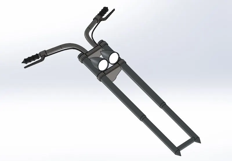
rendered image
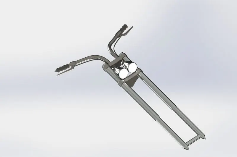
The “fork” is the suspension at the front of a motorcycle.
In nearly every motorcycle available today, the front wheel is held on by an axle that's connected to the fork. It's called a fork because it has two prongs that go around each side of the wheel.
6.Fuel tank
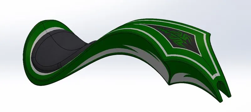
Rendered image
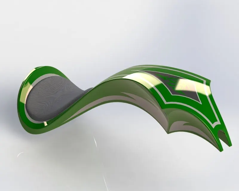
A fuel tank (also called a petrol tank or gas tank) is a safe container for flammable fluids. Though any storage tank for fuel may be so called, the term is typically applied to part of an engine system in which the fuel is stored and propelled (fuel pump) or released (pressurized gas) into an engine.
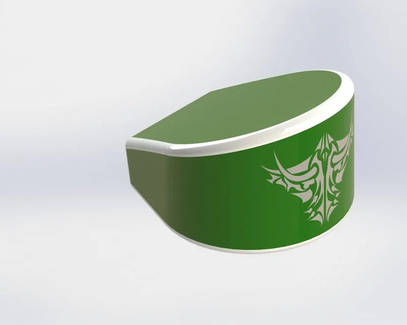
7.Oil tank

rendered image
8.Front wheel
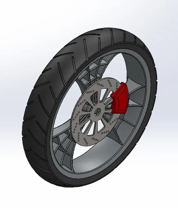
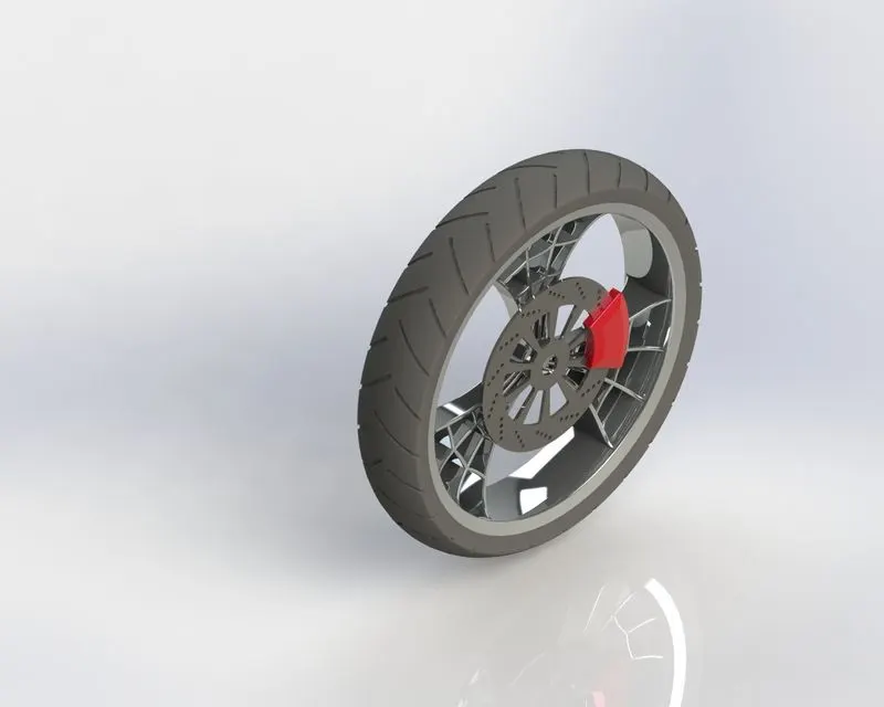
Motorcycle wheels are made to cope with radial and axial forces. They also provide a way of mounting other critical components such as the brakes, final drive and suspension
9.side stand
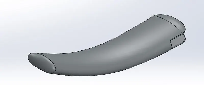
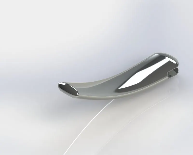
10.Rear Wheel
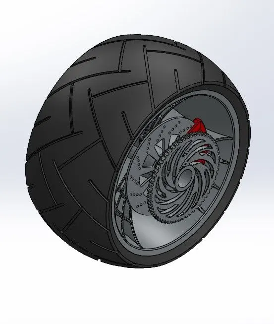
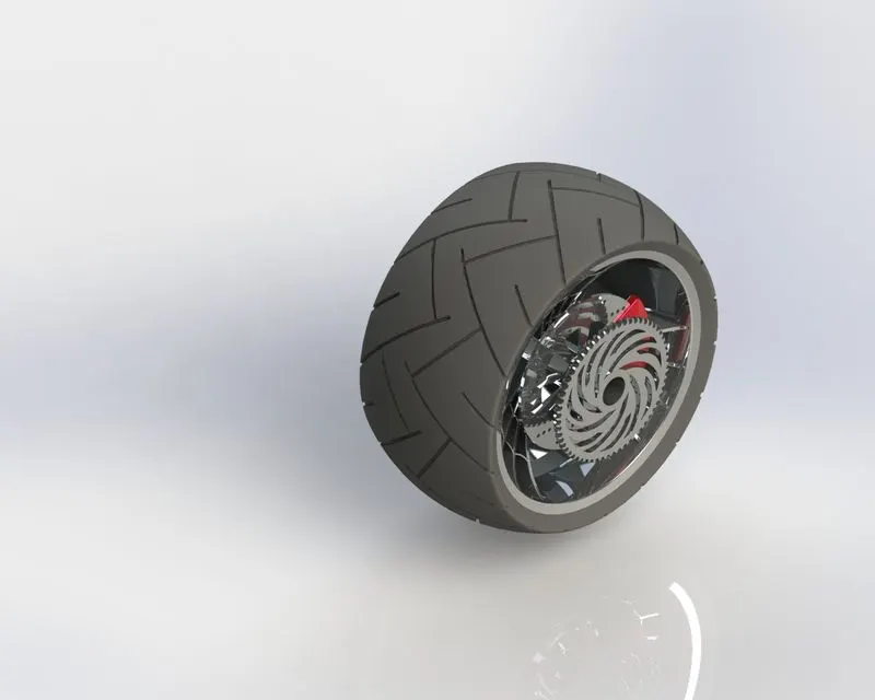
Motorcycle wheels are made to cope with radial and axial forces. They also provide a way of mounting other critical components such as the brakes, final drive and suspension
11.Engine.
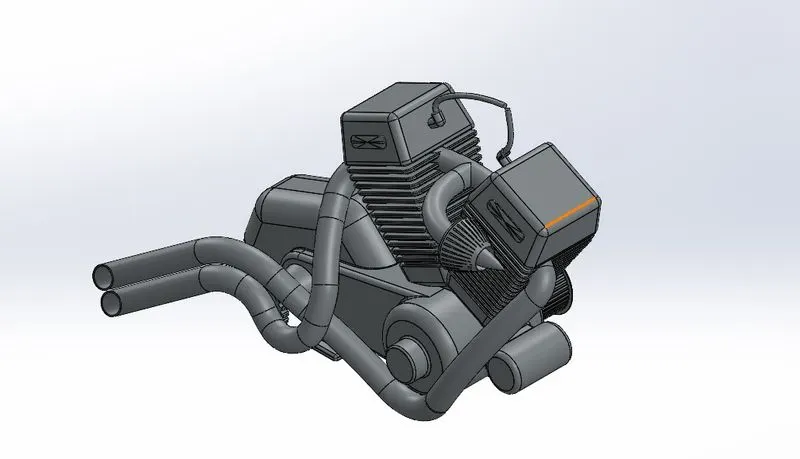
Rendered image
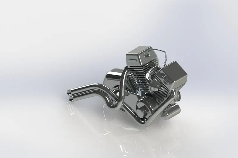
The engine is the vehicle's main source of power. The engine uses fuel and burns it to produce mechanical power. Chemical Energy converted into Mechanical Energy. The heat produced by the combustion is used to create pressure which is then used to drive a mechanical device.
Final assembled model:
We can build complex assemblies consisting of many components, which can be parts or other assemblies, called subassemblies. For most operations, the behavior of components is the same for both types. Adding a component to an assembly creates a link between the assembly and the component.
- Click Make Assembly from Part/Assembly (Standard toolbar) or File > Make Assembly from Part. An assembly opens with the Insert Component PropertyManager active.
- Click in the graphics area to add the part to the assembly. SOLIDWORKS makes the first component fixed.
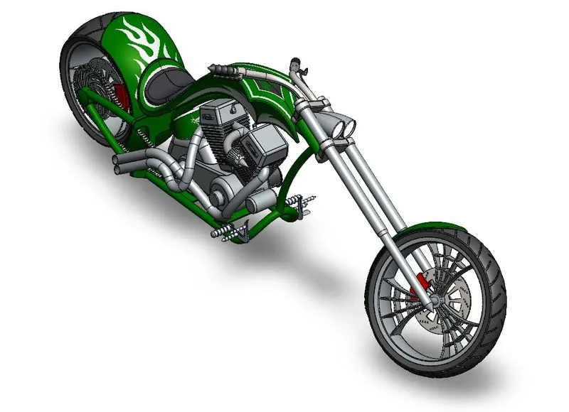
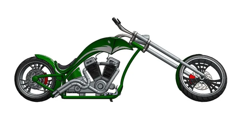
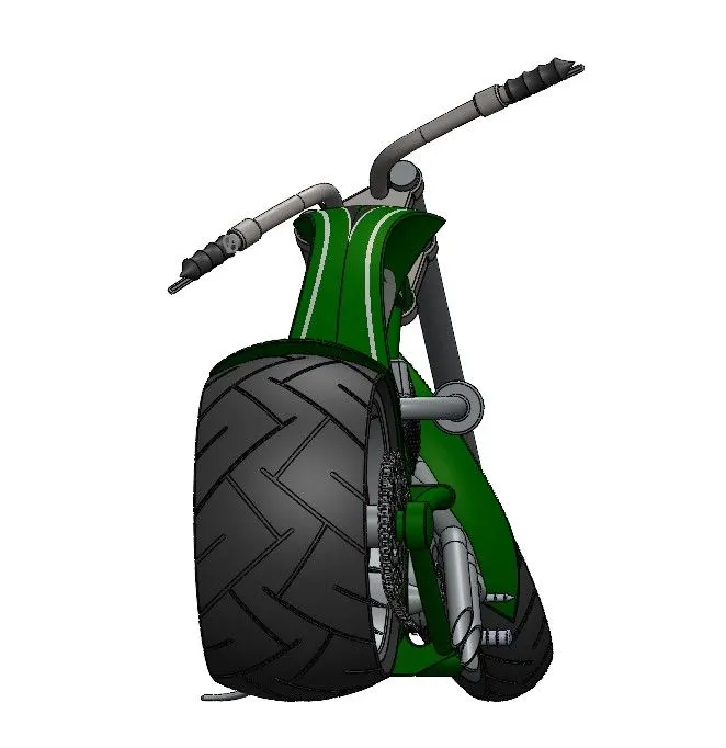
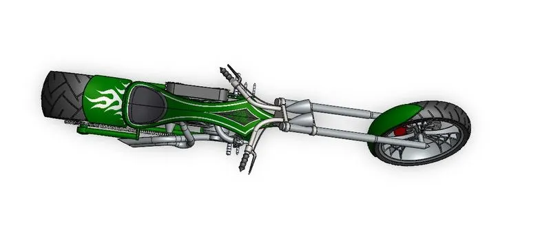
The final assembled model file attatched in Zip format with this report below.
Rendering:
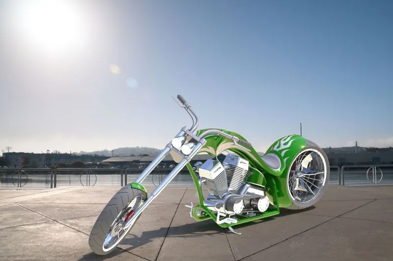
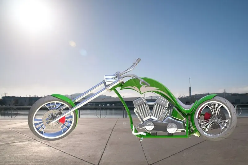
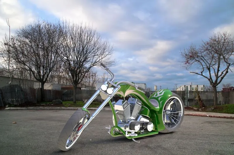
In 3-D graphic design, rendering is the process of add shading, color and lamination to a 2-D or 3-D wireframe in order to create life-like images on a screen. Rendering may be done ahead of time (pre-rendering) or it can be done in on-the-fly in real time. Rendering is the process involved in the generation of a two-dimensional or three-dimensional image from a model by means of application programs. Rendering is mostly used in architectural designs, video games, and animated movies, simulators, TV special effects and design visualization.
Conclution:
Solidworks Premium 2021 is a powerful tool that we can create any kind of 3D model then we can assembled it together to render it to get a very realistic real world view of an object.