Photo Realistic Rendering
MODELLING OF AMERICAN CHOPPER BY USING SOLIDWORKS
OBJECTIVE
To create a 3D model of the American chopper bike parts and assemble of that parts and finaly to creat photorealistic rendering image by using different tools & commends in solidworks.
INTRODUCTION
A chopper is a type of custom motorcycle which emerged in California in the late 1950s. A chopper employs radically modified steering angles and lengthened forks for a stretched-out appearance. They can be built from an original motorcycle which is modified ("chopped") or built from scratch. Some of the characteristic features of choppers are long front ends with extended forks often coupled with an increased rake angle, hardtail frames (frames without rear suspension), very tall "ape hanger" or very short "drag" handlebars, lengthened or stretched frames, and larger than stock front wheels.
DESIGN METHODOLAGY
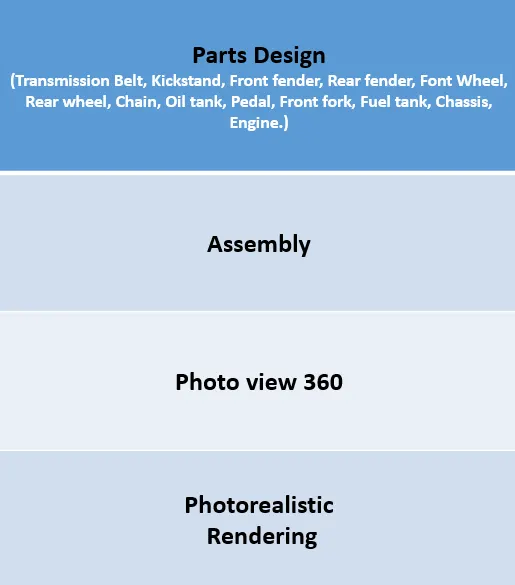
DESCRIPTION OF TOOLS
SKETCH:
The sketch is the basic for a 3D model sketch is used to draw the dimensional representation of the model with respect to the plane in solidworks. There are different sketch option availabel to create a sketch, these are known as entities.The following are entities available in the solid works-line, arc, spline, circle, rectangle, ellipse, polygon and slot .
OFFSET:
Copy a sketch entity to a specified distance from the original entity.
EXTRUDE:
Base Extrudes a sketch or selected sketch contours in one or two directions to create a solid feature.
MIRROR ENTITIES:
Create a reflected copy of a desired entity about a centerline or axis.
LINEAR SKETCH PATYTERN:
Pattern a sketch entity either horizontally, vertically, or angled. Under the property manager the user can specify the distance between the original sketch entity and the patterned copy, the number of instances, and an angle the pattern will
FILLET :
Fillet Creates a rounded internal or external face along one or more edges in solid or surface feature.
LOFTED BOSS:
Base Adds material between two or more profiles to create a solid feature.
DOME:
Dome is generally applied to give some shape to the flat faces.Select one or more planar or non planar faces
EXTRUDE CUT:
Extrude cut is another feature which helps to remove materials from the 3D modellt is just the opposite to extrudie base feature because it cuts a sketch profile while extruding.cut in both directions and mainly used for creatingholes.channels,slots
SPLIT:
In solidworks, split line tool is used to project an entity onto other surface or curved or planar face
TRIM ENTITIES:
The trim tool type is selected based on the entities want to trim or extend. All trim types are available with 2D sketches on 3D planes.
REVOLVE:
To create a revolve feature, create a sketch that contains one or more profiles and a centerline, line, or edge to use as the axis around which the feature revolve or we can turn on the temporary axis and select one of the following revolve tools.
DYNAMIC MIRROR:
Dynamic mirror is an important tool in solid works. As you sketch the entities, they are mirrored about the pre selecter sketch entity.
COMBINE:
It is used to define the thickness of thin and thick shell elements. Combine is the type of feature available in solidworks to manually combine the two bodies into a single one
SHELL:
It is used to define the thickness of thin and thick shell elements.
BLOCKS:
You can make save, edit and insert blocks for drawing items and sketch entities that you use often, such as standard notes title blocks, label positions, and so on.
PATTERNS:
The curve driven pattern tool allows you to create patterns along a planar or 3D curve pattern on an open curve on a closed curve, such as a circle. In the cahin part curve driven pattern used.
CHAMBER:
A cut on the edge or corner of something that makes it slope slightly rather than being perfectly square
LINEAR PATTERN:
It is also more like a circular pattern. The feature /bodies are patterned linearly. Pattern is a kind tool like a may available in autocad.
CIRCULAR PATTERN:
It is used to create a pattern of the sporks and the pattern available in the tyre. Also it is used to create holes in the discs of the front wheel. The parent bodies/ features are used to create a different number of instances required to create the pattern circularly.
MOVE:
It is used to move the body from one place to other place in the fork.
MIRROR:
By using mirror face with a mid plane selected only the chosen face within the revolve will be mirrored. Mirroring bodies can be used whether in a single or multi body part and allows you to select solid geometry instead of the feature and face in a body.
PROJECT CURVE:
It is the kind of 3D curve which is projected on the basis of the two different 2D sketches.
SWEEP:
With the sweep feature we can create a shape by moving a 2D sketch profile along a 2D or 3D sketch path
LOFT SURFACE:
The surface generated by multiple 3D curves or existing edges creating a smooth tangency between the selected curves.
FILLED SURFACE:
The filled surface feature constructs a surface patch with any number of side, within a boundary defined by existing model edges, sketches, or curves including composite curve.
SUFACE TRIM:
Primarily used to cut away material from a surface, and provide two modes: standard and mutual
SURFACE KNIT:
It is used to knit the two free edge / open edge of the surface together. also it reduces the gap between the two edges of the surface
SWEEP SURFACE:
The surface that are generated from a section curve positioned along a path.
PARTS TO BE MODELLED FOR AMERICAN COPPER
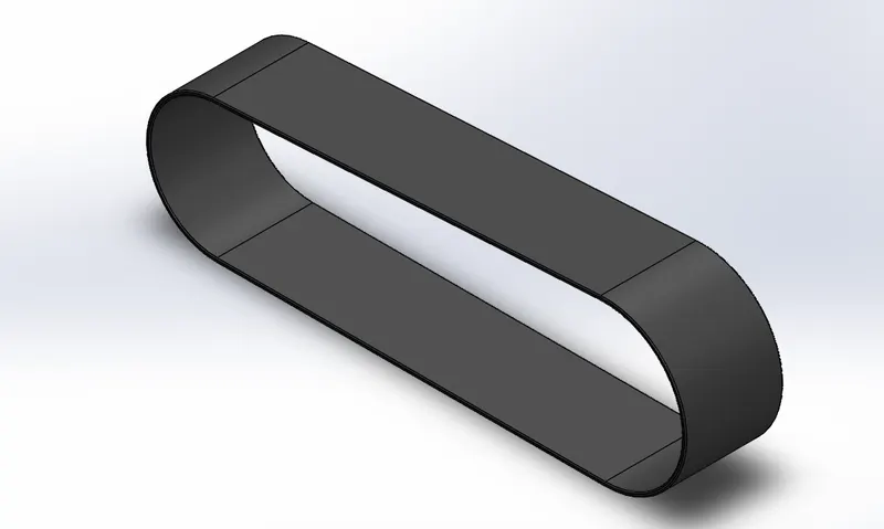
TRANSMISSION BELT:
A belt is a loop of flexible material used to link two or more rotating shafts mechanically, most often parallel. Belts may be used as a source of motion, to transmit power efficiently or to track relative movement.
Tools used to create transmission belt,
- SKETCH
- OFFSET
- EXTRUED
- FILLET
- APPEARANCES
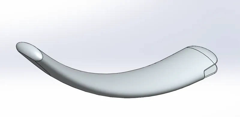
KICK STAND:
A kickstand is a device on a bicycle or motorcycle that allows the bike to be kept upright without leaning against another object or the aid of a person.
Tools used to create kick stand,
- SKETCH
- LOFT
- DOME
- EXTRUDE BASE
- EXTRUDE CUT
- FILLET
- SPLIT
- APPEARANCE
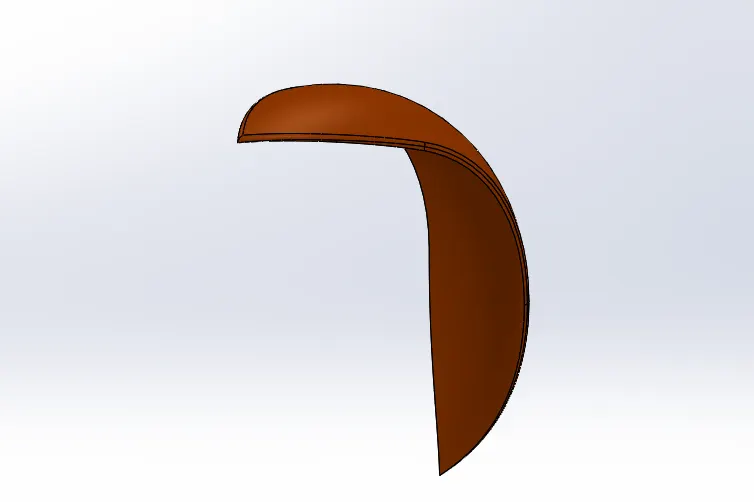
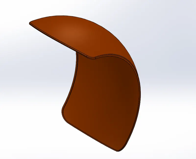
FRONT FENDER:
Fenders (or “mudguards” as people outside the U.S. call them) are what will keep you from having a skunk stripe on your backside if you ride in the rain, and a front fender will help protect your feet and ankles from spray if you're riding in the rain or even through a puddle.
Tools used to create front fender,
- SKETCH
- OFFSET
- TRIM ENTITIES
- REVOLVE
- DYNAMIC MIRROR
- SPLIT
- APPEARANCES
REAR FENDER:
Fender is the American English term for the part of an automobile, motorcycle or other vehicle body that frames a wheel well (the fender underside). Its primary purpose is to prevent sand, mud, rocks, liquids, and other road spray from being thrown into the air by the rotating tire.
Tools used to create rear fender,
- SKETCH
- Offset
- TRIM ENTITIES
- REVOLVE
- DYNAMIC MIRRO
- APPEARANCES
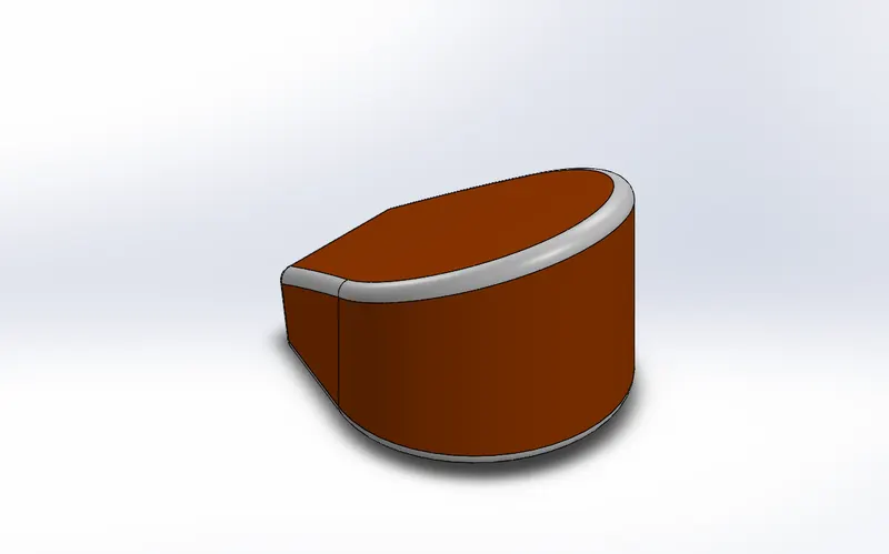
OIL TANK:
The oil tank is one of the chopper, oil tank is used to store the oil required to run the engine. Oil tank is the hollow one. The thickness of the oil tank is given as 3mm in our chopper.
Tools used to create oil tank,
- SKETCH
- COMBINE
- FILLET
- BOSS EXTRUDE
- SHELL
- APPEARANCE
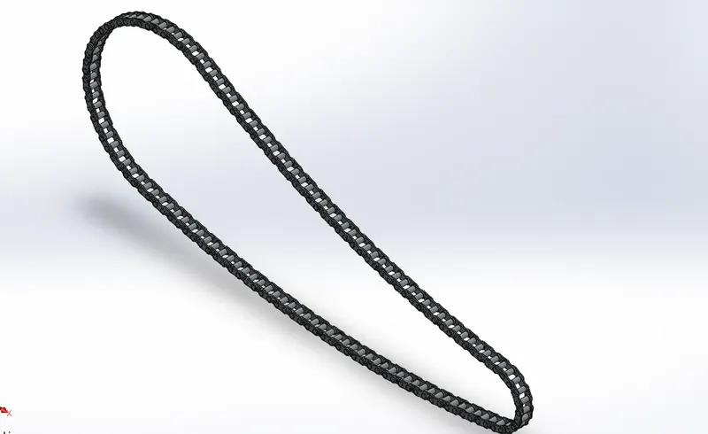
CHAIN:
Chain drive is a way of transmitting mechanical power from one place to another. It is often used to convey power to the wheels of a vehicle, particularly bicycles and motorcycles. It is also used in a wide variety of machines besides vehicles.
Roller chain and sprocketMost often, the power is conveyed by a roller chain, known as the drive chain or transmission chain, passing over a sprocket gear, with the teeth of the gear meshing with the holes in the links of the chain. The gear is turned, and this pulls the chain putting mechanical force into the system.
Tools used to create chain,
- SKETCH
- TRIM
- FILLET
- BLOCKS
- EXTRUDE
- PATTERNS
- APPEARANCE
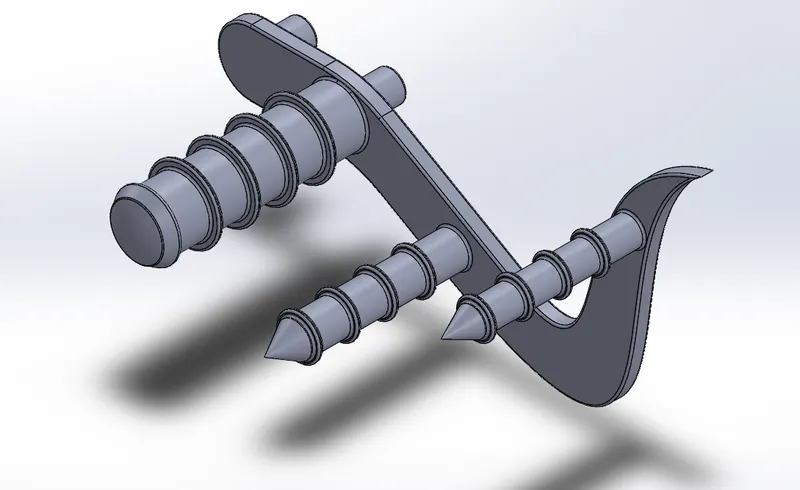
PEDAL:
It is the external part attached to the chassis. The pedal is used to place the leg on top of that. to give comfort to the rider pedal is used.
Tools used to create pedal,
- SKETCH
- EXTRUDE
- FILLET
- LINEAR PATTERN
- DOME
- CHAMBER
- APPEARANCE
WHEEL:
Motorcycle wheels are made to cope with radial and axial forces. They also provide a way of mounting other critical components such as the brakes, final drive and suspension. Wheels, and anything directly connected to them, are considered to be unsprung mass. Traditionally motorcycles used wire-spoked wheels with inner tubes and pneumatic tyres. Although cast wheels were first used on a motorcycle in 1927, it would not be until the 1970s that mainstream manufacturers would start to introduce cast wheels on their roadgoing motorcycles. Spoked wheels are usually made using steel spokes with steel or aluminium rims. Cast wheels are predominantly made from an aluminium-alloy, but can also be made from more-exotic materials, such as magnesium content alloy or carbon fibre.
They are tow wheels in bike
- Front wheel
- Rear wheel
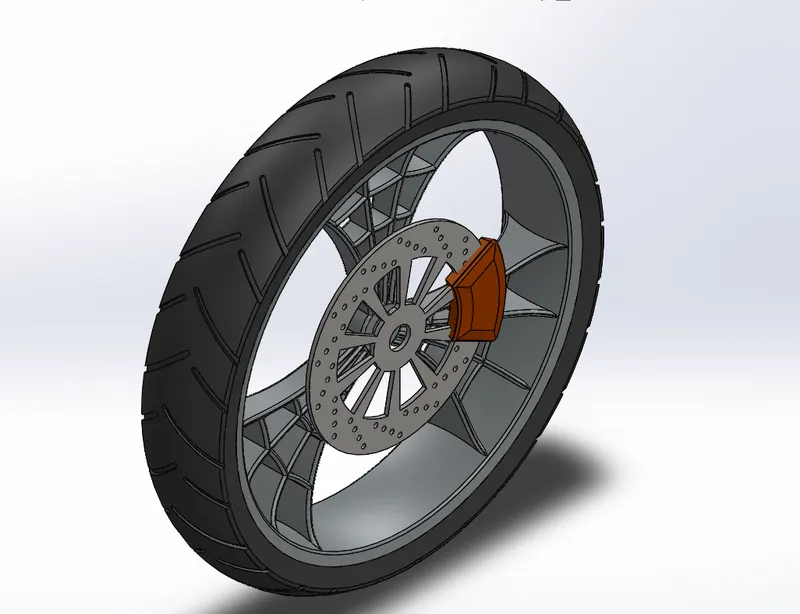
- Front wheel:
A wheel is a circular block made of the steel/ alloy material. On the top of the wheel the tyre is covered. The tyre is made of rubber and it has thin wires within it.
Tools used to create front wheel,
- SKETCH
- REVOLVE
- TRIM
- FILLET
- BAS EXTRUDE
- LINEAR PATTERN
- CHAMBER
- REVOLVE CUT
- FILLET
- CIRCULAR PATTERN
- CUT EXTRUDE
- APPEARANCE
2. Rear wheel:
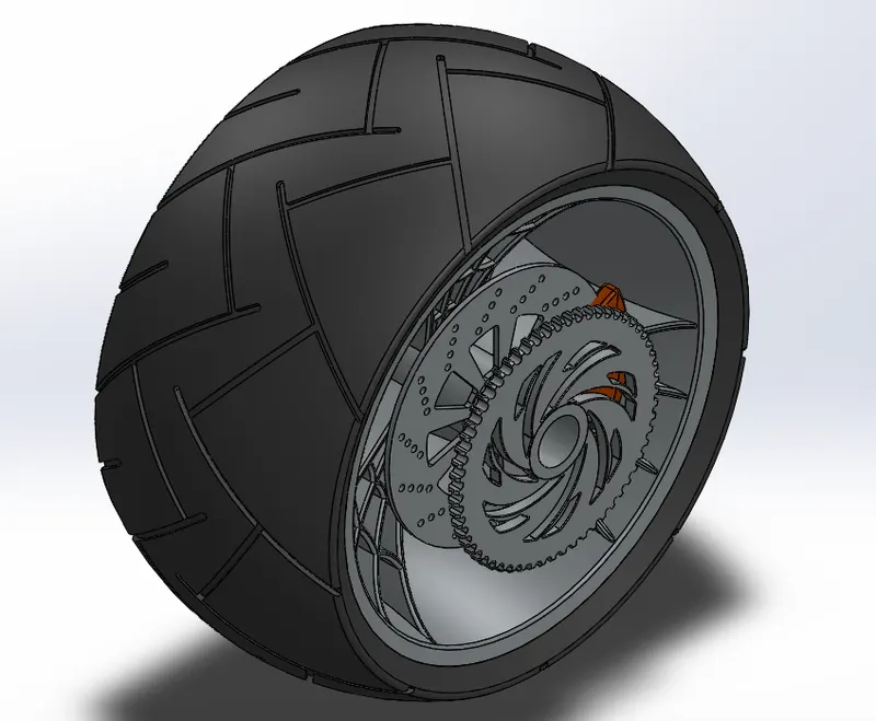
A circular object that revolves on an axle and is fixed below a vehicle or other object to enable it to move easily over the ground. The disc and sprocket are attached with a rear wheel. The chain and the rear wheel. Chain is a positive drive. Compared to the belt it will be more efficient and losses in the chain will be less comparatively.
Tools used to create rear wheel,
- SKETCH
- REVOLVE
- TRIM
- FILLET
- BASE EXTRUDE
- PLANE
- REVOLVE CUT
- LINEAR PATTERN
- CHAMBER
- FILLET FEATURE
- CUT EXRUDE
- CIRCULAR PATTERN
- APPEARANCE
FRONT FORK:
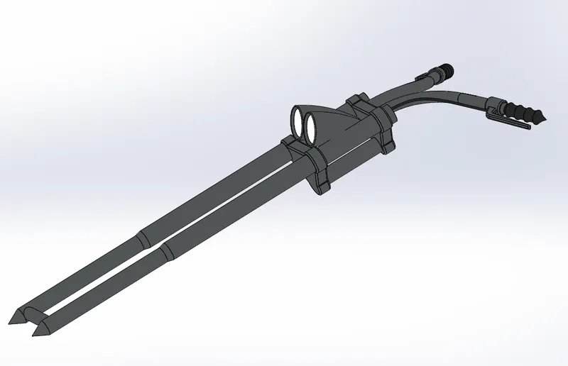
A motorcycle fork connects a motorcycle's front wheel and axle to its frame, typically via a yoke, also known as a triple clamp, which consists of an upper yoke joined to a lower yoke via a steering stem, a shaft that runs through the steering head, creating the steering axis. Most forks incorporate the front suspension and front brake, and allow the front wheel to rotate about the steering axis so that the bike may be steered. Most handlebars attach to the top clamp in various ways, while clip-on handlebars clamp to the fork tubes, either just above or just below the upper triple clamp.
Tools used to create front fork,
- SKETCH
- EXTRUDE
- TRIM
- REVOLVE
- SPLIT
- PLANE
- CONVERT ENTITIES
- MOVE
- DOME
- MIRROR
- COMBINE
- CURVE SWEEP
- APPEARANCE
CHASSIS:
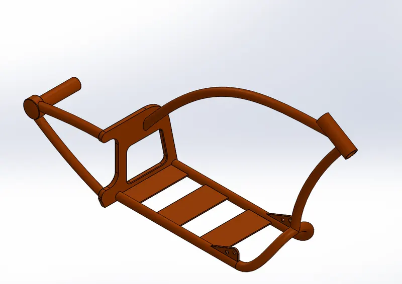
A motorcycle’s chassis or frame forms its skeleton. All the components of a motorcycle, like the suspension, wheels, fuel tank, seats, handlebars etc, are attached to this base structure which lends a motorcycle its strength and ability to handle well.
Tools used to create chassis,
- SKETCH
- CONVERT ENTITIES
- OFFSET
- PROJECT CURVE
- TRIM
- PLANE
- SWEEP
- SPLIT
- REVOLVE
- CUT EXTRUDE
- FILLET
- COMBINE
- APPEARANCE
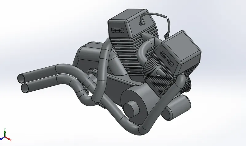
ENGINE:
A motorcycle engine is an engine that powers a motorcycle. Motorcycle engines are typically two-stroke or four-stroke internal combustion engines, but other engine types, such as Wankels and electric motors, have been used.
Tools used to create engine,
- SKETCH
- CONVERT ENTITIES
- CUT EXTRUDE
- BOSS EXTRUDE
- TRIM REVOLVE
- OFFSET
- DOME
- FILLET
- PROJECT CURVE
- COMPOSITE CURVE
- SWEEP
- MIRROR
- SPLIT
- CIRCULAR PATTERN
- APPEARANCE
FUEL TANK:
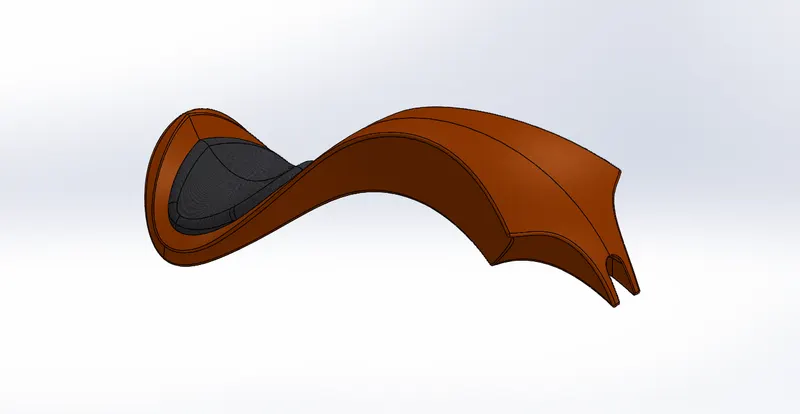
A fuel tank (also called a petrol tank or gas tank) is a safe container for flammable fluids. Though any storage tank for fuel may be so called, the term is typically applied to part of an engine system in which the fuel is stored and propelled (fuel pump) or released (pressurized gas) into an engine.
Tools used to create fuel tank,
- SKETCH
- TRIM
- CONVERT ENTITIES
- SWEEP SURFACE
- PROJECT CURVE
- FILL SURFACE
- SURFACE TRIM
- SURFACE KNIT
- SWEEP CUT
- FILLET
- APPEARANCE
ASSEMBLY OF CHOPPER
Initially, the chassis part is inserted in the assembly by using insert part in the option. After that the part is inserted in the assembly environment and clicked ok fix the chassis.After that the other parts of the chopper are inserted into the assembly and given possible mate conditions.
TOOLS USED TO ASSEMBLE CHOPPER,
- MATES
MATES
It create geometric relationships between assembly components. As we add mates, we define the allowable directions of linear or rotational motion of the components, we can move a component within its degree of freedom visualizing the assembly's behaviour.
VIEWS OF AMERICAN CHOPPER
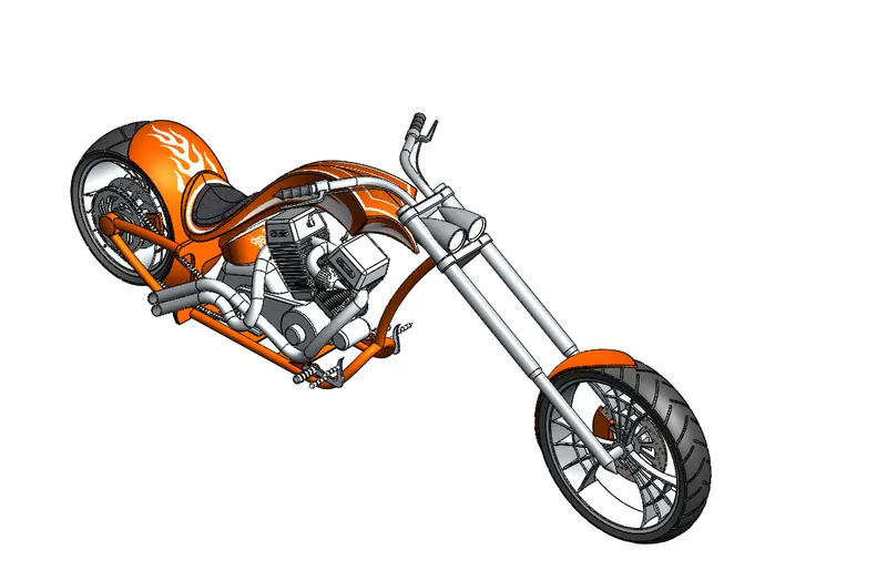
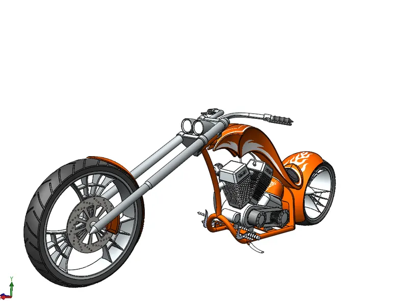
ISOMETRIC VIEW
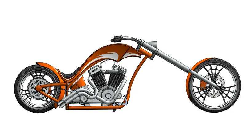
SIDE VIEW
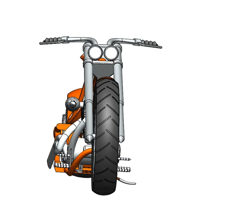
FRONT VIEW
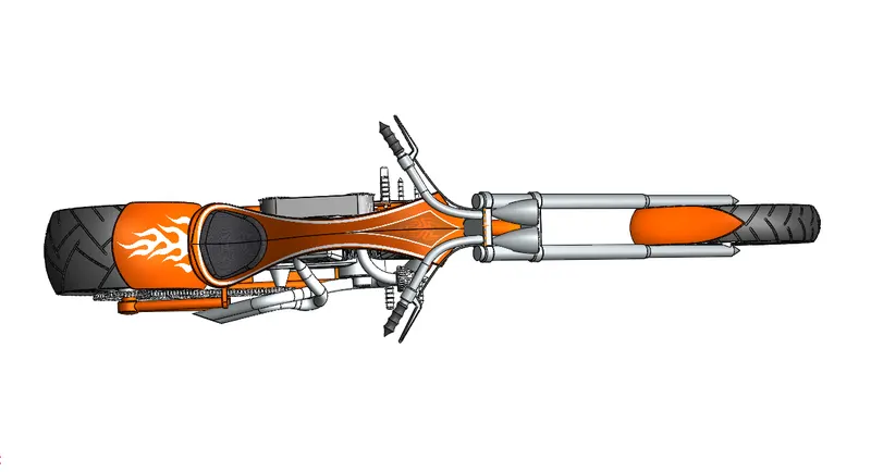
TOP VIEW
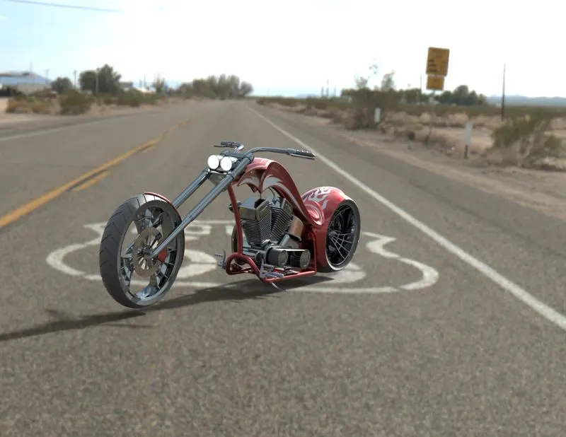
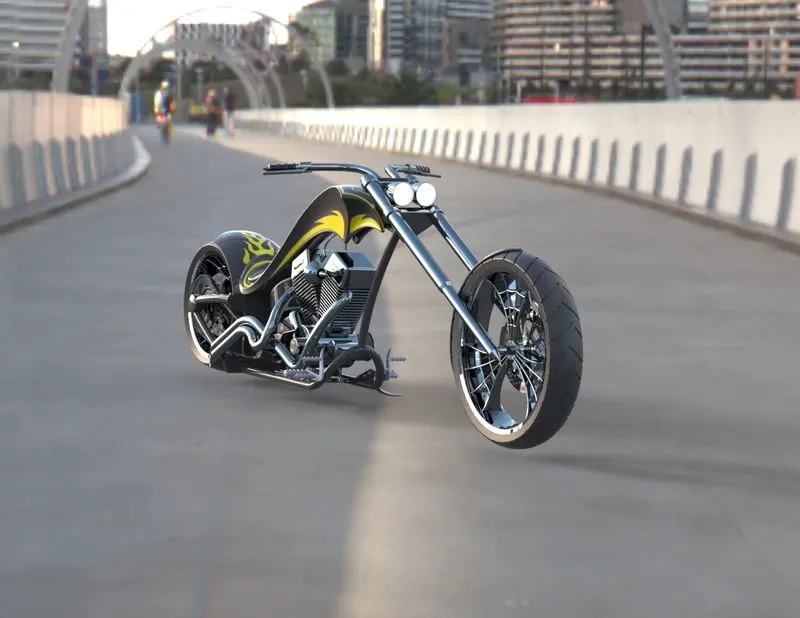
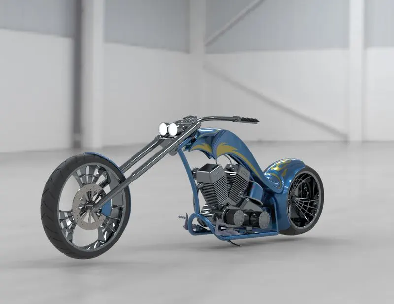
RENDERING
It is the process of creating realistic images of the photorealistic model with the environment. It has been done in two ways in solid works. The following are the two ways.
- Photo view 360
- Solid works visualize
PHOTO VIEW 360
SOLID WORKS VISUALIZE
CONCLUSION
- Learn to use many commands like Surface knit, Surface loft,Cut sweep etc...
- Assembled american chopper by understanding Concentric mate, Coincident mate, Distance mate, Angle mate and Parallel mate.
- Lern to use photorealistic model with the environment.