Radar Mast & Final Assembly of Yacht
MODELLING OF YACHT BY USING SOLIDWORKS
OBJECTIVE
To create a 3D model of the Yacht parts and assemble of that parts and finaly to create photo realistic rendering image by using different tools & commends in solidworks.
INTRODUCTION
A yacht is a larger, recreational boat or ship. The word “Yacht” comes from Dutch origin and was originally defined as a light, and fast sailing vessel used by the Dutch navy to find and capture pirates. A boat, on the other hand, is smaller in size and can be anything from a fisherman's boat to a sailboat.
DESIGN METHODOLAGY
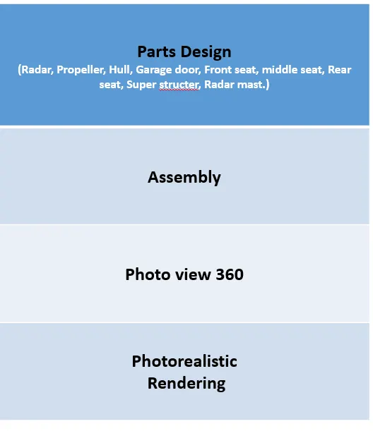
DESCRIPTION OF TOOLS
SKETCH:
The sketch is the basic for a 3D model sketch is used to draw the dimensional representation of the model with respect to the plane in solidworks. There are different sketch option availabel to create a sketch, these are known as entities.The following are entities available in the solid works-line, arc, spline, circle, rectangle, ellipse, polygon and slot .
OFFSET:
Copy a sketch entity to a specified distance from the original entity.
EXTRUDE:
Base Extrudes a sketch or selected sketch contours in one or two directions to create a solid feature.
MIRROR ENTITIES:
Create a reflected copy of a desired entity about a centerline or axis.
LINEAR SKETCH PATYTERN:
Pattern a sketch entity either horizontally, vertically, or angled. Under the property manager the user can specify the distance between the original sketch entity and the patterned copy, the number of instances, and an angle the pattern will
FILLET :
Fillet Creates a rounded internal or external face along one or more edges in solid or surface feature.
LOFTED BOSS:
Base Adds material between two or more profiles to create a solid feature.
DOME:
Dome is generally applied to give some shape to the flat faces.Select one or more planar or non planar faces
EXTRUDE CUT:
Extrude cut is another feature which helps to remove materials from the 3D modellt is just the opposite to extrudie base feature because it cuts a sketch profile while extruding.cut in both directions and mainly used for creatingholes.channels,slots
SPLIT:
In solidworks, split line tool is used to project an entity onto other surface or curved or planar face
TRIM ENTITIES:
The trim tool type is selected based on the entities want to trim or extend. All trim types are available with 2D sketches on 3D planes.
REVOLVE:
To create a revolve feature, create a sketch that contains one or more profiles and a centerline, line, or edge to use as the axis around which the feature revolve or we can turn on the temporary axis and select one of the following revolve tools.
DYNAMIC MIRROR:
Dynamic mirror is an important tool in solid works. As you sketch the entities, they are mirrored about the pre selecter sketch entity.
COMBINE:
It is used to define the thickness of thin and thick shell elements. Combine is the type of feature available in solidworks to manually combine the two bodies into a single one
SHELL:
It is used to define the thickness of thin and thick shell elements.
BLOCKS:
You can make save, edit and insert blocks for drawing items and sketch entities that you use often, such as standard notes title blocks, label positions, and so on.
PATTERNS:
The curve driven pattern tool allows you to create patterns along a planar or 3D curve pattern on an open curve on a closed curve, such as a circle. In the cahin part curve driven pattern used.
CHAMBER:
A cut on the edge or corner of something that makes it slope slightly rather than being perfectly square
LINEAR PATTERN:
It is also more like a circular pattern. The feature /bodies are patterned linearly. Pattern is a kind tool like a may available in autocad.
CIRCULAR PATTERN:
It is used to create a pattern of the sporks and the pattern available in the tyre. Also it is used to create holes in the discs of the front wheel. The parent bodies/ features are used to create a different number of instances required to create the pattern circularly.
MOVE:
It is used to move the body from one place to other place in the fork.
MIRROR:
By using mirror face with a mid plane selected only the chosen face within the revolve will be mirrored. Mirroring bodies can be used whether in a single or multi body part and allows you to select solid geometry instead of the feature and face in a body.
PROJECT CURVE:
It is the kind of 3D curve which is projected on the basis of the two different 2D sketches.
SWEEP:
With the sweep feature we can create a shape by moving a 2D sketch profile along a 2D or 3D sketch path
LOFT SURFACE:
The surface generated by multiple 3D curves or existing edges creating a smooth tangency between the selected curves.
FILLED SURFACE:
The filled surface feature constructs a surface patch with any number of side, within a boundary defined by existing model edges, sketches, or curves including composite curve.
SUFACE TRIM:
Primarily used to cut away material from a surface, and provide two modes: standard and mutual
SURFACE KNIT:
It is used to knit the two free edge / open edge of the surface together. also it reduces the gap between the two edges of the surface
SWEEP SURFACE:
The surface that are generated from a section curve positioned along a path.
OFFSET SURFACE:
The Offset Surface tool creates a new surface body from an existing set of faces. The faces may be solid or surface faces.
EXTEND SURFACE:
You can extend a surface by selecting an edge, multiple edges, or a face.
EXTRUED SURFACE:
You can create extruded surfaces from models that include 2D or 3D faces and knit the extruded surfaces to surrounding features.
DELETE SURFACE:
You can select bodies to keep or delete using the Delete/Keep Body feature. This is useful in working with multibody parts with multiple configurations.
PARTS TO BE MODELLED FOR YACHT
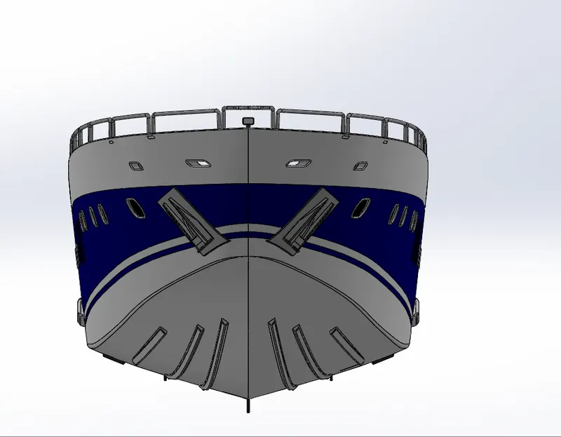
HULL:
The ‘hull’ is the portion of your boat that rides both in and on top of the water. The boat hull does not include any masts, sails, rigging, machinery or equipment.
There are three general hull types:
- PLANING HULL: This hull type is designed to glide on the surface of the water as the boat gains speed (most powerboats have this type of hull).
- PONTOON HULL: This hull type has two or more pontoons to create lift and flotation.
- DISPLACEMENT HULL: This hull type is designed to power through the water and is most often found on larger boats.
Tools used to create hull,
- SKETCH
- 3D SKETCH
- OFFSET
- EXTRUED SURFACE
- EXTEND SURFACE
- DELETE SURFACE
- FILL SURFACE
- LOFT SURFACE
- TRIM SURFACE
- SWEEP SURFACE
- FILLET
- CHAMFER
- MIRROR
- APPEARANCES
PROPELLER:
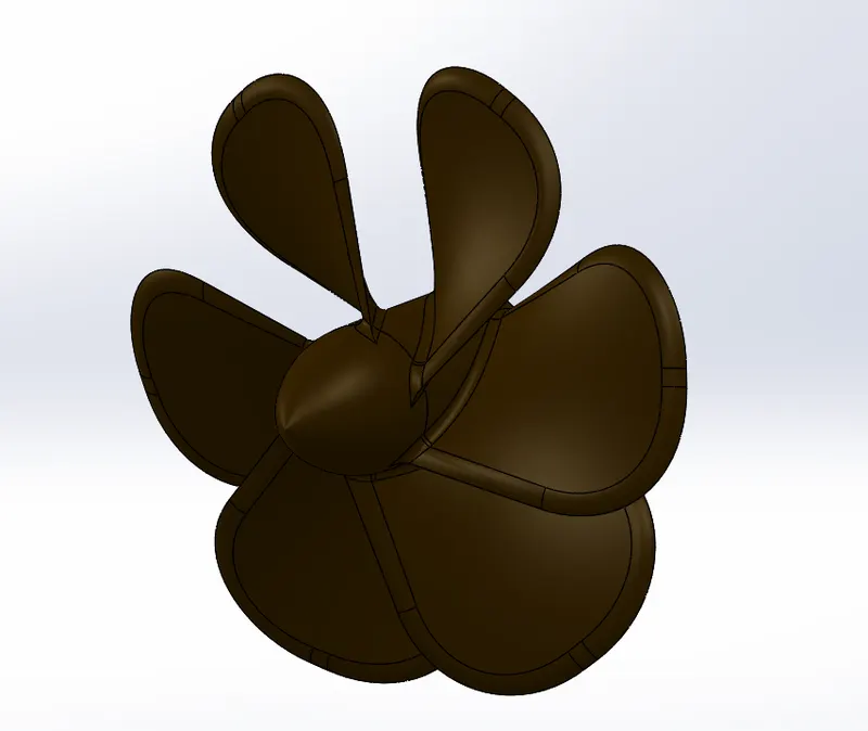
A propeller (colloquially often called a screw if on a ship or an airscrew if on an aircraft), is a device with a rotating hub and radiating blades that are set at a pitch to form a helical spiral, that, when rotated, exerts linear thrust upon a working fluid, such as water.
Tools used to create propeller,
- SKETCH
- OFFSET
- EXTRUDE
- PATTERNS
- FILLET
- CHAMFER
- APPEARANCES
RADAR:
Marine radars are X band or S band radars on ships, used to detect other ships and land obstacles, to provide bearing and distance for collision avoidance and navigation at sea. They are electronic navigation instruments that use a rotating antenna to sweep a narrow beam of microwaves around the water surface surrounding the ship to the horizon, detecting targets by microwaves reflected from them, generating a picture of the ship's surroundings on a display screen.
Tools used to create radar,
- SKETCH
- OFFSET
- EXTRUDE
- PATTERNS
- FILLET
- CHAMFER
- APPEARANCES
RADAR MAST:
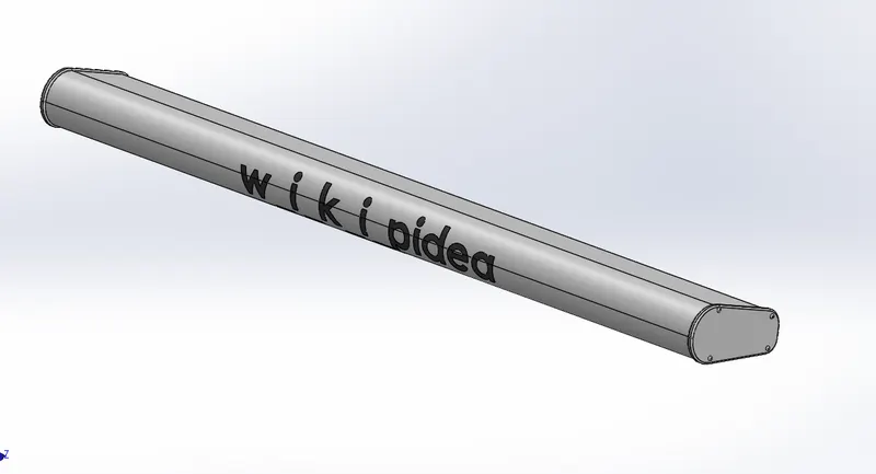
The definition of a mast is a tall pole used for support of the sails on a boat. An example of a mast is the pole that holds up the sails and radar on a ship.
Tools used to create radar mast,
- SKETCH
- OFFSET
- EXTRUDE
- PATTERNS
- LOFT
- SWEEP
- FILLET
- CHAMFER
- APPEARANCES
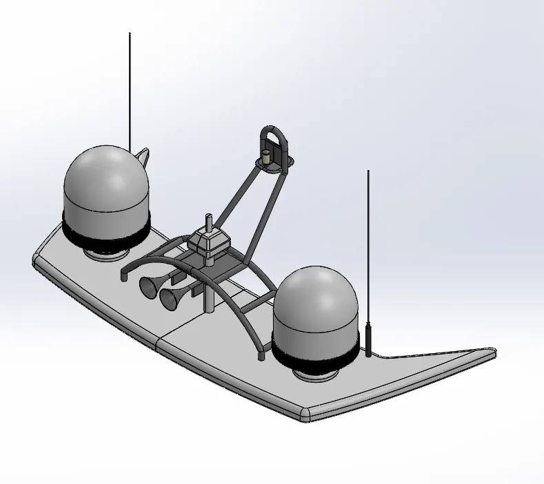
GARAGE
A garage door is a large door on a garage that opens either manually or by an electric motor. Garage doors are frequently large enough to accommodate automobiles and other vehicles. Small garage doors may be made in a single panel that tilts up and back across the garage ceiling.
Tools used to create garage door,
- SKETCH
- OFFSET
- EXTRUDE
- CUT EXTRUDE
- PATTERNS
- FILLET
- CHAMFER
- APPEARANCES
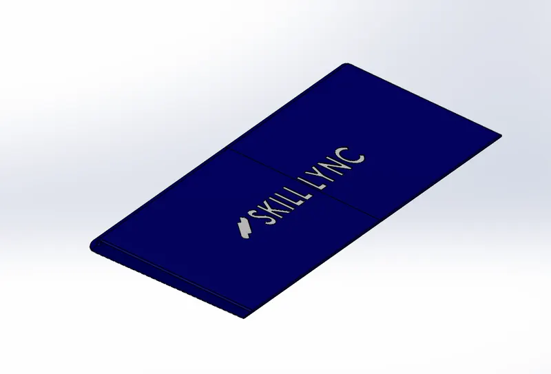
SUPERSTRUCTURE
The definition of a superstructure is a building or part of a building built above the foundation. An example of a superstructure is the lobby and floors in a high rise building. A structure built on top of another. That part of a ship above the main deck.
Tools used to create superstructure,
- SKETCH
- 3D SKETCH
- OFFSET
- EXTRUED SURFACE
- EXTEND SURFACE
- DELETE SURFACE
- FILL SURFACE
- LOFT SURFACE
- TRIM SURFACE
- SWEEP SURFACE
- FILLET
- CHAMFER
- MIRROR
- APPEARANCES
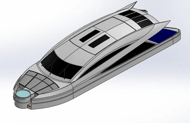
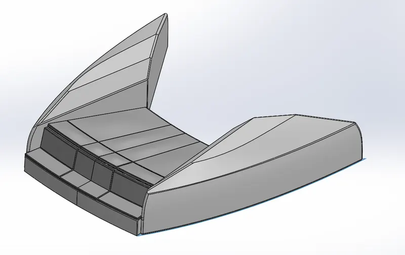
SEATS:
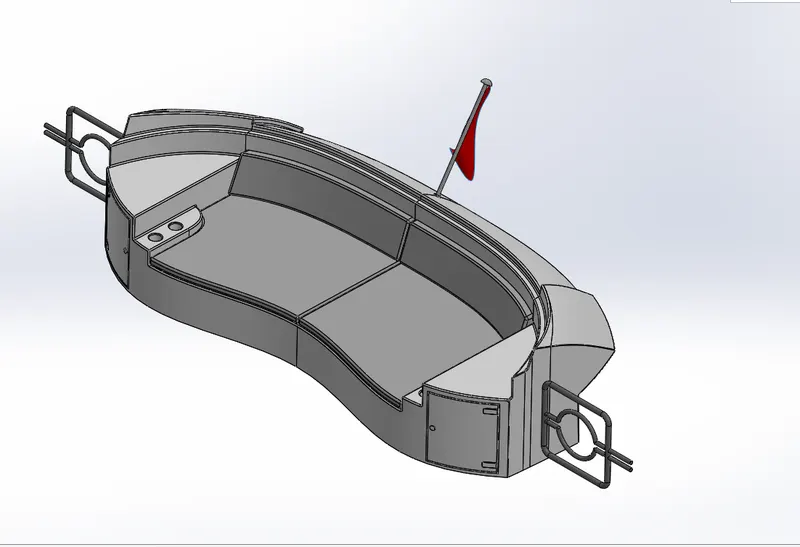
They are three seats are create in this model,given below
Tools used to create,
- SKETCH
- 3D SKETCH
- OFFSET
- EXTRUED SURFACE
- EXTEND SURFACE
- DELETE SURFACE
- FILL SURFACE
- LOFT SURFACE
- TRIM SURFACE
- SWEEP SURFACE
- FILLET
- CHAMFER
- MIRROR
- APPEARANCES
- REAR SEAT:
- MIDDLE SEATS
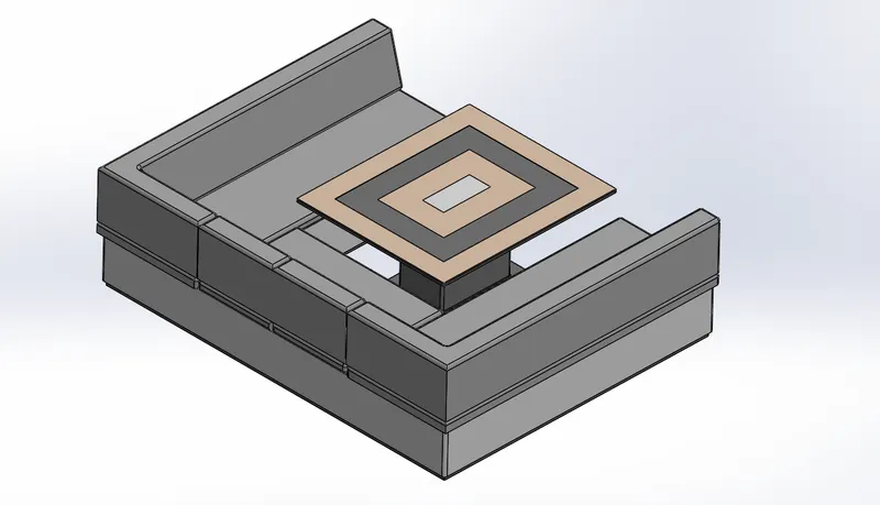
- FRONT SEATS
ASSEMBLY OF YACHT
Initially, the HULL part is inserted in the assembly by using insert part in the option. After that the part is inserted in the assembly environment and clicked ok fix the hull.After that the other parts of the yacht are inserted into the assembly and given possible mate conditions.
TOOLS USED TO ASSEMBLE YACHT
- MATES
MATES
It create geometric relationships between assembly components. As we add mates, we define the allowable directions of linear or rotational motion of the components, we can move a component within its degree of freedom visualizing the assembly's behaviour.
RENDERING
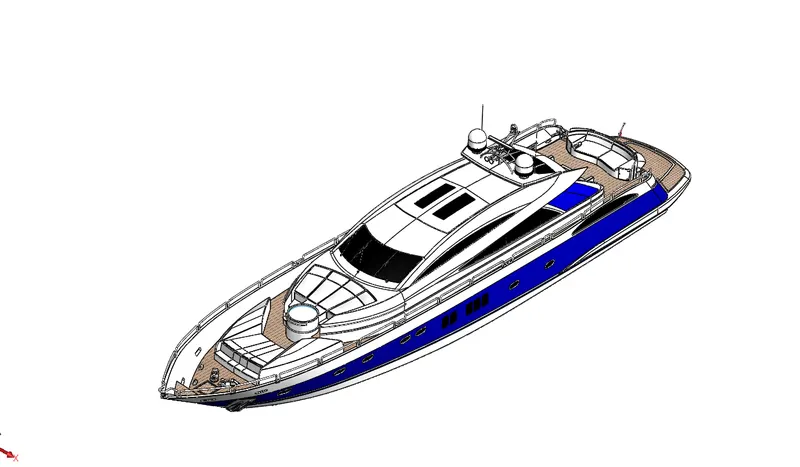
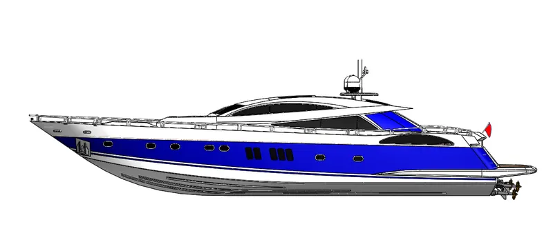
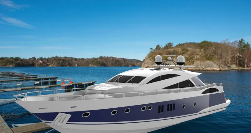
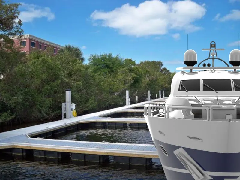
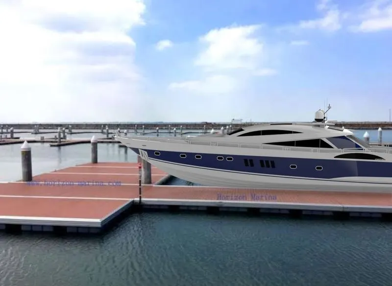
It is the process of creating realistic images of the photorealistic model with the environment. It has been done in two ways in solid works. The following are the two ways.
- Photo view 360
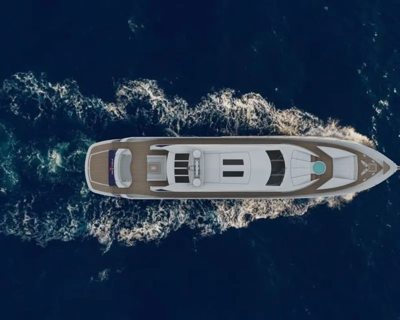
- Solid works visualize
PHOTO VIEW 360:
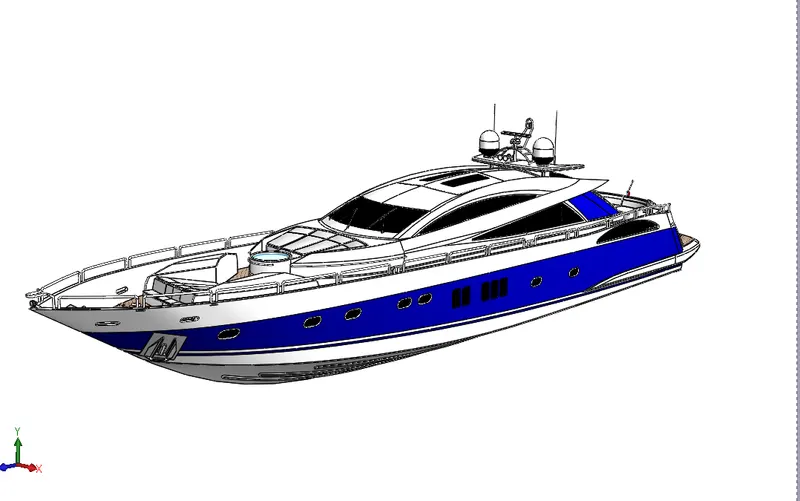
Isometric view
SIDE VIEW
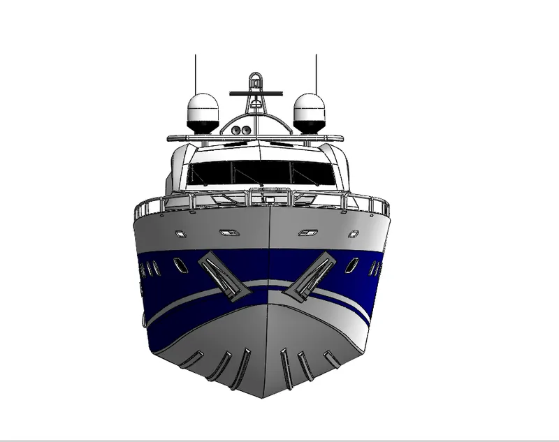
FRONT VIEW
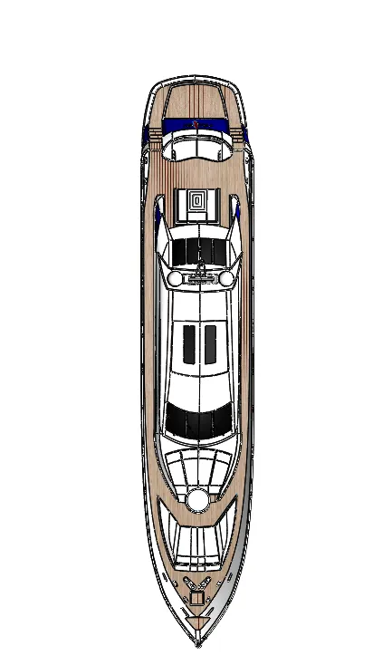
TOP VIEW
CAMERA VIEW:
SOLID WORKS VISUALIZE:

CONCLUSION
- Learn to use many commands like Surface knit, Surface loft,Cut sweep etc...
- Assembled Yacht by understanding Concentric mate, Coincident mate, Distance mate, Angle mate and Parallel mate.